In this post I have explained a small induction heater circuit for school project and exhibitions, using a very ordinary IC 555 astable PWM circuit. The idea was requested by Mr. Anthony
Technical Specifications
For a school project i need to construct an AC induction cooktop and was wondering if you could help me put together a part list for a much weaker induction cooktop than yours, it only has to warm up a few ML's of water.
Is this something that is possible?
The Design
An induction heater is considered as an amazing circuit which is capable of converting electricity into heat with utmost efficiency and without much losses.
However a little contemplation will make you realize that actually it's just the opposite. An induction heater circuit is an extremely inefficient circuit which converts all the electricity into heat.
This opinion is with regards to the general view about electrical and electronic circuits where the emission of heat is considered to be inefficient and undesirable.
But for an induction heater, this inefficiency attribute becomes its positive aspect, and the more inefficiently it is designed, the more beneficial it becomes for the user.
To be precise, an induction heater is an inefficient transformer which is purposely mismatched with its frequency and the core material specifications.
In this concept the core is normally a ferromagnetic material such as iron having a copper coil wound over it. The copper winding around this iron core is oscillated at a relatively higher frequency which may be not suited for the iron material.
The bad conductor nature of iron finds it difficult to resonate at the high winding frequency resulting in the generation of high back emf eddy currents which in turn causes high temperatures on the core material.
This feature is exploited in induction heaters for the intended purpose of achieving high temperatures
Although massive induction heater units can be built for generating extremely high temperatures using the same concept, a small induction heater circuit for school exhibition project can also be implemented easily using ordinary parts such as a IC 555 and some other inexpensive passive components.
Circuit Diagram
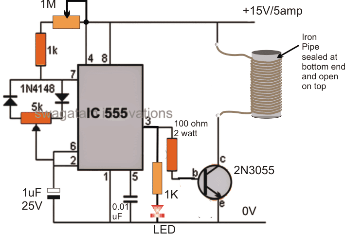
Circuit Operation
A simple IC 555 induction heater circuit for school project is shown in the above figure.
Here the IC is configured as a PWM generator circuit, which is adjusted using the 5 K pot. The frequency is adjusted by tweaking the 1M pot or the 1uF capacitor specifically for achieving the optimized heating effect on the work coil.
The working coil here is made by winding around 50 turns (not critical) of 1mm super enameled copper wire over a fabricated iron pipe whose dimensions may be selected as per individual preference, and could be anywhere between 10 to 20 mm in diameter and 30 to 40 mm long.
Once the above set up is built and switched ON, the coil and the iron pipe could be seen developing heat gradually, and anything placed inside the pipe could be witnessed getting heated up.
If it's water inside the pipe, then it could begin warming up and even reach the boiling point if the coil is optimized correctly through the frequency and PWM adjustments.
The idea behind this small induction heater circuit is simple, it is to force the iron pipe atoms to electromagnetically oscillate at an incompatible frequency resulting in the production of huge amounts of opposing eddy currents and a proportionate amount of heat due to this opposing current in the metal.
If you have more questions regarding this induction heater circuit for school science project, do feel free to ask them through comments, below.


Questions & Answers
Hi Swagatam Majumdar,
Thank you for explaining this concept in such an understandable way. I would like to know if I want to change the pipe diameter and the length of the pipe were the working coil turns lets say an old 55galon oil drum with dimensions of 580 diameter and length of 900mm, which components do I need to change to accommodate this change. I will be using the same thickness wire?
Thank you
James Posthumus
Thank you James, Yes it is possible to use the concept with any desired coil set up.
You just have to optimize by matching the frequency with the inductance to get most efficient results from the design.
you can use the following software for the adjustments
https://www.homemade-circuits.com/p/resonant-frequency-calculator.html
Dear Swagatan,
Is the circuit work with coil winding 100-120mm?
Thanks for your attention,
Regard,
Dear Fery, yes it should work, but you will have to adjust the frequency correctly since it is not a ZVS circuit…
Sir,
I want to build a induction cooktop which can work on 400 watt power, please tell me how to design circuit for it
Deepak, buy a readymade induction heater kit or PCB module. Remove its main work coil, measure its inductance, make another work coil which will be flat as per the cook top specifications, connect it with the circuit. Test the response!
the components will not require any changes for your requirement
Sir
Power supply is from solar panel, inverter and battery setup which produce 550 watt power.
When I connect induction cooker, inverter goes trip, can we do some change in circuit of induction to overcome the problem of inverter trip
Deepak, please provide all the details regarding the solar panel and the induction heater, so that I can understand the operations correctly.
hi swagatam sir ,i need 8 channel LED GLOW Circuit which Voltage/ Amp transformer using and how much LED series need
Hi Swagatam,
Thank you I will play with this concept a bit and do some calculations. I'm new to this inductive heating stuff and I hope I will get the figures right.
James.
Hi Swagatam,
I would like to temperature control this coil, can I insert the relay contacts of a temperature controller between the 100ohm 2watt resistor and the base of the transistor to do the controlling?
Thanks
James
Hi James, it is possible, a better option would be to insert the contacts between base of the transistor and the ground of the circuit….so whenever the relay trips it grounds the base……
Hi Swagatam,
Thank you, will I be able to reach temperatures of 420 degrees Celsius with this circuit?
Thanks
James
Yes you can, by replacing the BJT with an IGBT and by using calculated thick wires for the coil and also by using high amps with the supply input
Hi Swagatam,
So I will need to increase the amps, but my input voltage will stay at 15v?
Thanks
James
Hi James, the input voltage can be 15V, amps will need to be increased until the desired temp range is satisfied
Hi Swagatam,
Which IGBT can I use? I have a 230VAC TO 16-18VAC transformer, which state 50VA on the information plate, I'm not sure when you say high amps input, how high are we talking about?
Thanks
James
Hi James, You can try a mosfet also, a IRF540 will work……50VA will just produce 3 amp current hardly enough to make the drum hot….you will need at least 15 to 20 amp current to achieve temperature near 400 degrees.
Hi Swagatam,
I sat with your information and used your calculators and this is what I got-
If we work with that wire thickness rule-of-thumb table and the amps that you suggest that will be used, then I see copper wire thickness of 2,5mm with a length of 92m or 307 feet with 50 turns. The frequency will be 2600Hz using a 1 microfarad. Is this figures correct?
Thank you
James.
Hi James, you will first need to wind the coil on the core, measure its inductance and then use the suggested calculator to find the resonance frequency for it….for practical verification you would need to oscillate the coil at the calculated frequency using any standard oscillator and transistor driver.
the wire gauge can be later on determined with trial and error
sorry, I design circuits only for my site, I don't accept fees for it.
there are already many readymade induction heater circuits in this website you can refer to this link for more info
https://www.homemade-circuits.com/search/label/Induction%20Heater
hi Mr. Swagatam can i have a simple 555IC project assembled in breadboard..this is my first breadboard project so it will be a big help for me if you do help. tnx More power
Hi Renz, you can search online for "IC 555 LED flasher circuit" you will be able to find plenty of options which you can try
The current running in the coil is always 15mA however i increase the current so no heat is generated .. Any help?!
Hello again Mr. Swagatam!
Thank you for your quick response.
We are able to adjust the distance between the two containers so that we can get down to a distance of about 2 mm between the coil and the bottom of the inner container.
Hi Suni,
70mm contact surface looks too small to force quick boiling of water inside, especially if it's 2mm away from the flat induction coil….would it be possible to insert the container through the coil? In this case we can have use cylindrical coil instead of flat spiral type so that the container can be inserted through the coil for enabling an effective induction from all the sides
It is possible to insert the container through the cylindrical coil but it is best from the botton due to the construction. Is there a difference in the design of the circuit either if we use a coil at the bottom or as a cylinder?
If not then we can see if the time to reach the boiling point is acceptable either way.
OK, I will try to design it, in the meantime you can read the following article which comprehensively explains how to design a specific induction heater circuit from the scratch
https://www.homemade-circuits.com/2016/09/designing-induction-heater-circuit.html
Thanks for this usefull information.
We are looking foreward to create the circuit.
Just to prepare ourselwes – can this circuit that you are about to design be used both with a cylindrical coil and a flat bifilar coil?
Regards
Súni
yes, the coil shape and structure is not relevant with the circuit… you can dimension it as you want…the inductance value and the resonance are the only factors which become crucial for getting the results.
Hi Mr. Swagatam!
I refer to the insulated container and induction coil which we have corresponded about. Is it possible to get an infrared temperature measurer or infrared thermostat that can measure the temperature of the water through the stainless steel wall of the container. Does such a thing exist? It is for the porpose to hold the water at a constant temperature.
Regards
Súni Christiansen
Hi Suni, you can try a "thermopile sensor circuit" for achieving an infra-red temperature sensing and control
Hi again Mr. Swagatam!
How does one of these look like – have you got a simple circuit of it?
I am asking the question abowe, because the construction of the insulating containers prevents the possibility to mount an ordinary thermostat to the wall of the inner container. Also in periods there is water in the space between the containers.
Regards
Súni
Hi Suni, Here's one example design that you can try,the sensor points may be compatible with other variants too having similar technical specs
/blog/2017/01/simple-infrared-thermopile-sensor-circuit-explained.html
Thanks!
The circuit diagram says 9 V input. How can I use this in connection with the 0-25 V induction circuit?
Regards
Súni
You can use a 7809 IC in between the 25V and the IR circuit Vcc…..
Dear Mr. Swagatam!
I've been away for a while and have not seen if you have published a diagram of the induction circuit.
I plan to use the diagram in a school project that starts in the first half of February. Have you had time to design it and is the diagram available at your site.
Best regards
Súni Christiansen
Dear Suni,
you can find the published article in the following link
https://www.homemade-circuits.com/2017/01/induction-heater-circuit-for-labs-and.html
Dear Mr. Swagatam!
Thank you very much for your kindness to publish this usefull information. I will keep you updated as we construct the circuit.
I have some clarifying questions as to be on the safe side and avoid to blow it all up:
1. We have a Max Current at 15 Amp. Therefore we get Rx=0,0466 Ohm. Is this right?
2. We have selected the frequency at 50 kHz. According the frequency vs. RT graph in the datasheet for the IRS2453 we get CT=470pF and RT=30 Ohm. If we put these values in the equation F=1/1,453 x RT x CT we get F=48.810 Hz which is very close to 50 kHz. Is this right?
3. We have a problem finding the values for L and C. Do we have to make the coil first and then measure the inductance (in Henry) for thereafter to catculate C by solving the equation F=1/2 x PI x root(L x C)?
4. As you mentioned in the article the IC is equiped with a shutdown (SD) funktion. We plan to connect a tilt switch that will cut the power off if the container is tilted. Do you recommend to connect the tilt switch to the SD-pin and in connection with the BC547 and Rx?
I probably will get back to you later conserning the thermophile sersor circuit and where and how to connect it. First we aim at getting the induction circuit to work.
Thank you verry much and hawe a pleasent weekend!
Yours sinserely
Súni Christiansen
Dear Suni,
the best way to fix the frequency is by practically testing the result through a frequency meter.
you can use the mentioned value for the Rt/Ct and confirm the output using a frequency meter.
for L and C setting, you can first make the L as per the load dimension, wrap it around the load and measure its inductance.
Once you know the value of L and the frequency, you can easily calculate the value of C with the help of the recommended software.
you can use a tilt switch with the shut down pin, but make sure the current control transistor is also included with this pinout.
Dear Mr. Swagatam!
What type and thickness of wire would you recommend for the spiral?
Regards
Súni
how can i bild 50w induction cooktop with 50w halogen transformer circuit
Hi Swag, thanks alot for the fascinating post.
What is the coil gauge used for winding and how many turn is it?
Thanks Oyenkule, please seetthe fifth paragraph from the bottom of the article, you will be able to find the required coil data there…
Yeah yeah i find it. Thanks
Hi….Mr swagatam, pls I intend to use 230v mains as my input voltage instead of 15v …..what changes do I need to make in your circuit diagram?
Hi Daniel, you can use a 0-12V/10amp transformer to step down the 220V mains to 12V and then rectify, filter it using 4 diodes and a filter capacitor rated at 6800uF/35V.
This will raise the voltage to over 15V just suitable for the project.
correction: 10 amp transformer is not required, 3 amp will be more than enough
I made one using 555 timer. Here is it in action. I can provide a circuit if you are interested.
You can send it to my email: homemadecircuits @ gmail.com, I’ll post post here
Wonderful circuit and I intend to construct one. Please clarify the questions below:
a) Can I use 12 Vdc instead of 15 Vdc. My intention is to use solar energy storage in a battery;
b) Can we control the temperature adjusting 1M pot?
The purpose of my application is to smelt welding scraps.
Thanks for appreciating my circuit. here are the answers:
a) yes 12V can be used instead of 15V
b) 1M adjustment is fundamentally used at the start for setting the best frequency, which will allow achieving maximum heat, the 5K pot can be actually used during practical operation for controlling the heat on the coil.
smelting scrap might require a huge amount of current, with a well calculated coil and mosfet arrangement in the circuit.
Thanks for prompt reply!
So you recommend Mosfet instead of NPN transistor?
yes, a mosfet is normally recommended if the current requirement is on the higher side…
Can i use astable multibrator vibrator circuit instead of ic 555
you mean BJT astable? yes that’s possible…
I made the circuit with 32khz frequency but it is not heating the iron core i used the d882 transistor for astable multibrator and 2n3055 as driver for coil.
And it barely light up a led when i put a secondary coil near it connected with led but when i bring the same coil to zvs induction heater it immediately blown up.
Do the 2n3055 transistor require extra driver for astable multibrator circuit?
show me the schematic, I’ll try to help, upload it in some free image hosting site and provide me the link….
Hi Swagatam
i used to have doubt with most induction heating circuit, the doubt is in the collector of the transistor i m thinking that the heat generated by the ferromagnetic material and the copper wire will greatly affect the transistor collector. is this the case? if yes what are the majors need to be taken.
thanks alot.
Hi Abba, the transistor is normally kept some distance away from the coil, therefore the coil temperature won’t affect the transistor pins, although the transistor would get hot due to high current oscillations.
first thank you for this circuit , i have been looking alot to find, but can i use 5v
you are welcome! 5V may work, but the current will need to be more than 5 amp or 7 amps.
Hi Swagatam,
Nice useful circuits. By the way, is there any optimum frequency? I see cooktop set 30kHz 50kHz or more than 100kHz. Or it depends on what?
Hi Cesar, If you connect a capacitor parallel to the coil then you may be able to adjust the frequency to some optimal level for getting maximum heat at minimum dissipation. It depends on the resonance frequency which is determined by the inductance value of the coil and the switching frequency
Hi Swagatam
Did you specify the dimensions in cm? Not millimeters?
With respect Alexey
Thank you Alexey, yes it is actually in mm, I have corrected it now….
Hi Swagatan,
I am new to electronics and I want to make this school project induction heater then I want to make your more advanced ones. I have made a diagram showing the components as I understand them. Can I send it to you to see if I understand everything correctly? I don’t have a 2N3055 but I do have some Mosfets that I have shown on my drawing. Could you recommend one?
Kind regards,
Mike
Hi Michael, yes you can use a MOSFET for example the IRF540, but make sure to add the current limiter stage in the same way as shown with the 2N3055 transistor. You can upload the diagram on any free image hosting site and provide the link here, I’ll check it out.
Hi Swagatam,
I have tried three times to post the link to my drawing, twice with my PC and once from my phone. This time I am leaving out the link to see if the message gets posted.
Kind regards,
Mike
Hi Michael, Yes it is posted now, seems the http was causing it to land in the spam folder. You can send the link without the http/https
Hi Swagatam,
I tried to send the link yesterday from my PC but it didn’t work so I am trying from my phone. Here is the link:
https://drive.google.com/file/d/1u2U9qiVGka6VbqhedRxsObi241M-39jl/view?usp=drivesdk
I forgot to show the ground on the PS.
Kind regards,
Mike
Hi Michael, I looked for your comment and found it in the spam folder, and have restored it to the main section. The diagram looks fine, just make sure to limit the input current to 5 amps initially using IC lm338 until the right right optimal frequency is determined. Also use a 0.1uF or any small value capacitor across the coil to create a resonance effect and improved efficiency.
Hi Swagatam,
Thanks for reviewing my drawing. I’m happy to know that it’s OK.
I’ll get started.
Kind regards,
Mike
No problem Michael, wish you all the best!
Hello Swagatam!
Awesome and informative read! I am trying to teach myself some EE skills through fun projects such as this. (My goal is to heat up a cup of coffee with this) I was wondering if you could possibly help answer some questions I had that were not previously asked.
1. Why would you not need a waveform generator for this circuit?
2. My power supply is 0-30V, 0-3A. How would I adjust the my circuit calculations, if possible?
3. How should I begin designing my coil design?
I cannot explain my appreciation for you knowledge and patience with my project. Thank you!
Madison
Thank you Madison, Glad you are enjoying my articles.
A frequency based design ensures higher heat with lower consumption.
The circuit and the coil can be best optimized with some step wise trial and error method.
For the coil you can start with a 50 turn coil over an iron core. Adjust the frequency to around 5 kHz, reduce the voltage to 3 V, then gradually increase the voltage step-wise, while also experimenting with the frequency until the highest possible heat is achieved….simultaneously also making sure the transistor never exceeds its maximum tolerable dissipation limit.
Wow amazing answer thank you!
This might be a question with an easy answer but how do I measure the adjusted frequencies when playing with the 1M pot ? Also what if I match that limit? I have never came across that issue yet, I am just starting with IC 555 and transistors but I great appreciate your advice!
Frequency can be measured by any frequency meter, once the resonance is struck you will find the current consumption decreased and the heating effect increased.
Hello Swagatam,
I have a 10kW induction heater circuit design project(only on paper not a real one). Is it possible to increase the input voltage of this project to reach 10kW power output or should i use more advanced circuit to reach that much power? and which are the other ways to achieve higher power outputs?
Regards.
Hello Yasin, you can try adding more MOSFETs in parallel to the existing ones and then check the output response. Also make sure the input is capable of providing the intended amount of current.
Do you have a circuit & coil design for soldering copper pipes with an induction heater
Hi, I like some of your design and schematic on induction heater I have seen. Please am contructing something similar for HND school project, in particular: design and construction of temperature control induction heater. Your advice and tutoring will be of great help me in getting the most inexpensive materials to use in design, schematic, construction etc. Hope to hear from you, thanks.
Hi, Glad you liked the circuits. If you have specific queries, feel free to ask them, I’ll try to help!
Im looking to make an induction heater using a bifilar work coil with tempature adjustment. After looking into zvs circuit for driving the coil I realised it was overkill for my application due to max temp is 195 degrees F. After combing through all of the induction circuits on web Found your wonderful bank of knowledge here and this circuit which seems it should work. Just need a calculator to figure out the proper work coil winding specs, the link you provided for one located here comes back with a 404 error. I was hoping you could provide me with working link or even the raw equation/formula to figure this out by hand.
Thank you, I appreciate your feedback, yes the above circuit should be OK for low temperature heating, as for your application.
Unfortunately I do not have the formula for calculating the number of turns that would produce this temperature, and you may have to figure it out through some practical experimentation.
You can start with 100 turns over an iron core and then tweak the frequency of the IC to modify the temperature.
Hope it works.
hello sir make videon on this topici i want to make induction cooktop for uses
Sizi uzun zaman önce görmüştüm devre şemalarınızı teşekkürler hocam
You are most welcome, Harun.
Exelente sitio, para mi es unos de los mejores de nuestro planeta sin haberlo visto a todos pero aquí he saciado mis deseos de ver artículos mun actuales y novedosos, felicidades para el administrador de este sitio tan especial.
Thank you so much, Glad you found the site helpful!
Can I use this circuit as soldering iron ? many thanks
No, this circuit will not generate heat to the level of a soldering iron.
Good Day, This is an interesting development project. Could you please advise on practical frequency range and waveform,
Kind Regards, Greg
Hi, thanks for your interest in this project,
any frequency above 1kHz should initiate a heat build-up on the coil.
Hello gd morning my question is that how will it work without resonant tank
Hi, This circuit is intended for low heat, you can add a calculated capacitor across the coil if you want to achieve high heat on the coil through resonance.
across means capacitor in series or parallel to coil.
It means parallel to the coil…
in this project the coil is wrapped around a ferrous metal (steel , iron, ,,,)
if i used a non ferrous metal (copper ,,,, ) would it heat up the water
Thanks
Regards
Br
No, the body will heat up only if it is made up of a ferrous material….because it should be magnetic