In this article we are going to see how to build a microphone amplifier circuit with operational amplifier LM324. This circuit can be used as good pre-amplifier for audio projects.
Selecting an Opamp
The heart of the mic amplifier circuit is an op-amp LM324 which is quad op-amp moulded in single IC. We are going to use one of them for our project. Readers can try different op-amp such as IC 741 etc or IC LM321.
Microphone is a device which converts sound waves into electrical signals. But the raw electrical signal from the microphone is not enough to process signals for your project.
A typical microphone used for hobby projects may give out approximately 0.02V peak to peak signal, which is insufficient to detect by an IC or microcontroller. To produce higher voltage signal, we would need an amplifier.
Gain of an OpAmp
The major advantage of an op-amp based amplifier is that we can adjust the gain by changing the specific resistor values.
The gain of the shown amplifier is given by:
Gain=1+ (R2/R1)
If we are connecting a headphone at the output, we need at least 2V peak to peak signal in order to hear reasonable amount of sound. So, we need to amplify the given signal by at least 100 times.
Output = 0.02V x 100 = 2V
The amount or the times by which you are going to amplify the input signal is called “gain”. Here the gain is 100. It is a dimensionless value, hence there's no unit.
The Design:
It is recommended to keep R1 value constant for beginners and change R2 value for adjusting the gain.
Here we are keeping R1 value as 1K ohm and R2 as 100K ohm. Applying the gain formula we get 100 as the result.
Gain= 1+ (100K/1K) = 101 (Gain)
So if you are going to connect something more powerful such as a small speaker, we may need to increase the gain yet more.
Always remember, you cannot get something more from the nothing, therefore we need to apply sufficient voltage at the input.
If you need a peak to peak 10V, you need to apply at least 12V; otherwise clipping might occur at the output. This may not give good and clean sound output.
The proposed microphone amplifier circuit can amplify the input signal thousands of time; this doesn’t mean that you may drive a home theater speaker.
This circuit can merely output the current at mA range. If you need to drive those bulky speakers you may need current greater than 1 ampere.
Pin Diagram:
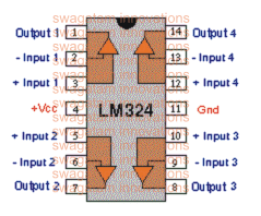
Circuit diagram:
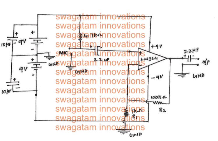
The power source is differential power supply, which consists of two 9V battery coupled with capacitors for smooth and noise less power. 2.2uF capacitor is for eliminating DC voltage entering the IC.
4.7K resistor helps powering the microphone. R1 and R2 is gain adjust resistor, you may calculate your own values. 2.2uf capacitor at the output is to truncate DC components.
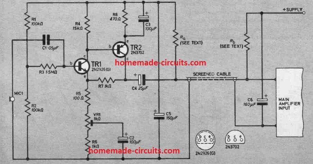
MIC Amplifier Circuit using Two Transistors
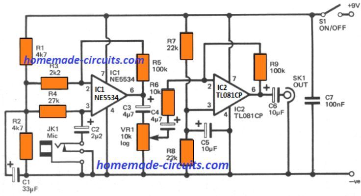
Crystal and high impedance dynamic microphones typically don't allow us to use it with long wires except when a certain coupling transformer is introduced. This is because hum noise and other stray pick-up can possibly get into the line. But a mini transformer, can be actually, too costly, particularly when high fidelity response is called for.
The below idea represents a technique which allows us to use preamplifier even at longer distances from the music or speech input source. This preamplifier is installed at the microphone end that works like an impedance matching transformer (high to low), and simultaneously features a handy voltage gain.
This circuit is unconventional because the power for the preamplifier is extracted from the main power amplifier and is supplied through the same common coaxial dynamic chord.
PREAMP SUPPLY
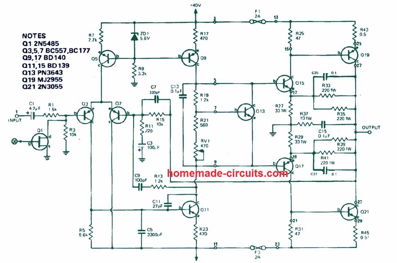
The following figure shows the basic operational details of the design.
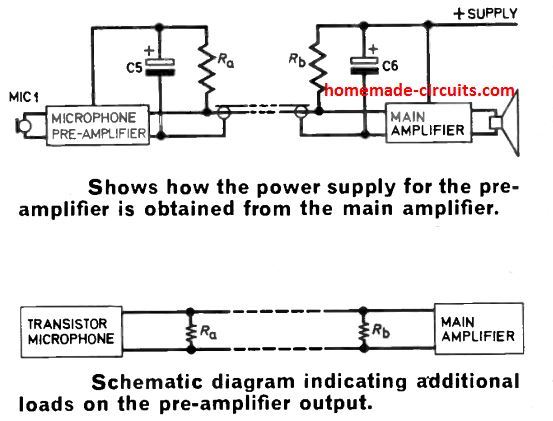
Let's first imagine the supply to the preamplifier coming from the main power amplifier unit.
Resistors Ra and Rb establish the voltage delivered to the preamplifier. Consequently, when the pre-amplifier draws a I amp current, the voltage getting at the preamplifier can be calculated by
V preamp = Vs - I(Ra + Rb)
where V is the supply voltage. The pre-amplifier detailed in this article was created to run using at 10V supply.
The current necessary is 2mA. If we consider the voltage tapping on the main amplifier is Vs and if Ra is made equal to Rb, the above equation simplifies to
Ra = Rb = 250(Vs - 10) ohms
It may be important to note at this stage that this specific approach of acquiring the supply voltage from the main amplifier must be applied only with low voltage transistor amplifiers having a highest voltage tapping of 50V.
The prototype had been intended for amplifiers working with a 20V supply. Any similar transistor amplifier having this type of supply can be employed.
Thefeore considering the amplifier supply is 20V then
Ra = Rb = 2.5K or simply 2.2K, even this value is not so critical, but not lower than this.

Questions & Answers
Dear Swagatam
Thanks for all these wonderful circuits. I have particular interest in Microphone circuit diagrams. My current necessity is related to a 12v microphone amplifier/ pre-amplifier which needs to be attached to a CCTV camera outside while its audio output shall travel through a distance through wire to be attached to a DVR input. (Total four circuits shall be build and installed by me for four cameras). I intend to install these Microphones in empty (LED bulb cameras upper plastic covers, i.e. like a parabola microphone to make it directional and also more sensitive) parabola. If time permits then please do suggest a circuit diagram with optional adjustment of sensitivity etc. I am good at soldering and have already made certain circuits do no issue in understanding it.
Regards
Thank you very much Sam,
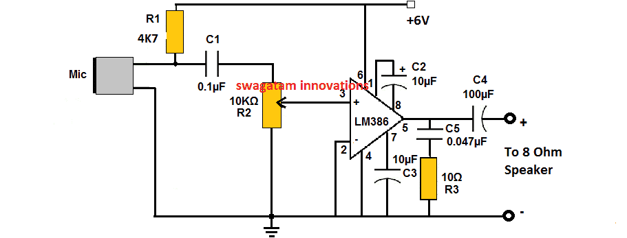
You can probably try the following circuit design for your application, using IC lm386.
The 10k pot can be used to adjust the volume control, and the C2 capacitor can be used to adjust the gain of the amplifier.
Moreover while searching web I have found a tear down of a known cheap CCTV camera mic by a author but he states that its performance is not good enough. I am not sure whether direct link posting is good or not but here it is (electroschematics.com/cctv-microphone-review/). U can check it urself and suggest. I am however sure that ur provided LM386 circuit has more performance being an op-amp. Plz. suggest as per my both comments. Regards
The circuit looks interesting however without testing it practically I can’t say much on it. I guess building the project using discrete parts can provide better results and could be more customizable.
Thanks, it was quick. I checked the circuit diagram but its stated for 6V. Moreover I have seen a similar circuit somewhere earlier but it also included a transistor stage with mic and then output was redirected to LM386. Are you sure that this particular circuit is sensitive enough and can work with long distance wire connections? Regards
The circuit can work with 12 v dc also…eventhough I haven’t tested the circuit myself I strongly believe it will work if it is wired correctly and also because it was referred from a reputable source. Since the lm386 is a high gain amplifier and can deliver upto 1 watt of output power it should be able sustain the signal through long wires. However since I am not sure how much power the DVR needs for processing the signal, it can be difficult for me to suggest in this regard.
Hi i tried doing this project but i don't get any output from the headphones.. I check the connections and it is fine. Do you think the problem is with my lm324?
Hi, try connecting a 10K resistor between the non-inverting (+) input of the opamp and the positive rail, see whether this helps or not.
Very very Thank u sir…
Output of this circuit mono. But in stereo amplifier there is 2 input….
If i connect in one channel only one spk will work….is there any circuit like mono to stereo connection….otherwise shall i connect the single output same to both left and right it will make any problem sir
you can make two such circuits by using the other spare opamps inside LM324 for enabling stereo connection
Shall i use 9.0.9v 500ma transformer to drive this circuit….
For using in 2.1 amplifier sir
will do
If any possible to make single power supply
your previously linked circuit of mic preamp is good and can be used…..single power supply can be made using another opamp as shown below
CONNECTED LM324 IC PIN NO.??????????
sir i need A Circuit. That Can Relay On Every 30 Second. After 30 Second
Sharoj, you can try a IC 4060 circuit for this.
thanks for great article
Our pleasure!
I am going to make it tooday …i hope it will be enough amlified to saturate the base of a transistor?
sure..yes it will do.
OWSUM ckt SIR!!!! just one confusion that should i connect gnd's of microphone,output and R1 to the gnd b/w that two 9V batteries ?
thanks Mujahid,
yes it needs to be connected to ground which is the junction between the (+) and (-) of the two supplies
Sir What Is Input voltage???
Where the Microphone Input ???
The 9V 0 9V is the supply input, and the MIC is the microphone input