In this post I have explained how to make a simple sine wave inverter using bubba oscillator sine wave generator. The idea ws requested by Mr. Ritwik Naudiyal.
Technical Specifications
I am a 4th year B.Tech Student Electrical Eng.
We are trying to make pure wave sine wave inverter using PWM and bubba oscillator for our Final project, also along with it a battery charging and auto cut off circuit would be needed
We want the inverter to work for day to day purposes. We would be grateful to you if u can give a working circuit fr this.
thank You!
Circuit Diagram
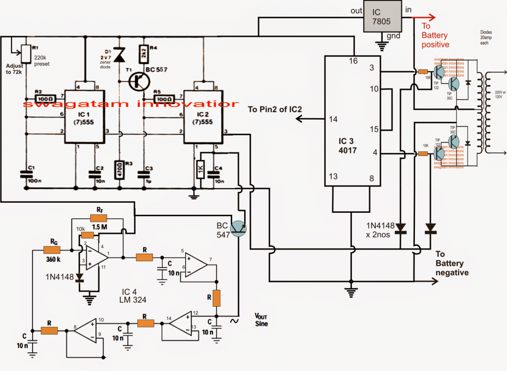
NOTE: Please use a Darlingtton pair for the BC547 connected with pin#5 of IC2 for efficient PWM conversion.
The Design
The proposed sine wave inverter using bubba oscillator may be understood with the help of the following points:
The stage comprising two 555 ICs are configured as PWM generators where IC1 forms a square pulse generator for the PWMs while IC2 forms the monostable PWM generator with respect to the modulation input applied at its pin5.
The sine wave modulation input at pin5 of IC2 is ahieved with the help of a bubba oscillator created by using four opamps from the IC LM324.
The generated sine wave pulses are fixed at precise 50 Hz and fed to pin5 of IC2 via a BJT common collector for further processing.
The 50 Hz Formula
The 50 Hz for the bubba oscillator is set by selecting R precisely with the help of the following formula:
f = 1/2(3.14)RC
IC2 compares the sine wave modulations at its pin5 with the square pulses at its pin2 and generates an equivalent PWM waveform at its pin3.
The flip flop stage reqired for switching the power stage is configured through a single IC 4017 whose outputs are appropriately integarted with the two high gain high current power BJT stage formed by Darlington TIP122 and TIP35.
The pin14 of the 4017 is clocked at around 200 Hz via pin3 of IC1 in order to achieve a 50 HZ switching across the power transistors.
The PWM modulation of the above 50 Hz switching is implemented with the help of the two 1N4148 diodes connected across the bases of the tIP122 and are switched in accordance with the PWM from pin3 of IC1
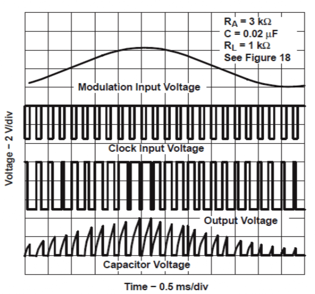
Assumed waveforms of the PWMs may be referred in the following image:
Waveform Bubba Oscillator



Questions & Answers
ello sir, thanks for the previous help in our major project. We have our evaluation on 20th. We need the stage wise functioning of the Sine-wave inverter using bubba-oscillator. Functioning of each circuit used like 4017, reasons of using this IC,why the connection has been made??Sir plz explain the circuit…we will be realy grateful to you https://3.bp.blogspot.com/…/bubba%2Boscillator%2Bsine%2Bwav…
Hello Ritwik, If possible I'll try to update it…in my free time.
The value of R for 50 Hz is very large when 10 n is used?
C will need to be converted to Farad before calculating….
What is the use of the last stage in the in the circuit,which uses the TIPs and the diodes in parallel?
What is the specification of the tranformer?
Is the value of R 3.2 M for 50 Hz??
the TIP transistors are for converting the PWM into high current oscillations so that the transformer primary can be induced with this for the required conversion…diodes are for protecting the transistors from transformer primary reverse back EMF
R should be 22k according to me…
Hello sir, thanx a lot for giving us the circuit for inverter.
I tried to simulate the circuit . I am not able to figure out how the value of R and C has been decided for frequency 50hz. As 50hz is not coming for 22k and 10n
according to the formula mentioned in the aforesaid comments!
Please explain it a bit sir, we have an evaluation for this circuit
Hello Vivek, try 10k for R and 0.03uF for C
sorry use 0.3uF for C….converting it into farad gives 0.000003F
therefore F = 1/2*3.14*10000*0.000003 = around 50 Hz
Good day,
Thanks for sharing the circuit to us. There is no batt voltage indicated, does it mean we can use any batt voltage such as 12v x 4batt (in series) = 48v? Does IC 7805 control DC voltage for the generator circuit? This sine wave inverter, does it mean pure sine wave inverter, as per waveform diagram above?
Thank a lot for explanation.
Good day, since the 7805 can tolerate only upto 35V, this voltage cannot be exceeded, however if an alternative method of stabilizing the voltage to the ICs is employed such as a common collector transistor stage, then probably upto 80V can be used in this circuit
I've tried the RC-filtered output generates sine 4017 wive. then be input LM324, LM324 and the output of a square wave instead of a sine wave. if the sine wave input to the LM324, LM324 whether the output sine wave?
it will be a PWM sine wave not a pure sine wave…
Down by ic4 there are 4 resistors without value, should they be 22k for 50hz?
you will need to calculate it using the given formula, C will be in farads in the formula
hello sir,
what is the value of R in the LM324 IC for the circuit above?
hello Timilehin, you'll have to calculate it with the help of the given formula.
This is very helpful for my senior project, so thank you! You explained it in simple terms that are easy to understand, and I appreciate that. My question is: How much power can this circuit provide safely?
thanks,
power of an inverter will be always equal or proportional to the transformer wattage and the AH rating of the battery, provided the mosfets are adequately rated
So for example,
If I need a 75 Watt inverter, I just need to make sure my transformer is rated for at least that much power, and the MOSFET's should be rated for 75 Watts as well? No higher power resistors or other components would be required?
Thank you!
that's correct, and of course the battery AH is also important, which should be around 5 times more the inverter consumption.
if the batt is 12V, then 75/12 = 6.25…and 6.25 x 5 = 31 AH approximately
other parts can be as is, no mods required
Thank you!!
One last question. The TIP35C's are rated at 120W but the TIP122's are rated at 2W. Should I switch out the TIP122's for more TIP35C's or do they serve a different function?
they serve different functions.
TIP35 can handle 25 x 100 = 2500 watts with sufficient heatsinking.
TIP122 can handle 5 x 100 = 500 watts if sufficiently heatsinked.
However in this design, TIP122s are positioned only for handling the base current of TIP35 and have no direct connection with the load, so no issues, everything is correctly configured…
Hi Again,
I'm trying to gain an understanding of how this circuit works so I can develop a test plan for it once I build it. How can I configure the IC4017 to generate a 60 Hz switching for the power transistors? Also, I'm a little confused how the sine wave from the bubba oscillator makes it's way to the transformer. I understand that the 4017 switches between the transistors, and the oscillator creates a sine wave, but the in-between steps are a little confusing to me still.
Thank you!
Austin
Hi,
three basic components are required for creating sine equivalent PWMs, viz : an opamp, a relatively fast triangle wave, and a relatively slower triangle wave (or a sinewave)…
https://www.homemade-circuits.com/2015/07/how-to-generate-sinewave-pwm.html
when these two signals are fed across the inputs of an opamp, the resultant at the output produces the required SPWMs.
here the IC2 becomes the opamp (comparator), pin7 and pin5 becomes its two inputs….fast triangle waves are generated and fed at its pin7 with the help of the square waves through IC1 at IC2 pin#2, and with the help of the associated R/C components at pin#7 of IC2.
Slow sine waves are achieved through the Bubba circuit and fed to pin#5 of IC2 via the BC547 emitter follower.
the fast triangle waves at pin#7 and slow sine waves at pin#5 of IC2 are compared internally and an equivalent PWM sine waves corresponding to the bubba output is generated at pin#3 of IC2.
this PWM is fed at the base of the transistors forcing them to conduct as per the PWM duty cycle, which are in turn are induced across the trafo winding with the same pattern.
The square wave frequency from IC1 which is fed at pin2 of IC2 is not crucial, and a little here and there does not make a difference therefore we dimension this frequency such that it serves two purpose simultaneously, it modulates the IC2 triangle waves and also feeds the 4017 input to help it to create a frequency at 50Hz or 60 Hz…for 50Hz we tune IC1 to generate 4 x 50 = 200Hz…for 60Hz, it would be 4x 60 = 240 Hz.
The preset associated with IC1 could be adjusted to achieve this frequency…the value 4 is found by counting the number of sequencing pinouts of the IC 4017
…the complex bubba circuit is actually not required…it can simply replaced by any easier triangle wave generator circuit.
hola Mr Swagatam, yo estoy montando el oscilador bubba para 120VAC 60 Hz pero como esta el diagrama no me funciona el IC1 ypor favor que valor de las resistencia de salida deben de ser la de el LM324
Gracias
hello victor, you can disconnect and isolate the bubba oscillator and check it separately to verify its functioning.
If you are having difficulty with the design, you can go through the following article for a comprehensive learning regarding the concept
http://www.ti.com/lit/an/sloa060/sloa060.pdf
sir can you please give me an example on how to calculate the output wattage for the inverter?
I would be grateful for your response.
thank you.
Angelous, always multiply the trafo winding voltage rating with its current rating….for example if the trafo is 12-0-12/10amp rated, then 12 x 10 = 120 watts
thanks sir
what about if thw power transistor are adding more to above inverter how to calculate the output wattage together with ouput wattagw of the trafo.
The transformer will accept and produce power only within its rated value, it will not accept anything above this regardless of how much the battery or the mosfet are pushing….however the battery voltage must match the trafo voltage otherwise the trafo will burn……also the load should not be beyond the trafo rating or else the trafo might again get damaged..
so sir do you mean that the output wattage or power of an inverter in your design is depend on a trafo voltage rating and amp rating… even if you add more power transistor there will no effect on the output wattage…
yes that's correct!
sir what is the advantage of the bubba oscillator compared to the other sine wave generator and what is it's disadvantages?
Angelous, all sine wave oscillators are good…but bubba is more balanced and stable
hi sir its me again,
sit what is the wattage value of all resistors that are used in the above inverter circuit design? could the 1/4 watt, 5% tolerance resistors can use in this design?
yes will do…
sir i have tried to solve the 50hz frequency for the bubba oscillator using the formula that you have disscused above by the use of 10k ohms R and a 0.3 C and i convert it into a 0.000003F but the result is really far from the desired frequency which is the result is only 0.0471.
can you please show me on how to solve it may be the error was from my own solving.
Angelous, you'll have to solve it yourself, because I hardly find time to answer the comments…
sir its me again In VM planning to simulate this circuit. but i have a question regarding the power transistor above. is the 4 transistor abount need heatsink and it is okay to place the 4 power transistor together in just one heatsink?
yes these transistors all will need large heatsinks..
sir what should be the the value of the 20amp diodes that used to protect the power transistor from back EMF?
it was not mentioned above.
Angelous, you can just specify 20 amp rating to the dealer, he will provide you the right one….
i have already asked the electronics store that are available here but there is no 20amp rating diode but only a 6amp diode that is available… so sir can i use 6amp diode ibstead of 20amp for the above circuit design?
sir the output voltage of this inverter circuit is 220v ac?
yes that's right
sir,one,more question. can I use a 6A diode as a power transistor protector from back EMF?
and what power transistor could I used other than that of TIP35?
thanks in advance.
if your transformer rating is below 6amp then you can use 6amp diodes
for 6amp current you can use 2N3055 transistors…
question: I always see you use a diode across output fets or transistors to protect them from the back emf from transformers but if I was to parallel the output fets would I need to use 2 diodes for each pair of Fet or would I just use 2 diodes
I think a single equivalent diode across any one of the parallel mosfets would do the job, moreover diodes are not designed to work in parallel due to their unequal forward voltage specs.
Ok thanks, and the anode goes to the source and the cathode goes to the drain
yes that's right
Question, If I was to parallel the FETS on this inverter ( ) would it just be gate to gate, source to source and drain to drain on each side, using an extra 10 ohm resistor at the gate of each FET?
preferably the gates must have there own 10 ohm resistors, the resistor ends could then be connected in parallel….source and drain can be connected directly in parallel across each other
ok thanks, I always wondered if an H-bridge couldnt be done with 4 N channel Fets instead of 2 N channel and 2 P channels… i that link I sent its actaully 4 N channels I dnt know if you have designs like that so I wanted to share so you could try it or prbably you already have designs like that.
thanks, yes I already have simpler versions of H-bridge inverters, using n-channel mosfets, moreover the design which you sent will require to be programmed and require a hex code etc.
I know you have H bridge with N channel fets but I thought it was a mixture of N and P…
Also I know the circuit needs to be programmed I have the code for it also, I ordered the driver chips so when they arrive I'm going to build it and test it out with 4 irfz44n, if that works I'll try 8.
I was referring to this circuit:
https://www.homemade-circuits.com/2014/01/simplest-full-bridge-inverter-circuit.html
the "load" could be replaced with a transformer for the required output
Oh kool Ill give it a try, is it PWM?
it's a simple square wave design, however PWM could be inserted across the low side mosfet gates
PLease what is the standard rating for the transformer
what is the standard load you would be using?
I actually built the circuit in the link I provided above and from the arduino I got 50hz but from the transformers output I got 2khz, I am wondering what would cause that I used the correct value capacitors, 2 diodes are there that has no value so I used 1n4007.
I was thinking about building a low pass filter to get 50hz which I would just use a 330 ohm resistor and a 10uf capacitor but I was seeking your advice to identify the problem causing that high frequency.
It's causing due to the superimposition of the PWM frequency over the 50Hz pulses, please check through an oscilloscope for understanding the exact situation of the output….using the low pass will simply block the PWMs.
OK the scope I have is a portable scope do nano
I'll provide a drop box link to the set up I have and the readings, also the scope is connected to the primary of the transformer because I don't think it can handle 250v
https://www.dropbox.com/sc/g741oldx01s7cu6/AAA6iCJQXNQo-ZafHuOUSNpIa
Also the more I change the time division on the scope it's either the frequency doesn't show or it changes in value so that's why I used my multimeter to test frequency.
check the frequency without the PWM feed at the base of the transistors, it should now show 50Hz, if not then either the IC1 is wrongly set or your meter could be malfunctioning
A similar circuit was verified for its waveform by one of the readers, where he could capture the details across the output of the trafo, you can see the images in this article….so it think the results would be quite similar for the above design too
https://www.homemade-circuits.com/2013/10/modified-sine-wave-inverter-circuit.html
I am having difficulty in understanding your waveform results….
sorry, I am assuming you have applied the PWM section as described in the above article, did you? if not then the above linked article and my suggestions could be irrelevant for your case and the issue can be somewhere else…
The pics I sent you were from the test I made before you replied so the PWM section was still applied to the gate of the FETS I will remove them now and send results soon.
I just tested the circuit without feeding Pwm to the gate of the Fets
https://www.dropbox.com/sc/eg05wv8wdk1wr99/AAAmZ-qwYG-SRHcHdqDG_hY0a
I got 51hz
But while the Pwm is disconnected from the Fets if I connect the transformer there is no frequency at the drain of the transistors nor at the secondary of the transformer.
If I connect the transformer and also reconnect the Pwm feeds then the frequency goes up to 2.5 or up to 3khz on the secondary of the transformer and and the primary frequency is 1.8khz.
One other thing, I don't have any 10ohms resistors so I used 220ohms for the gate of the fets could that be what's causing the high frequency.
I am assuming that you have built the circuit discussed in the above "bubba sine wave" article.
if you are getting 50 Hz at the gate of the mosfet or power transistor then the transformer should produce the required AC and frequency at the output…
gate resistance may not be the cause, still try using smaller resistances below 50 Ohms instead of 220 ohms.
connect a load at the trafo output with this 50 Hz operation without PWM and check the response
I realize why you didn't understand fully what I was saying, I sent this link to you but seems It didn't go through at the beginning of the messages.
https://www.dropbox.com/sh/6di2i4tvak0g7d1/AAC2HNF3qCmzU85XvVRFIPXya?dl=0
thats the schematic I was trying and was asking for your assistance.
I got 51hz without PWM feeds to gates of Fets
But while the Pwm is disconnected from the Fets if I connect the transformer there is no frequency at the drain of the transistors nor at the secondary of the transformer, also no voltage across the drains which would go to the secondary of the transformer.
If I connect the transformer and also reconnect the Pwm feeds then the frequency goes up to 2.5 or up to 3khz on the secondary of the transformer and and the primary frequency is 1.8khz. and at that time I would get 10.8v accross the drains of the FETS.
It will be difficult for me to comment on the linked circuit since it's not designed by me and it's based on Microcontroller.
By the way I cannot see any PWM feed from the IC, it's just the alternate square wave outputs which are been fed to the half bridge drivers. so if you are disabling this the entire driver circuit is going to shut down
ok as I said previously from the 2 pins from the micro-controller I am getting 50hz, but when I connect the meter to the secondary of the transformer I get 1.8khz and 3khz from the secondary, I was just asking what could cause that, when I removed Pwm feed what I actually did was to disconnect the wire connected to the gate of the Fets in which I got 51hz.
So i was wondering what the problem could be but I understand that you didnt design it I just like to try new circuits and was just seeking advice on fixing that problem.
if the transformer primary is oscillating at 50 Hz then the secondary would oscillate at the same rate too, I think your frequency meter could be malfunctioning, check your home AC outlet frequency with the same meter, see whether it shows 50Hz or some other value….
Hola Swagatam estoy intentando por todos lado hacer esta montaje oscilador bubba pero no funciona los Ic1 y Ic2 que pulso deben tener y he cambiado las R y los C del IC4 pero nada
por favor puede usted ayudarme si hay otro circuito o como mejoro este diagrama
Gracias
Hola Victor, could you please translate your comment in English so that we can all understand it?…
circuitos otimos ´muito bom
Thank you!!
SHOW DE BOLA
Hi what is the output power and current for this? What kind of loads can it drive?
It will depend on the transformer wattage rating, and battery Ah rating. Mosfets can be replaced as per these maximum wattage ratings.
Load can be any type of load
Thank you.I really appreciate that you actually respond to all of the questions and your circuits are very useful for my project.
You are most welcome Claudia!
Hi I have tried to simulate the circuit as it is, on proteus, but I am not getting any output from the bubba oscillator and hence none from th tx.I have tried to attach the circuit on email but I am not sure if it will be received.
Hi, I am sorry I can’t troubleshoot simulator results, but I can assure you that if you build this practically and correctly it will work, 100%
Thanks sir,
Can I build a 3000-4000watts inverter with this circuit? Can I use 24v battery input for such power?
Hi foxy, you can definitely do it by appropriately upgrading the mosfet and the transformer specs.
Can I replace the cd4017 with sg3524
yes you can!
I very much enjoy your circuit ideas but I would like to raise one or two comments about the Bubba oscillator included in one of your inverter circuits.
Firstly according to the circuit the timing capacitors should be 10nF is this an error as in all other circuits I have seen they are 100nF?
Secondly I found that the circuit would not oscillate unless the 350K resistor was removed. The resistor value appears to be correct as it appears in other circuits I have seen.
When this is done and the capacitors change to 100nF it begins to oscillate and with 27K resistors it give an output of around 51HZ which is as close as I can get with preferred value resistors.
However, interestingly enough the sine wave now emerges from Pin2 of the OP AMPs and not 12 as in the circuit. I know that it is phase shifting because I get a cosine wave at one point and a square wave at another.
Do you have any suggestions why this should be?
Thank you for the suggestions, you may be correct….Actually the bubba circuit was taken from some other source, so i am not sure about its accuracy.
For accurate bubba circuit calculations you can refer to the following article, which can be applied in the above sine wave inverter design:
https://www.homemade-circuits.com/phase-shift-oscillators-wien-bridge-buffered-quadrature-bubba/
Swagatam,
Thank you for your response to my suggestions and observations and I visited the site you requested me to go to which confirms the original configuration.
Since my last e-mail I have now done some extensive tests on the Bubba oscillator circuit and have come to the following conclusions.
Bubba oscillators work well at higher frequencies i.e. in the kHz range, however, when you start to ask them to work at lower frequencies it is necessary to increase the value of the timing resistors (R). Because Op.Amps are not known for their amplification characteristics the increased resistance together with the 360K resistor blocks the signal path and the circuit does not oscillate. Removing the 360K resistor i.e. shorting it out reduces the effective overall resistance and it begins to work.
In my tests I have found that a preferred value of 27K for (R) is as close as you are going to get to 50Hz and the oscillator produces an output of around 51-52Hz. Obviously you could replace the resistors with trim pots but this would then require accurate measurement and adjustment which I do not think is worth it. The mains frequency on the grid is drifting about anyway and a few Hz is not going to make much difference to the output of the inverter.
You could tighten the tolerances of the resistors (R) but I think that this would be overkill.
Taking out the 360K resistor produces a displacement of the phase shift in the circuit with the result that the sine wave now appears at Pin 2 and not Pin 12 in the original configuration but the sine wave is of good quality and reasonable amplitude.
I hope that my contribution is of assistance
Thank you very much Paul, I appreciate the valuable information that you have shared here, I am sure the other visitors will find this useful too!
Ic3(cd4017) in the above circuit being a counter, did not work in one of the inverter circuit I tried it with. what if I replace it with cd4013 will it work as intended.?
Thanks in advance.
4017 is s perfect IC for inveter application, you can also try 4013, but if 4017 did not work then 4013 won’t work either for you.
You can see the first two examples in the below given link:
https://www.homemade-circuits.com/modified-sine-wave-inverter-circuit-2/
To me the bubba circuit is just a west because pin five of a 555 timer ic is the output control pin which a may voltage feeding into the pin will do same work that bubba circuit is doing
How can I use egs002 with out shot down and blinking
I think those are in-built features of the board and it cannot be removed or disabled.
1. What is it’s power rating?
2. How do I increase the output power, if I need to?
Power rating can be adjusted by upgrading the TIP35 rating, or using MOSFETs instead.