• Skip to main content
  • Skip to primary sidebar

Homemade Circuit Projects

Need circuit help? Post them in the comments! I've answered over 50,000!

Blog | Categories | About | Hire Me | Contact | Calculators-online
You are here: Home / Sensors and Detectors / Simplest Metal Detector Using a Single CMOS IC 4093

Simplest Metal Detector Using a Single CMOS IC 4093

Last Updated on November 11, 2026 by Swagatam Leave a Comment

In this post I have explained a simple metal detector circuit having a decent sensitivity using a single CMOS IC 4093, as I have explained below.

Table of Contents
  • How it Works
    • Coil Winding Specifications
    • How to Set up the Circuit
      • Circuit Diagram
    • IC 4093 pinouts
  • Parts List
  • How to Set up the Circuit
  • Troubleshooting Tips
  • Frequently Asked Questions

How it Works

The circuit functioning may be understood with the following points:

The proposed metal detector uses a 4093 quad Schmitt NAND IC and a search coil along with a switch and batteries for power.

A lead from IC1d pin 11 connects to MW radio aerial, or another process would be to warp around the radio. The BFO switch if present in the radio must be turned on.

The resistance of rapid change in voltage – known as reactance, delays the logic level at ICI pin 10 back to its input pins 1 and 2, and is further delayed through propagation delays within 4093 IC.

This entire process results into rapid oscillations of around 2 MHz, is picked up by a Medium Wave radio.

2 MHz is out of range for Medium Waves, but a MV radio can accept the harmonics of 2 MHz frequency. The process of winding of the coil is not complicated.

Coil Winding Specifications

The prototype uses 50 turns of 22 awg/30 swg (0.315 mm) enameled copper wire, wounded on a 4.7"/120 mm former, and then wrapped in an insulation tape.

The coil is then connected to 0V.A Faraday shield which is a tin foil acting as a wrapper around the coil. This process leaves a small gap and care should be taken so that the foil does not wrap the entire circumference of the coil. An insulation tape is again used to wrap the Faraday shield.

A connection can be established to the Faraday shield with a piece of stiff wire wrapper around the shield, before adding the tape.

An ideal scenario would be to wire the circuit with twin-core or microphone cable, and connect the screen to the Faraday shield.

How to Set up the Circuit

Setting up the metal detector involves switching on the MW radio to pick up a whistle on a harmonic of 2 MHz.

However to note, not all harmonic works best, only the one which suits need to be used. With a suitable harmonic and the metal will alter the tone of a whistle.

A metal detector detects a large coin at 80 to 90 mm, which is quote good for a BFO detector. It can even identify discrimination between ferrous and non-ferrous metals with the rise or fall in tone.

Submitted By: DhrubaJyoti Biswas

Circuit Diagram
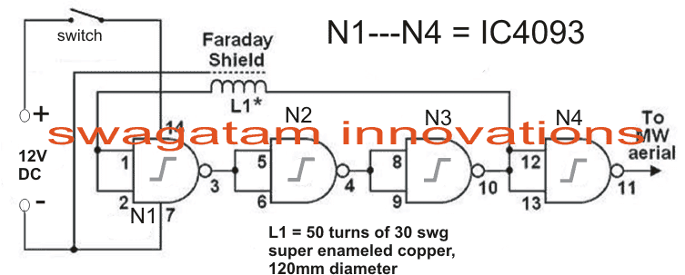
BFO Metal Detector Circuit using IC 4093

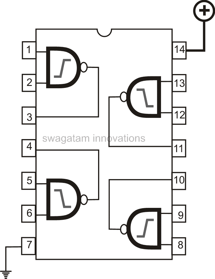
IC 4093 pinouts

IC 4093 pinout

Parts List

ComponentSpecification / DescriptionQuantity
ICCD4093 Quad Schmitt NAND Gate IC1
Search Coil50 turns of 30 SWG enameled copper wire on 120mm former with Faraday shield1
Radio ReceiverPortable Medium Wave (MW) Radio1
Resistors / CapacitorsStandard supporting resistors and decoupling capacitorsSet
Power Supply9V battery or DC supply1

How to Set up the Circuit

Power on the circuit and tune a nearby Medium Wave (MW) radio to pick up the oscillator whistle on a harmonic of 2 MHz. Adjust the radio tuning until a clear tone is heard. Bring a coin or metal object close to the search coil; the pitch of the whistle will change noticeably. A larger coin can typically be detected at 80 to 90 mm, and you can observe a rising or falling tone variation depending on whether the metal is ferrous or non-ferrous.

Troubleshooting Tips

No whistle heard on radio: Check battery voltage, verify IC pin connections and ensure the radio is tuned to the correct MW frequency band where the harmonic falls.

Tone drifts or triggers from hand proximity: Make sure the Faraday shield is properly wrapped around the search coil and connected to 0V ground.

Very weak metal detection: Verify that 50 turn coil is wound neatly on 120 mm former and that connection are secure.

Frequently Asked Questions

Can I use any other NAND gate IC instead of CD4093?

CD4093 includes built in Schmitt trigger inputs which are important for clean, stable high frequency oscillation in this BFO setup. Standard NAND gate without Schmitt trigger may not oscillate reliably,

Does this circuit require a speaker connected directly to it?

No, this design acts as a miniature transmitter whose harmonic signal is picked up and heard through a nearby Medium Wave radio speaker.

Can it distinguish between ferrous and non ferrous metals?

Yes, depending on target's magnetic and conductive properties, frequency shift can cause the audio whistle to rise or fall differently.

Filed Under: Sensors and Detectors Tagged With: 4093, CMOS, Detector, Metal, Simplest, Single

About Swagatam

I am an electronics engineer and doing practical hands-on work from more than 15 years now. Building real circuits, testing them and also making PCB layouts by myself. I really love doing all these things like inventing something new, designing electronics and also helping other people like hobby guys who want to make their own cool circuits at home.

And that is the main reason why I started this website homemade-circuits.com, to share different types of circuit ideas..

If you are having any kind of doubt or question related to circuits then just write down your question in the comment box below, I am like always checking, so I guarantee I will reply you for sure!

Previous Post: « Single Transistor BFO Metal Detector Circuit
Next Post: Metal Detector using Magnetic Absorption »

Reader Interactions

Need Help? Please Leave a Comment! We value your input—Kindly keep it relevant to the above topic! Cancel reply

Your email address will not be published. Required fields are marked *

Primary Sidebar

Categories

  • Arduino Projects (95)
  • Audio and Amplifier Projects (134)
  • Automation Projects (18)
  • Automobile Electronics (104)
  • Battery Charger Circuits (90)
  • Datasheets and Components (109)
  • Electronics Theory (153)
  • Energy from Magnets and Earth (43)
  • Games and Sports Projects (11)
  • Grid and 3-Phase (20)
  • Health related Projects (27)
  • Home Electrical Circuits (13)
  • Indicator Circuits (16)
  • Inverter Circuits (111)
  • Lamps and Lights (183)
  • Meters and Testers (72)
  • Mini Projects (28)
  • Motor Controller (68)
  • Oscillator Circuits (30)
  • Pets and Pests (15)
  • Power Supply Circuits (92)
  • Remote Control Circuits (50)
  • Security and Alarm (65)
  • Sensors and Detectors (123)
  • SMPS and Converters (52)
  • Solar Controller Circuits (63)
  • Temperature Controllers (44)
  • Timer and Delay Relay (51)
  • Voltage Control and Protection (44)
  • Water Controller (37)
  • Wireless Circuits (31)

People also Search

555 Circuits | 741 Circuits | LM324 Circuits | LM338 Circuits | 4017 Circuits | Ultrasonic Projects | SMPS Projects | Christmas Projects | MOSFETs | Radio Circuits | Laser Circuits | PIR Projects |

My YouTube Channel

Circuit Simulator: Draw and Simulate Schematics

circuit simulator image

Subscribe to get New Circuits in your Email

Other Links

  • Privacy Policy
  • Cookie Policy
  • Disclaimer
  • Copyright
  • Videos
  • Sitemap

Recent Comments

  • Swagatam on IC LM393 Complete Datasheet with Circuit Diagram
  • Swagatam on Induction Heater Circuit Using IGBT (Tested)
  • Swagatam on Calculate Battery, Transformer, MOSFET in Inverter
  • Swagatam on Rat Repellent Circuit Diagram
  • Jeff on IC LM393 Complete Datasheet with Circuit Diagram

Social Profiles

  • Twitter
  • YouTube
  • Instagram
  • Pinterest
  • My Facebook-Page
  • Stack Exchange
  • Linkedin

Calculators

  • ZVS Induction Heater + Tank Calculator Tool
  • Zener Diode Calculator
  • Wire Current and Thickness Calculator (Ampacity Calculator)
  • Resistive Voltage Divider Calculator
  • Transistor Base Resistor Calculator
  • Transistor Astable Multivibrator Calculator
  • TL431 Calculator
  • Solar Panel, Inverter, Battery Calculator
  • Ferrite Core Air Gap Calculator Tool
  • Parallel MOSFET Calculator Tool: How to Connect MOSFETs in Parallel Safely
  • LC Resonance Calculator for EV Battery Charger Circuits
  • LED String Series Resistor Calculator
  • PFC (Power Factor Correction) Calculator Tool: 3kW
  • Passive Power Factor Correction (PFC) Calculator
  • LM567 IC Calculator Tool
  • SMPS Flyback Boost Converter Calculator
  • Shunt Resistor Calculator for Ammeters
  • SCR and Triac Gate Resistor Calculator
  • Battery Back up Time Calculator
  • Boost Converter Calculator (Non-Isolated)
  • Bootstrap Capacitor Calculator
  • Buck Converter Calculator
  • Buck-Boost Converter Calculator
  • Capacitance Reactance Calculator
  • DCM Flyback Transformer & Wire Gauge Wire Size Calculator Tool
  • Filter Capacitor Calculator
  • IC 4047 Calculator (Frequency and PWM)
  • IC 4060 Calculator
  • IC 555 Astable Calculator
  • IC 555 Monostable Calculator
  • IC SG3525, SG3524 Calculator
  • Inductance Calculator
  • Induction Heater Inductor and Resonant Frequency Calculator
  • Induction Heater Work Coil Calculator
  • Inverter LC Filter Calculator
  • LC Resonance Calculator
  • LED Current Calculator
  • LM317, LM338, LM396 Calculator
  • NAND/NOT Gate RC Values Calculator
  • NOT, NAND Gate Frequency Calculator
  • Notch Filter Calculator Tool
  • Ohm’s Law Calculator
  • Phase Angle Phase Shift Calculator
  • Power Factor (PF) Calculator
  • RC Filter Calculator
  • Reactance Calculator
  • Sine Table Calculator for SPWM Arduino Code
  • Small Signal Transistor(BJT) and Diode Quick Datasheet
  • SMPS Calculator for Toroidal Ferrite Transformers
  • SMPS Flyback Transformer Calculator – Design by Target Duty Cycle
  • TL431 Calculator
  • Op-Amp Hysteresis Resistor Calculator

© 2026 · Swagatam Innovations