Behind the detection technology of this metal detector circuit is a sensor that identifies the existence of ferrous and non-ferrous metals by absorbing the magnetic energy.
This magnetic field is produced by an inductor which a part of a modified oscillator circuit. The moment a metal object is approached to the magnetic field, sufficient magnetic energy is absorbed to halt the oscillator.
How the Circuit Works
Figure below depicts the Colpitt’s oscillator that fires around 70 kHz. Inductor L1 functions as a sensor due to the emitter resistor’s (R1) large value and eventually, the oscillator just works.
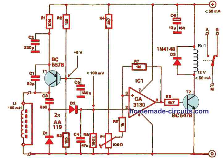
This is favourable because alternatively the losses in the regulated circuit will be reloaded by the transistor. D1 and D2 will rectify the oscillating output and the subsequent direct voltage is directly applied to the inverting input of Schmitt trigger IC1.
Once the voltage dips below the value at pin 3 which is represented by P1, the output will switch to a high, energizing the relay. We recommend constructing the detector on a PCB as shown in the figure below.
The actual purpose of inductor L1 was not to mount in on the PCB. In case the oscillator does not immediately start at whatever setting the P1 was engaged, you must bring down the value of R1.
Alternatively, if the oscillator continues detecting even when a metal object is held close to L1, the R1 value must be increased.
You need to start with the wiper of P1 to earth and control the preset so the relay does not operate at all. When you need a little more sensitivity, increase the wiper a tad more.
The energising of the relay principally dictates the current consumption and for most cases, it is not more

Need Help? Please Leave a Comment! We value your input—Kindly keep it relevant to the above topic!