In this post I have explained 4 innovative automatic staircase lamp controller circuits which will automatically switch ON and OFF the staircase lamps in response to an external trigger.
We will discuss 4 concepts here, which are as follows:
- PIR Based Circuit
- Foot Activated Circuit
- Clap Operated Circuit
- LM567 proximity detector based circuit
1) Automatic Staircase Lamp Circuit using PIR
The first automatic staircase light circuit describes a simple PIR based circuit which detects an approaching user and switches ON the staircase lamp automatically.
When the user has left the staircase, the PIR detects the absence of a human being and switches OFF the staircase lamp automatically.
Components required:
- PIR module: It is a pre-made module that includes a PIR sensor with three pinouts - Vcc, ground, and OUT.
- 1K resistor: This resistor is used for current limiting.
- BC547 transistor: It is a general-purpose NPN transistor.
- 12V relay coil: The coil is used to control the AC lamp.
- 1N4007 diode: It acts as a freewheeling diode to protect the transistor from reverse electromotive force (EMF) from the relay coil.
- 12V DC power supply: It can be a 12V SMPS (Switched Mode Power Supply) or a transformer-based power supply.
How to Build
The complete circuit diagram of the automatic staircase lamp using a PIR is shown below:
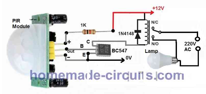
Connect the Vcc pin of the PIR module to the positive terminal of the 12V DC power supply through the 1K resistor.
Connect the Ground pin of the PIR module to the emitter pin of the BC547 transistor. Also, connect this ground line to the negative or 0V of the 12V DC power supply.
Connect the OUT pin of the PIR module to the base pin of the BC547 transistor.
Connect the collector pin of the BC547 transistor to one end of the relay coil.
Connect the other end of the relay coil to the positive terminal of the 12V DC power supply.
Connect the cathode (marked with a line) of the 1N4007 diode to the positive terminal of the relay coil. Connect the anode of the diode to the collector pin of the BC547 transistor.
Power supply:
Use a 12V DC power supply to provide power to the circuit. It can be a 12V SMPS or a transformer-based power supply.
Operation:
Place the entire unit somewhere along the desired staircase path.
When a user approaches the staircase, the PIR sensor detects the presence of a human being and activates the circuit.
The PIR module's OUT pin goes high, and this signal is applied to the base of the BC547 transistor.
The BC547 transistor conducts, allowing current to flow through the relay coil.
The relay coil energizes, closing its contacts, and turning on the connected AC lamp automatically.
When the user leaves the stairway, the PIR sensor detects the absence of a human being.
The OUT pin of the PIR module goes low, cutting off the base current of the BC547 transistor.
The transistor stops conducting, and the relay coil de-energizes, opening its contacts and turning off the AC lamp.
This way, the circuit automatically controls the staircase light based on the presence or absence of a user detected by the PIR sensor.
2) Foot Activated Staircase Light Circuit
The second concept below explains a simple foot activated staircase light circuit comprising of a chain of LEDs which activate sequentially in response to each climbed step. The idea was requested by Mr. Dwayne.
Circuit Objectives and Requirements
- I'm hoping you can help me. I am hoping to make a LED light up staircase.
- Using LED light strips on each step I would like the circuit to be activated by a Pressure switch on the first step (and top step for coming back down). There are 2 ways I would like it to work.
- Option 1:
- The LED's to light up in a delay, step-by-step with say a 1 or 2 second delay between each step illuminating. But the lights staying on until the last light is illuminated, then they all turn off together maybe 3 or 4 seconds after the last step is illuminated.
- Option 2:
- I imagine somewhat easier and more simple would be;
The LED's to all activate at the same time upon being activated by the pressure switch. Remaining on for 10 or 15 seconds then all turning off together. - I have not done anything like this before so would really appreciate all possible support and information.
Many thanks in advance.
Using separate Sensors and LEDs for Sequential Lighting
The proposed foot activated staircase LED light circuit can be implemented in two unique ways:
1) The first idea allows a chain of LEDs installed across the length of the entire staircase to be lit sequentially, one after the other in response to each step climbed by the visitor.
2) The second concept allows all the LEDs to light up together when the visitors steps on the first stair, and the light is shut off as soon as the visitor has crossed the last uppermost
The first concept can be implemented by installing the following circuit across each of the stair steps:
Circuit Diagram
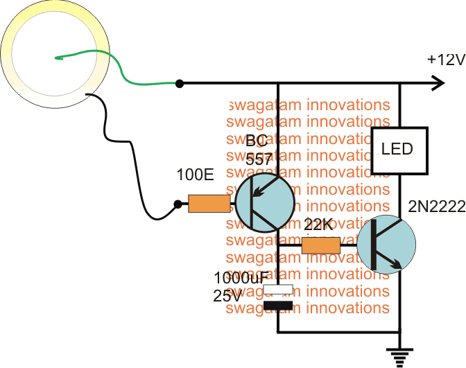
The piezo transducer in the design is used as a pressure to electricity converter. The piezo element is supposed to be embedded within each of the stairs, while each of the associated circuitry to be wired within the nearby wall, along with the LED.
Once done, whenever someone steps on the staircases, the relevant piezo generates a small electric pulse in response to the vibration, which in turn triggers the 2N2222 delay OFF timer stage, and the LED which now lights up for a few seconds and then automatically shuts off.
The above action goes on happening as the visitor climbs the steps, illuminating and shutting off each subsequent LED in a sequential manner.
Using a Flip Flop and Delay Timer for Creating a String Light Effect
The second foot activated staircase light circuit idea can be enforced by installing the following across the first and the last staircases.
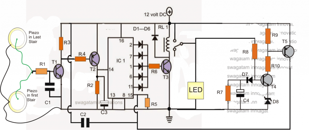
Parts List
- R1 = 100 ohms
- R2, R3, R4, R5, R6, R9, R10 = 10K
- R7 = 100K
- R8 = 330K
- C1, C2 = 0.22uF
- C3 = 1uF/25V
- C4 = 470uF/25V
- D1----D7 = 1N4148
- D8 = 3V zener diode
- IC1 = 4017 IC
- T1, T3, T4 = BC547
- T2, T5 = BC557
- Relay = 12V, 400 ohm
Circuit Operation
In the above design two piezo transducers can be seen embedded across the first and the last staircases.
When the first piezo is hit by the foot of the visitor, the tiny electrical pulses generated from the piezo is amplified by the T1/T2 stage and applied at pin#14 of the IC 4017, which is rigged as a flip flop stage here.
The trigger allows the 4017 to toggle ON the relay driver stage which lights up the LED lamp.
The process also triggers a delay ON timer circuit which begins counting the delay for which it is been fixed.
In the meantime the user continues climbing the steps until he reaches the upper most step, and his foot activates the second piezo transducer, which yet again toggles the IC 4017, but this time to switch OFF the relay driver stage and the LED.
In case the user decides not the climb the steps and returns back or takes abnormally too long to complete his journey across the steps, the delay timer comprising T3/T4 switches ON into action and resets the IC 4017 IC causing the LED to switch OFF.
If you have more innovative suggestions to improve the discussed foot activated staircase LED light circuit, please use the comment box for expressing the same.
3) Simple Clap Operated Staircase Lamp Circuit
The third idea below discusses how to make a simple clap operated stairway light switch circuit for enabling a brief switch ON of the lights while the user crosses the lane, and thus save electricity. The automatic lamp switch ON happens in response to a clap sound by the user.
Introduction
Stairways, corridors or small indoor passages often tend to be dark throughout the day irrespective of the outdoor ambient light conditions. Therefore keeping such passages illuminated all the the time becomes imperative, however this leads to unnecessary wastage of electricity.
An innovative way of solving this problem has been discussed in this article, by employing a clap operated momentary light switch circuit.
The circuit diagram may be understood as follows:
How the Circuit Work
The idea is to switch ON the connected lights in the corridor through a clap sound, whenever the involved passage is utilized.
The clap sound triggers the circuit and keeps the connected lights switched ON for a few seconds or until the predetermined time is lapsed, after which the lights are automatically switched OFF.
The configuration is actually a transistor based clap switch, but without a flip flop stage, rather the flip flop is replaced by a delay OFF timer stage for the necessary switching and sustaining of the lights for a fixed predetermined period.
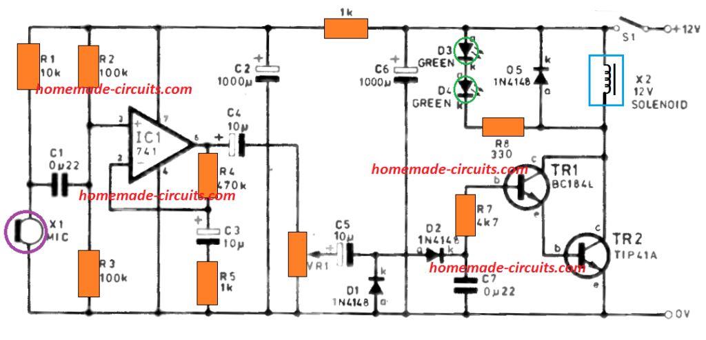
The stage as usual includes a sound sensor stage consisting of a mic and the subsequent transistor amplifier stage using a couple BC547 transistors.
The next stage consists of the PNP transistor BC557 which receives the signals amplified from the first stage via the 47uF capacitor.
The fed signals are further amplified to much greater levels for triggering the final LED driver stage.
The LED driver stage consists of a group of white LEDs which provides enough light for illuminating a small passage premise.
The two 39K resistors and the 220uF capacitors form the basic delay OFF timer and decides for how many seconds the driver stage remains ON with the LEDs lit.
The power to the circuit can be either applied by incorporating a standard transformer/bridge AC/DC adapter or if the circuit needs to be more compact, a transformerless power supply may be included with the below shown circuit.
All the NPN transistors are BC547B and the single PNP transistor is a BC557B, LEDs are ordinary 5mm high efficiency white LEDs.
The coil can be of any type, a 100mH choke will also do, it's introduced in order to keep the circuit stable and for avoiding self oscillations.
Circuit Diagram

Another Clap operated Stairway Switch Circuit
Here's another simpler design that you can try for the proposed clap operated staircase lighting system. It's a tested design and is more accurate and easier to build than the previous circuit.

4) Automatic Staircase Lamp using LM567 Proximity Sensor Circuit
The fourth concept relates a simple automatic infrared controlled staircase lamp circuit using a proximity detector circuit. The circuit switches ON only during the presence of a passer-by and switches OFF automatically after a predetermined delay once the occupant vacates the corridor . The idea was requested by Mr. Sriram.
Technical Specifications
Hai, Recently while i was searching for automatic motor circuit i got ur blog. U r doing great work. Now I am following ur blog. I am planning to fit a automatic staircase light in my house staircase.
But i don't have enough knowledge to make a own circuit. I am not able to find a circuit according to my need i the internet. so i need ur help to design a circuit according to my specifications. Here the specifications :---
The circuit can work at 5v DC. A single circuit should contain 2 sensors. One sensor will be fixed at the first staircase, another one at the last staircase.
The circuit should contain a relay to get output of 220v Ac. So that i can connect a CFL bulb in that circuit. If i cross any one of the sensor means the bulb should glow for 2 mins and it should switch off.
And another thing is , suppose I crossed any one of the sensor, the bulb is started glowing for 2 mins. with in that 2 mins if I cross the another sensor means the time should reset for 2 mins and the bulb should glow for 2 mins more and it should switch off.
The bulb should not flicker while the time is reset. Then a override switch switch should be there to switch on the bulb manually ( like a SPDT switch, up for sensor, center off, down means manual switch on the bulb). I hope u can help me.
The Design
The project is primarily intended to save unnecessary wastage of electricity by using a smart automatic sensor equipped lighting system as I have explained below:
As shown in the figure below, the proposed circuit idea of an automatic Infrared staircase light is fundamentally made up of two accurate proximity sensor stages coupled with each other for executing the above actions.
Each proximity sensor includes the IC LM567 frequency decoder chips which are rigged with a particular frequency set by the corresponding R3/C2 networks.
Each of the ICs become locked at these set frequencies which also become the transmitting frequencies for the respective ICs.
The above set frequencies drive the relevant Infrared photo diodes which transmit the coded IR waves for detecting an obstacle or human movement across the preferred zone.
On detection of an "obstacle" the IR waves are reflected back from the object and received by another photodiode positioned optimally for the procedures.
Since the received IR waves are set with the correct specified frequency of the IC, the received signals from D2 is readily accepted by the IC which in turn allows its pin8 to go low with the response.
The low response from pin8 of either of the LM567 ICs is fed to the trigger pin2 of a IC 555 monostable multivibrator (MMV) circuit.
The MMV responds to the trigger and activates its output to a high forcing the connected relay to switch ON itself, and the connected load across its contacts.
R9/C5 may be appropriately selected for obtaining the required amount of delay for the relay ON state and the lights.
T3 makes sure that the MMV timing initiates only after the human presence is eliminated, which ensures that the lights never goes off as long as the premise may be in an occupied condition.
The two sensor modules across the left of the corresponding LM567 ICs may be stationed across the ends of the staircase, as proposed, for implementing the desired procedures.
Circuit Diagram


Questions & Answers
All these are great projects but they don’t help in my situation, can you help with my case? My stairwell light is controlled by three different 120VAC switches (one at the bottom and two by the bedrooms upstairs) my kids forget to turn the light off 99% of the time and we know how the power bill adds up. Is it possible to create a circuit to be installed at the lightbulb ???? input, activated by any of the three switches that would cut off power to the bulb in 3-5 minutes? The bulb in use at this time is a non-dimmable LED but could be replaced in a pinch by a 40-60W incandescent or a compact fluorescent. I’ve tried designing a circuit but the second part of the problem kills my design. This bulb is mounted on a fan without a separate circuit. I need to bypass (keep the circuit on) if the built-in 3-speed fan switch is activated.
Thanks.
Hi, thanks.
As far as I have understood, you need a delay OFF timer which will switch off a lamp after 3-5 minutes.
So, whenever the lamps are switched ON manually, it will light up and then switch OFF automatically after the specified time.
This is entirely possible, but you will need to install each of these circuits to each of the lamps separately.
Please let me know if this suits you…
Thanks for the quick reply. There is only one light that can be turned on from one of three locations. The biggest issue is to bypass this circuit if the fan switch is turned on.
Oh, that looks difficult, bypassing the circuit when the fan is turned ON can be difficult to implement.
I could draw power from the actual switch to possibly power a parallel circuit that would prevent the first from timing out?
I can suggest regarding the circuit diagram of the timer, the electrical wiring seems a little confusing to me….
hi swagatam,
thank you so much
reards
andrea
dear swagatam,
at what distance should be the two components for the detection of the passage?
you can use a single component type and the TCRT5000 a mirror to reflect the infrared beam?
thank you for your availability
best regards
andrea
dear andrea, the suggested device already has the Tx/Rx sensors fixed at the specified distance, a mirror may not be required, any obstacle in the range should be enough to trigger the functionality.
grate job dear, irequest you i have a problem and i hope you should help me i want to make able the 12v dc fan run on usb port for my laptop simple 5 volt dc to 12v dc converter plese help me regards
thanks nauman, please google "555 boost circuit", you will find the required circuit, just tweak the inductor specs a bit as per your preference until you get the required voltage at the output