By sensing vibrations from footfall, a Footsteps Detector Circuit is a creative and affordable approach for catching intruders.
It employs a simple setup with a low-cost loudspeaker and a mute switch to pick up even the smallest steps.
This simple circuit is excellent for enhancing building and garden security. We'll go through the fundamental components and the operation of this special circuit in this introduction to make things safe.
Ground vibration might be greatly increased by the footsteps of criminal or intruder creeping through the garden. Therefore, a relatively inexpensive sensor would be enough to detect him.
How to Make the Sensor
The following process can be used to create a sensor.
Obtain a cheap small loudspeaker with a moderate impedance of around 70 ohm, then glue a cork to the cone's core.
The other end of the cork should then be secured to the base of a plastic or metal box using a tiny self-tapping screw.
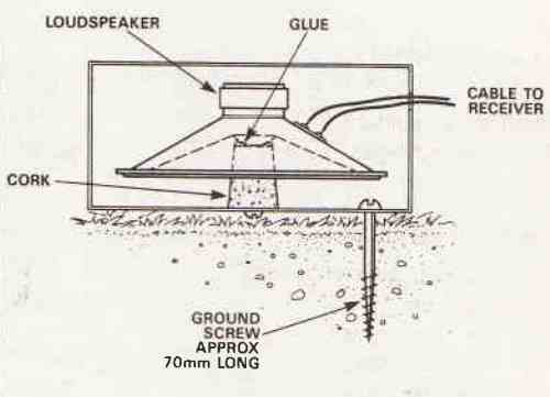
The structure of the sensor is seen in the Figure above.
The loudspeaker is in fact lying on top of the cork, and vibration from the ground will be transmitted to the cone via the 70 mm long metric 5 screw.
The trickiest portion of the task is finally over.
Circuit Description

The footsteps detector electronics are simple, as you'll see. The sensor is situated someplace in the garden's rear, and a section of cable C carries its output to amplifier A1 (IC1).
A1 drives a basic diode detector with a fixed gain of 100, and the output of this amplifier passes to amplifier A2 (IC2) , whose gain may be adjusted from 10 to 100 to give sensitivity control.
The latch built around the IC 555 (IC3) swings over and turns on an alarm or a light whenever the output of A2 temporarily surpasses a certain threshold, possibly as a result of an intruder jumping over the garden wall.
How to Construct
The connecting wire to the detector circuit must be screened. The sensor has previously been detailed in great depth. It will do to use a 75 ohm TV cable.
The prototype utilized regular audio wire with screens.
The layout is not important because the circuit is relatively tiny and made on veroboard because the frequencies involved are quite low.

Due to the AC coupled nature of the circuit and the usage of very moderate gains, stabilized power sources are not necessary.
The circuit consumes 4mA from each rail, thus as long as it is turned off when not in use, the two batteries should have enough life.
Setting up
To prevent a strong wind from setting off the sensor box, it is advised that you place a block or small bag of sand on top of it.
The monitor point should become negative to the supply rail voltage if a foot is stomped on the ground around 7 meters from the sensor.
This can be verified using a multimeter attached to the monitor point with the sensitivity setting set to maximum.
However, the LED will often turn on with just a very slight meter deviation.
This is because even while the lC2 output will briefly drop to the negative rail in response to the vibrations, which are coming in at about 10Hz, a meter won't react in less than a nanosecond.
The alarm's sensitivity slider should be set such that it doesn't sound when nearby ambient noise is present.
Sadly, there are certain locations where this footsteps detector circuit cannot be utilized at all, such as close proximity to a large thoroughfare with heavy traffic or a mining or quarrying sector where there are frequently explosive events.


Need Help? Please Leave a Comment! We value your input—Kindly keep it relevant to the above topic!