The shop shutter guard circuit discussed here guards your shop when its shutter is closed i.e., at night if an intruder tries to break the shutter, the piezo senses the vibration and the relay is fired to which a 230 volt bulb can be connected which makes the intruder think that someone’s inside.....but he doesn’t know he’s fooled by you!
You can also use this circuit for various applications like shock sensor or you can install it in your home to sense the door knock and buzzer rings( if buzzer is connected to circuit ) . It can also be used for automobile safeguard purpose. . .
CIRCUIT DESCRIPTION:
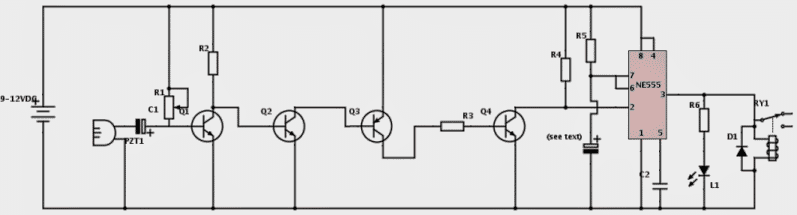
The circuit uses a piezo electric sensor to detect the vibrations. Usually piezos produce a voltage from few millivolts to 1 volt.
However, this voltage cannot have any use for our purpose. It have to be further amplified. So the four transistors are used here to amplify this voltage.
The amplified signal is fed to the pin2 of IC555 as trigger input. It in turn makes the output of the IC i.e., pin 3 of IC and this fires the relay and the buzzer(optional).
The output of the IC remains high for a preset time and after that time period, the output goes low and the relay and buzzer are turned off.
This time period can be varied by reducing or increasing the value of capacitor that is at pin6,7 and negative pole of DC source.
A 220uf (micro farads) capacitor can be used here. Its value may be varied to get desired timing interval.
The sensitivity of the circuit can be adjusted using the 2M preset. Take caution while soldering piezo as it is sensitive.
The shop shutter guard circuit works on any voltage from 6-12v but don’t forget to use the relay that matches with the voltage rating.
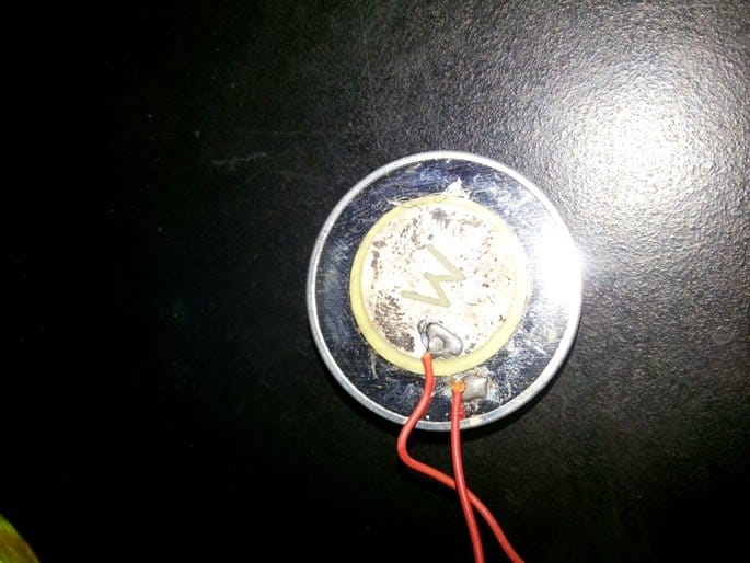
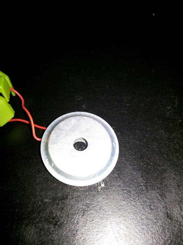
PLEASE REFER THE DIAGRAM OF PIEZO ELECTRIC SENSOR AND CONNECT THE MIDDLE WIRE OF PIEZO TO C1’s NEGATIVE AND OTHER WIRE OF PIEZO TO DC SOURCE NEGATIVE.
FIXING INSTRUCTIONS:
You can use a 0-12v transformer to power this up or in case of automobiles, connect this to the battery directly using a SWITCH to switch the circuit on and off.
And connect the car/bike’s horn to battery using relay contacts as a switch.
When someone moves the bike or tries to steal petrol or something from a bike, it senses the vibration and gives continuous horn for a predetermined fixed time, as set by the values of R5 and the series electrolytic capacitor.
You may use a buzzer instead if you don’t want to connect it to horn.
If you are using this for a shop shutter, you may connect relay contacts to a 230VAC bulb and fix the bulb outside the shutter.
You can assemble the circuit and enclose it in a plastic casing with holes for the sensor and power supply wires to reach the circuit.
Circuit Diagram
Written and Submitted by: SS kopparthy
PARTS LIST:
- IC-NE555,
- R1- 2meg preset,
- R2- 10K,
- R3- 1K,
- R4- 10K,
- R5- 1Meg,
- R6- 470ohms,
- C1- 2.2uf, 35v,
- C2- 0.1uf,
- Q1, Q2, Q4- 2N4401,
- Q3- 2N4403,
- L1- red led,
- PZT1- piezo electric sensor,
- D1- 1N4148,
- Relay- (as per voltage of power supply),
- Power supply- 9v-12v.


Questions & Answers
I would definately try this one…….I am back …..my exams are over……and I am currently working on PIEZO ELECTRIC SENSOR…….a different kind of circuit…..when finished would forward u the same…..Please give me some time for the Led propeller…..would be sending u soon……
sure Ajay, we'll wait for the updates.
Hello Sir!
How are you Sir? I'm back. After many attepmts contemplating on what kind of alarm is really suitable for my precious motorcycle, now I finally came up with what I think to be almost perfectly the one I want. It is the one you featured here, the SHOP SHUTTER GUARD CIRCUIT. I tried assembling it on breadboard and I was amazed and satisfied with the result. Even a single clap could trigger the circuit. I just replaced the 100uF capacitor with a much lower value to decrease the ON time.
But Sir, I still have a very minor question/problem. Here's the scenario. I used the relay to activate the bike's horn. I set the circuit to the sensitivity that I prefer. A single slight tap to the bike would trigger it. Very good indeed! But then the problem arises. Since the piezo sensor is attached to the frame/chassis of the motorcycle, and it activates the horn for alarm sound, the sounding horn continuously triggers the circuit and going on in loops. Because the piezo sensor gets triggered again by the horn sound. My question Sir, is there a way to make the circuit activates for a predetermined time only? And immediately resets to standby status after the horn stops. In that way, another vibration/intrusion can be sensed again.
Thank you so much Sir. I very much appreciate your unparalleled knowledge and patience with me. I will be posting the project when finished.
I am good Bugoy, thanks!
you can rectify the issue by connecting a capacitor between the collector of Q4 and the junction of R4 and IC pin#2, the value of the cap can be anything between 0.1uF to 1uF
also make sure to connect a resistor from the collector of Q4 to the positive supply…the value of this resistor can be 1M
Hello Sir!
Wow that was a quick and easy modification. Will try it now Sir. I hope it would solve the issue. Thank you so much Sir. I will update you ASAP. Take care.
you are welcome Bugoy…wish you all the best
Hello Sir!
I just tried it now, something is wrong. Sometimes it works, sometimes it does not. I tried 0.1uF, 0.2uF, 0.47uF, 1uF. Why is that Sir?
Hello Bugoy, please remove the 1M resistor which I suggested from the collector of Q4 to positive. and check….
What I did Sir is, I taped the piezo face down on the table and put a small motor in the output of the 555. So that the motor will vibrate the table surface every time it triggers. It works sometimes but most of the time it does not. It does not trigger even if I tap the piezo sensor.
you must give some time to the capacitor which you connected at the collector of Q4 to discharge, because as per your requirement the circuit must not respond to rapid triggering….therefore if you tap consistently, if won't respond after this modification….also you can try increasing the value of of the 555 pin6/7 capacitor for acquiring longer activation of the load…
Sir, can I attach two piezo sensor in parallel? So i could put one in front and another at the back of the bike's frame/chassis?
yes it can be done!
Hello Sir!
I just got home. If I use an electrolytic cap, what would be the polarity? I found out last night that a ceramic cap will not work. Also, is there a way that can be done such that if power is applied to the circuit, it will not go to ON state initially? What I want is, when power is applied, it should be in the OFF state rather than ON state. Because it is kind of annoying if the bike's horn sounds every time I flip the switch ON for the alarm.
Thank you Sir. I will be waiting for your response. For the meantime, I will prepare the breadboard on the table now.
Hello Bugoy, it does not matter whether it's a polar or non-polar, both will work equally well, but it's important that Q4 conducts properly otherwise the IC pin#2 may not respond correctly through a low value capacitor.
Using a higher value cap might ensure a quick triggering than a low value capacitor, so it can be tried.
Good Morning Sir!
How are you? I tried again the circuit on breadboard this morning. It does not function again Sir. But if I remove the capacitor modification and bring back to original circuit it works Sir.
God morning bugoy, it has to function.
separate the stages and confirm them individually…disconnect the capacitor from the Q4 collector and manually connect it to ground and see how the 555 outputs responds and for how long it keeps the output stays ON….this will confirm the working of the 555 monostable.
next, take a LED with a 1K resistor and connect across Q4 collector and positive….tap the piezo and check the LED response…it should light up brightly with each tap on the piezo.
once this is also confirmed, connect the stages for getting the final expected results.
a resistor 1M should be connected from Q4 to positive to ensure discharging of the capacitor otherwise the circuit will not respond repeatedly.
alternatively you can try a different approach.
keep the circuit as shown in the diagram…….connect a transistor BC547 with its collector connected with Q4 base, emitter to ground and base to pin#3 of IC 555 via a 100k resistor. feedback loop will prevent the circuit from latching to its own alarm sound
Hello Sir!
How are you? Been raining here all day. Sir, is there a way that can be done such that if power is applied to the circuit, it will not go to ON state initially? What I want is, when power is applied, it should be in the OFF state rather than ON state. Because it is kind of annoying if the bike's horn sounds every time I flip the switch ON for the alarm.
Thank you Sir.
to rectify this you can connect the pin#4 of the IC with the positive through a 10k resistor, and also connect a capacitor from pin#4 to ground…a 100uF will do
Wow! you are really a guru in your field of expertise Sir. Will surely try it now. I am really excited. By the way Sir, if I use a polarized cap using your previous suggestion, where would its leads go? Positive and negative? Q4 collector? 555 pin#2? My things are ready now. Just waiting for your response. Thank you Sir.
It's my pleasure Bugoy! for a polarized cap the negative lead will go to the collector of Q4
Hello Sir!
The 10k resistor and 100uF cap on pin4 did not work Sir. The circuit still initially turns ON upon switching ON.
Hello Bugoy, I think there's something wrong with your 555 circuit, it's not responding to any modification.
disconnect the 10K from positive and connect it to ground…remove the 100uF capacitor and now check.
this should completely disable the 555 output…if still the output sounds would indicate a faulty 555 IC.
if it gets disabled then you can be sure that the 555 is OK, in that case you can reconnect the resistor with the positive but change the 10k with a 100K and also place the 100uF cap back with pin4 and ground…..now you can check the switch ON response.
Hello Sir!
Good afternoon. I tried all your suggestions and found out several things. I put 1M resistor across Q4 collector and positive. A non-polarized capacitor (ceramic/mylar) dont work. But an electrolytic capacitor did. However, the polarity is the reverse. If i connect the negative lead of the cap to Q4 collector and positive lead to Q4/pin2 junction, it does not work. But if I reverse the cap (positive to Q4 and negative to Q4/pin2 junction), it did work. So far so good. Now will try to connect a buzzer if it serves its intended function and purpose. By the way Sir, I used a 100uF cap on Q4-R4/pin2 junction and 2uF on pin6/7 and negative. Will update you Sir.
Please see below set-up and video Sir:
i1284.photobucket.com/albums/a561/butchmillo/555_zpss2w69ve6.jpg
i1284.photobucket.com/albums/a561/butchmillo/piezo_zpsa1c7g9ng.jpg
vid1284.photobucket.com/albums/a561/butchmillo/2015-07-10-027_mobile720p_clipchamp.com_zpsb069wzm6.mp4
I am glad it's working for you presently Bugoy, but technically it's incorrect….the negative of the cap must connect with the Q4 collector and the positive lead with R4/pin6/2.
thanks for updating …keep up the good work.
a non-polar will also work….I am saying these just to make sure that readers may not learn the incorrect facts.
In your video the buzzer is not connected, I thought the capacitor was added to prevent the looping effect due to the buzzer sound vibrations…
The video does not show this crucial test result
Hello Sir!
I'm still working on it Sir. I have not connected the buzzer yet because it is too noisy and it is already evening here Sir. But I tried muffling it with my finger and testing the circuit, and it works Sir. Regarding the instant ON during power up, i am trying to experiment on different values of resistor and capacitor Sir. But in the end I used the 10K and 100uF as you previously mentioned. I Found out something puzzling. It works the first time I connected the RC network for PIN4. But succeeding ON and OFF will fail. Then when I disconnect the 10K resistor and re-plug it again on the breadboard, it works again, not turning ON when powered up. Another thing I found out is that if I waited long enough for power to be disconnected, and reconnect it again, it will work Sir. Maybe 10-15 seconds of disconnected power before the RC network of pin4 will be operational again.
Please enlighten me Sir. Thank you.
Hello Bugoy, connect a 100k resistor in parallel with the 100uF, this will allow discharging of the capacitor as soon as power is switched OFF. Presently it's not working quickly because the 100uF capacitor is not getting enough time to get discharged and return to its original state….adding a parallel 100k resistor will rectify the issue.
Hello Sir!
Good morning. I really did not proceed with the buzzer test last night because it might disturb anybody of its loud noise. I can do it today Sir. I am now preparing my demonstration to you. For the meantime, may I ask what do you mean by R4/PIN6/2? It was in your previous message. As far as the schematic is concern, PIN2 is not connected in any way to PIN6/7. Please clarify. Thank you.
Bugoy, it was a mistake from me…it should have been R4/pin2….and not R4/pin6/2
Hello Sir!
Can I just use 47uF and 10k resistor in parallel? Because the 100k/100uF still is not short enough for a power on succession. The 100k/100uF takes about 6-8 seconds to discharge. while the 10k/47uF only takes 2 seconds to discharge. Can it be done Sir? Any harmful effect on the circuit if I lower that values? Thank you.
Hello bugoy, yes that will do, no issues….I have been suggesting arbitrarily selected values and therefore it might not be accurate.
Also Sir, can I use 10k on Q4 collector to positive instead of the 1Meg resistor? That is because if I do 3 consecutive taps, the circuit will stop working. Maybe the 100uF across Q4 and PIN2 is not discharging fast enough. I tried replacing the 1Meg with 10k and it worked well Sir. Or could I just put a resistor in parallel just like in the RC network of PIN4? I am working on this the whole day Sir. But I can sense that we are going to solve this Sir. Just a little more tweaking.
yes 10k will do…I purposely suggested 1M so that the alarm switches OFF for sometime and under no condition responds to quick and random sound vibrations.
Thank you Sir…
Could you please look into these two options Sir? Which is better Sir? I have tried them both just now. Which is safer and better Sir? Both works almost the same Sir. I cannot tell the difference. Maybe you could better spot a more efficient and safer set-up Sir. Thank you.
i1284.photobucket.com/albums/a561/butchmillo/option%201_zpsotfxgx8a.jpg
i1284.photobucket.com/albums/a561/butchmillo/option%202_zpsr5ib4ufr.jpg
Hello Bugoy,
The following one looks more appropriate:
i1284.photobucket.com/albums/a561/butchmillo/option%201_zpsotfxgx8a.jpg
Hello Sir!
Thank you for your insight. I am making now on breadboard and will show you a video. Please stand by. I will now also design the pcb pattern for this. Hopefully by tomorrow I can have it laser printed so it would be easier for me to etch. I will post more pictures once I did something on the final design.
That's lovely Bugoy, I am glad to know this.
Here Sir…
The first video is the vibration loop solved. I showed in the video that if I remove the first modification (10k/100uF), the circuit will re-trigger and looping occurs due to the vibration/sound of the buzzer. But when I re-install the mod, it solved the problem. Thank you Sir. And by the way, you were right, the negative of the capacitor should go into Q4 collector and its positive will go into R4/PIN2 junction. I had it working already.
The second video shows that I can power up the circuit without initially triggering the 555 circuit. Thank you so much Sir. My problem now is a housing or a small box for it. There are no small project boxes here in our local electronics store. The smallest that they have is 10cmx6cmx3cm. That is way too big for this small project. Those enclosure are the ones I used for my laser tripwire alarm. It was a good project by the way because there is a reset button in case you want to silence the alarm sound.
vid1284.photobucket.com/albums/a561/butchmillo/2015-07-12-049_zpsgpdz3gl4.mp4
vid1284.photobucket.com/albums/a561/butchmillo/2015-07-12-050_zpsrhuvlire.mp4
Thanks Bugoy for all the detailed update, I am sure the folks will be enjoying this a lot.
I'll check out the videos soon…and let know if there's anything which might a correction.
However there's one drawback to this concept, it could trigger and cause spurious alarms by any external loud sound..like a bursting cracker or anything similar.
Hello Sir!
Good morning. Yes, I am aware of that sensitivity of the circuit. It can even detect a mild clap 10 feet away. I will just set the sensitivity to a moderate one. Also, I will only be using it during night time. Before I sleep and when everything is quiet and calm. As we know, burglars and thieves attack most of the time during the night. By the way Sir, can I include a capacitor across positive and negative? as a filter? What value is appropriate? Thank you.
Hello Bugoy, capacitors can be positioned across the supply rails, the value is not so critical, you can use a 100uF/25V and a 0.1uF, both in parallel
But You were right Sir about the drawback. I will just see during actual testing when I finish the project. I will let you know. Thank you very much…
Hello Sir!
Good morning. I got a problem. But not with the circuit. After sitting for 4 days in the garage, my bike got a low battery. It became 7 volts. It's been raining here Sir Since last week due to the two typhoons that hit us as well as the monsoon rains. So I am not able to use my bike for quite some time. I do not have any charger around. 🙁
OK no problem Bugoy, confirm the circuit after things become completely normal, and favorable for the testing.
Hello Sir!
Good morning. Still raining heavily here. May I ask if you have the simplest yet the best motorcycle battery charger circuit? Something easy to build, cheap but effective. Thank you Sir. I am planning to make one since the rainy season here is still a long way to go.
Hello Bugoy, it's a rainy season here too in Mumbai, but unfortunately it's not raining sufficiently here.
you can try the following circuit for charging your battery, just replace the input source with a 24V 2amp DC,, and adjust the 10k pot to produce around 14V at the output…..connect this to the battery terminals and wait until the ammeter needle falls to zero mark, which would indicate "battery fully charged"
sorry…here's the link:
https://www.homemade-circuits.com/2012/04/how-to-make-solar-battery-charger.html
Hello Sir!
How are you? Please look again into the schematic featured here. I think Q3 is wired in reverse, I tried doing what is mentioned here and it did not work Sir. The emitter of Q3 should be connected to positive, not to Q4. The collector of Q3 is the one to be connected to Q4. Since it is a PNP. Please clarify. Thank you.
Hello Bugoy, you are correct Q3 is wrongly connected, the emitter must go to the positive rail, I hope you have done it correctly in your design, actually you should have indicated this at the start of our discussion, right?
Hello Sir!
I have some last questions Sir. How can I connect my horn interrupter circuit to the shock sensor circuit Sir? Below are the two circuits Sir. Thank you,
i1284.photobucket.com/albums/a561/butchmillo/interruper_zpstuvumvd6.jpg
i1284.photobucket.com/albums/a561/butchmillo/option%201_zpsotfxgx8a.jpg
where is the horn interrupter design? the first one looks like a simple 555 astable.
Sir…
The first figure is the horn interrupter. Is it a wrong circuit Sir? Please guide me Thank you.
Bugoy, If the connected horn is a self-sounding horn then the circuit is OK, you just have to to tweak the ON/oFF cycles of the 555 in order to adjust the interruption delays.
in that case you just have to integrate the pin4 of the interrupter with pin3 of the above circuit's IC 555.
Yes Sir, it is self-sounding horn/buzzer. Will do it now Sir. No resistor anymore to connect PIN3 of sensor and PIN4 of interrupter Sir? How about pin8 of interrupter circuit? Below is my understanding of what you have said Sir. I also corrected the orientation of Q3 in the diagram Sir.
i1284.photobucket.com/albums/a561/butchmillo/final_zps1yxet4hx.jpg
that is correct Bugoy…you can finalize it. Pin8 will stay connected with the positive line….I hope the horn is not rated to consume more than 100mA…otherwise the IC might start heating up
…if possible connect the pin4 through a 3V zener diode (cathode to pin3, anode to pin4) this will prevent any leakage voltage at pin3 from causing false alarms.
Good morning Sir…
Oh will do that zener diode mod Sir. Can you suggest any commonly available 3V zener Sir? Well, I still need to modify it a little Sir. Maybe I will just put a switching transistor on pin3 of interrupter to drive a relay for the horn. just to be safe. The horn/buzzer will surely consume more than 100mA. Is the diagram below already correct Sir? Please advice me on component values. especially the base resistor of the transistor. Thank you. Will be waiting for your response before I go to the electronics store.
i1284.photobucket.com/albums/a561/butchmillo/final_zps7nucdqca.jpg
Good morning Bugoy, I do not know the specific numbers, you can ask the shopkeeper to give a 3 or 4V zener…. that will do.
the diagram looks OK to me.
by the way the relay can be directly connected across pin3 to ground (with a diode)
Hello Sir!
Good afternoon. I just came home. Got the last pieces of parts needed, like 3v zener, terminal block, capacitors. Unfortunately Sir, the 3v zener did not work. The circuit keeps on activating. Does not stop triggering. I tried using 1N4148 and it works. Will that do Sir in replacement for the 3v zener? Thank you. I am now heating the flat iron for pcb toner transfer.
Hello Sir!
Just an update. Below is the etched pcb that I finished just now. Dinner time already, come let's eat Sir. Will drill the holes later.
i1284.photobucket.com/albums/a561/butchmillo/2015-07-16-070_1_zpsdqha01b9.jpg
Hello Bugoy, diode is not recommended, because the pin4 should be able to conduct both ways through pin3 to remain stable….a diode will not allow this, but anyway if it works for you, you can go ahead with it.
By the way a zener diode has to work, may be your zener is faulty.
The PCB layout looks great.
Hello Sir!
Good morning. Thank you for the compliment. Been working all day yesterday on the project. So far, so good. Below are some snapshots. Today I will be working on the piezo sensors. I will be using shielded wire. I made 3 ports in the pcb for the sensors in parallel. Thank you again Sir. I cant wait to field test it directly on the bike.
i1284.photobucket.com/albums/a561/butchmillo/2015-07-18-072_1_zps8tbn79m8.jpg
i1284.photobucket.com/albums/a561/butchmillo/2015-07-18-073_1_zpsr10aqyhq.jpg
i1284.photobucket.com/albums/a561/butchmillo/2015-07-18-074_1_zpsmcgtnf4b.jpg
i1284.photobucket.com/albums/a561/butchmillo/2015-07-18-075_1_zpssqwvyp1k.jpg
i1284.photobucket.com/albums/a561/butchmillo/2015-07-18-076_1_zps5ygmnz47.jpg
i1284.photobucket.com/albums/a561/butchmillo/2015-07-18-077_1_zpsejywkolf.jpg
Sir, regarding the motorcycle battery charger that I mentioned previously, do you have any circuit that requires 220v input? Because I do not have a power supply that can cater to 24V 2A DC. the power supply that I am using in my electronics hobby is just a variable wall adapter having 500mA capacity. My bike's battery is 3Ah Sir.
Here is what it looks like Sir:
i1284.photobucket.com/albums/a561/butchmillo/2015-07-18-078_zpseiwt7rgw.jpg
i1284.photobucket.com/albums/a561/butchmillo/2015-07-18-079_zpsdcxkaexy.jpg
i1284.photobucket.com/albums/a561/butchmillo/2015-07-18-080_zpsjiomgucg.jpg
That's very neatly done Bugoy, the pictures look great, has a commercial look, I appreciate it a lot.
Sir…
I discovered something just now. Since the piezo sensor's negative side is directly connected to the circuit's negative supply, which is connected to the bike's battery negative and chassis/frame, it wont work if the piezo sensor is placed on any metal part of the bike.
Bugoy, this project is not an RF or capacitive based project, it's a straightforward amplifier circuit, so I don't here the negative or the ground line should have any kind of impact on the circuit's behavior….in fact amplifiers love large negative grounds for suppressing humming and stray disturbances.
By the way. would you be interested to become a paid contributor to my site….so far the amount of content and images that you have contributed, this could have otherwise easily fetched you more than $100 from me….
Check it proper;y, the issue could eb somewhere else.
Hello Sir!
That would be great. Since I do not have work as of now. I would very much appreciate it. Just let me know what else can I do for you. Regarding the slight trouble that |I encountered, it still works if the piezo sensor negative is touched to the supply negative. The relay only clicks faster than usual. And sometimes does not trigger. I will send you a video demo of what I am referring to. Thank you so much again Sir.
Any update on an easy-to-build but reliable motorcycle battery charger that I can make? That would require 220v input rather than 24v 2A dc? Thank you so much Sir.
Hello Bugoy, you can send me any researched article for publishing to my site (which is not yet posted in my site), along with a diagram, all these should be done with your own understanding and knowledge, not copied from any other site.
You can take the help from other online sources but make sure that you rephrase it sufficiently such that it looks original and a genuine contribution from you.
Making and testing it practically is absolutely NOT required, it's a secondary thing.
For more info you can contact me at: hitman2008 @ live.in
…you can use the following circuit for charging your battery:
https://www.homemade-circuits.com/2012/04/how-to-make-solar-battery-charger.html
Hello Sir!
I will e-mail you asap. By the way, is there any other best battery charger circuit that uses mains input? Because I do not have a dc power supply for a dc input charger Sir. Thank you.
Thanks Bugoy,
I have replied to your email.
Actually you can simply use a 14V DC 1amp power supply to charge the battery and monitor the battery voltage for about 8 hours and then remove it once it reaches the 14V (fully charged) mark
Hello Sir…
As I have said in my previous replies, I do not have a DC power supply that can deliver 14V 1A Sir. The only power supply that I have and use in my electronic projects is a common variable dc wall adapter maximum of 12V 500mA Sir. I sent a picture of my 12V adapter Sir.
i1284.photobucket.com/albums/a561/butchmillo/2015-07-18-078_zpseiwt7rgw.jpg
i1284.photobucket.com/albums/a561/butchmillo/2015-07-18-079_zpsdcxkaexy.jpg
i1284.photobucket.com/albums/a561/butchmillo/2015-07-18-080_zpsjiomgucg.jpg
Hello Bugoy,
what's the AH rating of the battery?
The charging input current should be not less than 1/10th of the battery AH otherwise it won't charge properly and might take a lot of time to get fully charged.
Hello Sir!
Good morning. It is 3AH lead acid battery Sir. Please refer to its picture below. Thank you so much Sir. I am still working on the piezo sensors Sir. Still designing how to make them. I am thinking of looking for a circular disc type enclosure that is small and thin enough to house the piezo element.
i1284.photobucket.com/albums/a561/butchmillo/51cE0rzledL._SY300__zps8r4ipxem.jpg
Hello Bugoy,
OK then the 500mA, 14V adapter will do the job nicely….you can use it for charging the battery, but be sure to remove it after about 10 hours of continuous charging.
Hello Sir…
Ok sir, will try it tomorrow. By the way Sir, Since I have a multimeter, how can I use it to monitor the charging process? Amp reading? voltage reading? If so, how? At what voltage will I stop the charging? Thank you.
Hello Bugoy, you can choose the voltage monitoring option and check the voltage of the battery after every one hour, as soon as you see the voltage reaching the 14V mark, you can assume it to be charged at a reasonably good level…and remove it.
initially, when you connect the adapter supply to the battery, you'll find the supply voltage dropping to the battery's discharge level, that is to may be 10.5v or whatever may be the discharge level of the battery, and this will gradually rise while the battery gets charged.
Hello Sir!
Thank you so much. I will surely do it Sir. I will update you asap.
By the way Sir, my bike's battery drops to 8.24v this morning Sir.
no problem just keep the adapter connected, however if there's no response (voltage build up) even after an hour or so, then you can assume the battery to be dead and it might require high current charger for reviving it.. a 2 amp adapter can be tried…
Hello Sir!
I still have not finished the piezo sensor project because I cannot think or find a good housing for the piezo element. I will upload a video now showing the reaction of the relay/circuit if I touch the piezo body to negative rail/supply.
But overall performance of our piezo sensor project is quite excellent Sir. Thank you very much for all your help and support. I am looking forward to putting it in my bike any time soon.
It's my pleasure Bugoy, keep up the good work!