Generating electricity from piezo could be as easy as making a flick with your finger..... curious to know how? I have explained more about this amazing device called piezo, which can be used for generating music as well as electricity.
How Piezo Responds to Force and Electricity
Piezo material is a crystalline substance which has the property of generating electricity when its crystalline structure is subjected to a certain mechanical stress level.
Conversely when the same crystalline structure is subjected to an electric current it exhibits an equivalent level of deformation which in turn causes a sound to be generated.
That's exactly why piezo elements are used in buzzers for generating sound by applying an pulsating voltage across it.
Therefore we can conclude that the discussed property of piezo material is flexible and reversible, meaning it allows both, generation of electricity when deformed, and generation of sound when electrified.
Having said this, care must be observed not to over limit the stress level on a piezo while attempting to generate electricity from it since the deformation limit of a piezo element is
extremely small, exceeding which could result in breakage or permanent
damage of the element.
How to Generate Electricity from Piezo
For experimenting the generation of electricity from a piezo, the easiest way to access a piezo material is to procure the standard 27mm piezo element which are normally used in piezo buzzer circuits.
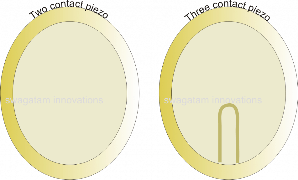
The picture below depicts a couple 27mm piezo elements which may be readily available in most electronic spare part stores.
The right side pic shows a 2-pin piezo element, while the other one represents a 3-wire, any of these will work for the experiment.
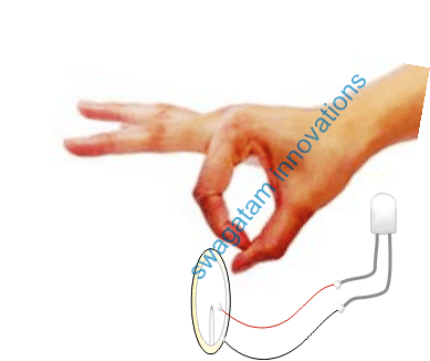
Once the piezo is procured, solder a couple of wires to it, connect a 20mA white LED across the other end of the piezo.
As soon as the above assembly is built, you can make the LED illuminate brightly momentarily by flicking the edge of the piezo with your finger.
Each time you strike the piezo with your finger, you can find the LED illuminating brightly during that instant.
And somehow if the striking is sustained through some external means, would enable the LED to illuminate rapidly, or even continuously if a capacitor is connected across its leads.
If the output across the piezo wires is measured, you would be surprised to see the voltage to be as high as upto 3V depending on how hard the striking was.
While conducting the above experiment make sure the piezo is pinched tightly from opposite edge with your other hand fingers, do not clamp through any mechanical tool as that could crack the piezo causing permanent damage to the element
Applications Hints:
Please also see how to charge battery with a piezo mat circuit
Illuminated Carom Board Using piezo Lit LEDs
The above explained concept of generating electricity from piezo transducer and illuminating an LED could be implemented in carom boards, for producing attractive LED illumination within the coins and also around the inner surfaces of the board rim.
SMD LEDs could be used for flush embedding them within the carom coins surface such that they do not affect the sliding effect of the coins.
The inner edges of the board could be also embedded with piezo/LED assemblies for generating the proposed piezo electric LED illumination.
Once this is done, each time the coins are struck or when coins hit the board edges the associated LEDs could be expected to light up brightly for that second producing interesting LED light show.
Using piezo electricity in Children Shoes.
The effect of piezo electricity could also be effectively used in children shoes, by suitably fixing the piezo, LED assembly beneath the heels of the shoes. This would enable the LeDs to light up brightly each time a step is taken by the child wearing these enhanced shoes.
Many more such innovative ideas could be implemented by using the proposed concept of generating electricity from a piezo buzzer element, if you think you have even more interesting ideas do let us know about it through your comments.


Questions & Answers
Hello,
I am a meducal researcher, I want an enthustic engineer to join a project to protect harm from ultrasonic and emf.
The attached reading was found on Feb 2, 2025.
This is dangerous level. I repeatedly asked help but no one help.
I need to help myself to find out and remove it immediately.
The Canafian and many guidelines tell it is dangerous level. My ears are painful.
Guideline
canada.ca/en/health-canada/services/environmental-workplace-health/reports-publications/radiation/guidelines-safe-use-ultrasound-part-industrial-commercial-applications-safety-code-24.html#a4.2.1
Then a medical research to reassess the harmful sources in the environment or intentionally place it recklessly.
No one can place such source no matter what reason.
Can you reply the easiest way to communicate?
Thank you very much.
Cecilia
Hi, thanks for your interest in the subject, this commenting platform is the easiest way to communicate with me.
how and where can this peizo electricity generated can be saved
inside 2 or 3 capacitors, then these capacitors could be connected in series to raise the output and this boosted charge could be transferred into a Li-ion battery.
Good day!
Sir Swagatam,
Please help me to build a regulated power supply input 60 VAC, 60hz
output 50 VDC 2kw, low ripple none parasitic regulated output. this proposed power supply
is to be use as a back up power supply of my existing off grid 3kw solar installation.so that my battery will will not drain during daytime and save for the night time. the proposed regulated power supply 50volts will parallel to the Battery output with blocking diodes so that if during cloudy the harvest goes down then instead battery will help the regulated power supply will handle load soon the the output of battery lower down to 50volts.
Hi Antonio, 50V 2kV looks huge, presently I do not have any power supply circuit even close to this massive value…so I am sorry won't be able to help with this design
Sir meri ap se request ye hay k ap 1 led cube banana sikha dain please
LED tube or cube?? With how many LEDs, please specify this?