In this post I have explained a simple IC 555 set/reset application circuit for activating or deactivating a relay alternately.
Audio/Video Representation
Circuit Operation
This electronic set reset circuit is very simple, easy to implement and very useful.
It can provide you many applications options in cases where it may be necessary to toggle (switch on and off) any electrical or electronic device
Understanding the ON-OFF or set/reset operation of the timer switch 555
To operate the timer 555. In this popular integrated circuit there a relay is connected via a BJT with the intention of connecting or disconnecting of the device to be controlled.
Manual activation may be performed via two momentary push ON switches. One serves to activate the device under control and the other for deactivating the same.
When the circuit is operating, activation of switch 1 (SW1) enables the pin2 of 555 linked to 12 volts normally, pulling it to 0 volts such that the timer output (pin3) is activated, allowing voltage 12 volts here. Thus, high output activates the relay 555 through the transistor Q1 (which saturates)
For disabling the relay, simply switch 2 (SW2) is pressed.
This puts pin 6 of timer 555, at a high voltage temporarily. The output of 555 that is pin3 now gets a low voltage level at its output, deactivating the transistor in the course, and clearing of the relay.
Circuit Diagram
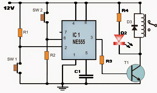
Note: In the explanation of the circuit, it is proposed to be fed with 12 volts, however it may work well even with a voltage range from 5-15 volts. One can use a 9 volt battery PP3, and thus have a much portable circuit.
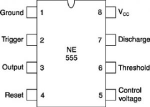
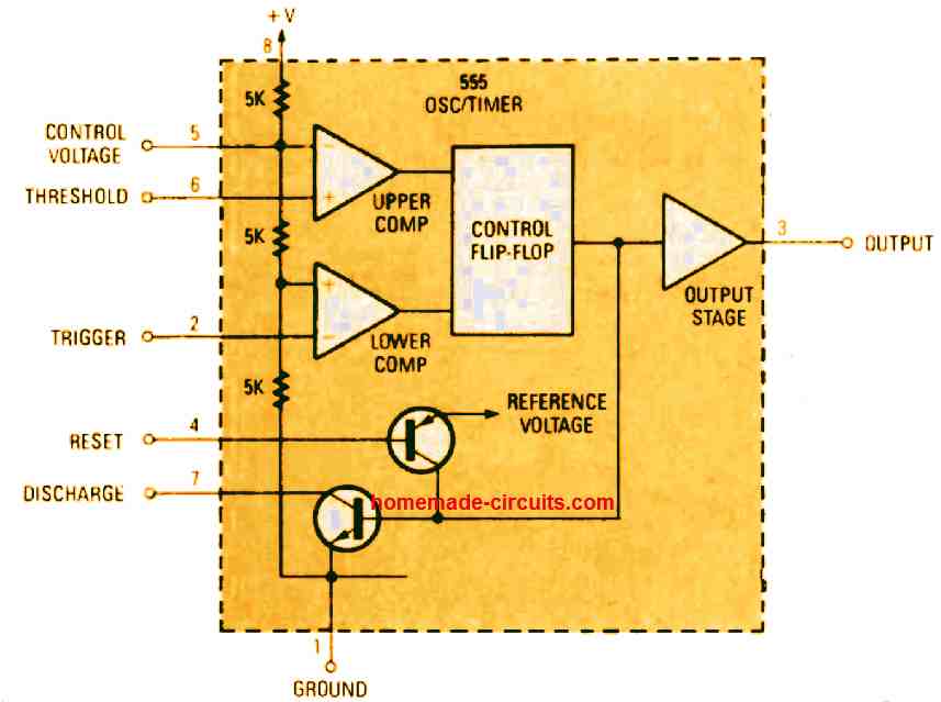
IC 555 pinout
List of circuit components for the above explained IC 555 set reset circuit
- Resistors: R1 = R2 = 3.3M, R3 = 10K, R4 = 1K
- Capacitors: C1 = 10nF
- Transistor: BC547
- Rectifier Diode: 1N4148 or equivalent
- Diode LED: 1 red
- Integrated circuit: NE555
- Relay: 1 with identical voltage to the supply voltage of the circuit
- Switches: 2 momentary or similar push ON contact. (SW1, SW2)
- Other: battery connectors (CN3), switches (CN1, CN2). View the latest chart.
By: Manisha Patel

Questions & Answers
Hi Swagatam, I was just wondering if I could ask you about a circuit that is based on the above circuit but has a different trigger requirement.
Regards
Geoff
Hi Geoff, you can feel free to ask it.
Thanks Swagatam,
The basis of what I am trying to achieve is I need to hold a solenoid active for around 10 seconds,the trigger is a high. I tried a 555 monostable and got the time with capacitor and resistor values, but trigger for this is a low so I ran pin 2 through a BC547 to switch the signal to ground and send pin 3 high. This worked a few times and now pin 3 stays high all the time , I think it may be fried. The output of pin 3 goes through a BC547 a 12 volt relay to the solenoid. The solenoid is 12V 1A,the relay coil 50mA and I have 10K resistors on the BC547's. Do you think I am on the right track or is there a better way.
The trigger voltage is 5 volts.
Regards
Geoff
Hi Geoff, you have done everything correct in your design.
Did you connect a diode across relay coil?
I cannot see anything wrong in your design, may be the IC itself is not a good quality one, you can try replacing the IC…or the BC547 could also be examined for the same.
Hi Swagatam, Thank you for the confirmation, yes I have a diode on the relay coil. You are right about the quality of the IC's they are the "dodgy 10 for a dollar ones", I shall invest is some decent ones.
Thank you
Regards
Geoff
you are welcome Geoff!!
I HAVE TWO QUESTIONS HERE: 1. WILL THE ON PUSH BUTTON BE HELD IN AS THE LOAD IS ON AND RELEASED AS THE RESET BUTTON IS PRESSED AS IN THE CASE CONTACTOR SELFHOLDING. 2. WILL ANY PUSH BUTTON BE USED IRRESPECTIVE OF CURRENT RATING.
You have to press the push button just momentarily for a second and then release to operate the relay ON or OFF, depending upon which push button was pressed.
Hello sir,
Is there any cmos ic can be uset for set reset circuit with low power consumption than NE555 , so that can be used with battery with long life. Pls if possible publish a post with circuit.
Thanks in advance
Hello Nitin, You can find many CMOS based circuits if you search it online, I presently do not have it in this website…however if reducing current consumption is your main requirement in that case you can also try a transistor based design, as discussed in the following example post
https://www.homemade-circuits.com/simple-gate-openclose-controller-circuit/
Si prolongo el sw1 y 2 con cable utp y utilizo 2 placas se genera un rebote y al apagarce una se enciende la otra porque puede ser??
Intente conectar condensadores a través de los terminales del interruptor y verifique si eso ayuda. Puede usar 0.22uF o cualquier condensador hasta 1uF.
I’m looking for a simple on off timing relay, turn switch on powers relay 10s on then shuts down for 10s then repeats again and again 12v coil. Or a 14 pin DPDT combined timer relay repeat. Or do you think it’s just a easy to bye it on ebay?
Jim
you can try the following circuit
use 100uF for the C
connect the relay directly across pin 3 and the ground line
Good day sir, please how can I make 555 timer for 5secs delay for power on and power off. Thanks
Adeyemi, please search “555 timer” in the search box, you will find many options
Hi Swagatam,
I am looking to build an oscillating circuit based on 555 timer/s.
I wish for the circuit to drive a relay on for a time, then off for a different amount of time,
I want to be able to vary the periods of on-time and off-time.
Example On for 10 sec then Off for 2 sec. the change the timing altogether
to say On for 5 seconds then Off for 20 seconds.
Is it possible to have this performance from 555 circuit.
Thanks for your thoughts,
Mal
Hi Mal, it may be possible to some extent. You can refer to the PWM based designs in the following article, and use one of them as per your suitability
https://www.homemade-circuits.com/ic-555-oscillator-alarm-and-siren-circuits/
Please how can I use this circuit as astable mode with 1 cycle without resetting it
Please read the following article, for all the details:
IC 555 Pinouts, Astable, Monostable, Bistable Circuits with Formulas Explored
Hi Swagatam. Two problems with this circuit. When power is first applied, the circuit switches ON. Also, the push buttons are working in reverse: Pressing SW1 turns it off and pressing SW2 turns it ON. This is not what you’ve stated in your article..
Hi Maurice, to ensure the circuit does not turn ON when power is first applied, you can try connecting a 1uF capacitor across the positive rail and the pin6 of the IC.
The SW1 will switch ON the output and SW2 switch OFF, because grounding pin 2 will always activate the output with a positive signal, the opposite can never happen, it is impossible.
Hi.
Can i destroy the 555 circuit if S1 is active for 1-2 days or more?
I plan to build a circuit to refill water as needed in a self-watering pot and replace S1 and S2 with magnetic switches that are affected by a magnetic float where S1 stands for maximum level and S2 for minimum level of water.
I would be grateful for an answer.
Regards.
Peter Lörne
Hi, The IC will not get destroyed even if the switches are held constantly pressed, alternately. You can use the circuit for your self watering pot application.
Hi. This projekt “Simple Set Reset Circuit using IC 555” is interesting.
Why do you use pin 6 insted of pin 4 the resetpin?
Regards
Peter Lörne
Hi, thank you. The set/reset functions are compatible with each other. One lifts the threshold above 2/3 supply, and the other brings it down below 1/3rd supply, therefore the two functions are better suited with each other in this application.
Thanks for your reply!
I will try this solution, so I will see if I get a better stability and durability.
I have had some problems with my self filling of water in a large pot that I wrote about in a previous post to you.
Has burned 2 chips with the other variant pin 2 and 4
You have to keep your fingers crossed for me that it works.
Regards
Peter
Thank you for your feedback!
Hi Swagatam!
I have now built the application on an expriment card and it works quite well except that it is very sensitive. As soon as I touch my finger on pin 2, pin 3 goes high and when I touch pin 6 pin 3 goes low.
Do you have a solution to make it less sensitive?
I want the circuit to just react to the swithes
Regards.
Peter
Hi, Peter, It is good to know your circuit is working. I think you can try connecting a 0.47uF capacitor right across the switch terminals and check if that helps to prevent the circuit from responding to direct touch.
I try that. ????
/Peter
sure, no problem!
It works ! 🙂
Now i am to build it on pcbcard and inpliment it in my grenhouse to the summer.
Thank you.
I hope you get a fine sommer.
Regards.
/Peter
That’s great Peter, all the best to you!
Hi Swagatam.
Would like to feedback to your circuit that I will use in the greenhouse for automatic water filling.
I want to extend it with a time monitoring of the relay.
The idea is that when the relay is switched on by sw1, you have a maximum of X minutes to sw2 does a reset, otherwise the monitoring closes the relay and remains closed until you restart the circuit.
This is to prevent flooding if there should be a fault on Sw2 which in my case is a magnetic switch (as I mentioned earlier) where Sw2 stands for max level of water.
Do you have any idea or solution to this problem?
Hope you understand what I mean.
Regards
Peter
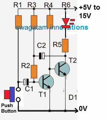
Hi Peter, I think the following modified IC 555 monostable circuit might do the job for you:
THe value of R1, C1 determines the maximum OFF time delay.
Thank you Swagatam !! 🙂
I try that.
I am very grateful for your help!
Regards
/Peter
You are welcome Peter!
INTERESTING, SO THIS CIRCUIT IS CAPABLE OF SELF HOLDING LIKE CONTACTOR AND PUSH BUTTON SWITCH NETWORK.
yes it is designed to latch and break alternately when the two buttons are toggled alternately.
Hello,
I have a car that doesn’t have an accessory position for listening to the car radio. This circuit looks like it’s almost right for this – sw1 to activate (i.e. listen to radio, ignition off) and sw2 (to turn off the radio manually and deactivate the circuit). The extra function needed is for turning on the ignition to disable it as well. I know enough to make a circuit like this, but not enough to modify/design it! I think the issue would be sending a momentary trigger triggered by the ignition switch. Are you able to help?
Hi, It can be perhaps simply done by connecting a BC547 transistor across SW1.
Collector to Pin#2
Emitter to Ground.
Base to ignition supply via a 100K resistor.
Also connect a 1uF/25V capacitor between base and emitter.