In this post I will show how to construct a RFID based attendance system, which can record attendance of 12 students / staffs for a given time window and this system can record up to 255 attendances per person.
What is RFID Attendance System
We don't need any introduction regarding the RFID based attendance system, it is being used in colleges, office, libraries to know how many times a person or how many number of people has come in and out at what time.
In this project we will be constructing a simplest RFID based attendance system which does not overcomplicate the project.
In this project we will be using RTC module, which is utilized for enabling and disabling the attendance system within a given time period, so that we can keep the late comers at bay.
The RFID module “RFID-RC522” which can do read and write operations on NXP based RFID tags. NXP is lead producer of RFID tags in the world and we can get them on online and offline stores easily.
A 16 x 2 LCD display is used, which is to showcase information such as time, date, number of attendance, etc.
And finally an Arduino board is utilized which is the brain of the project. You may choose any version of board.
Now let’s move on to schematic diagrams:
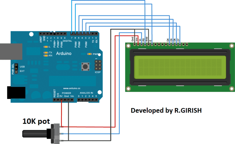
Arduino to LCD display connection:
Just connect the wiring as per the below diagram and use 10 kilo ohm potentiometer to adjust the contrast.
Arduino to RFID module connection:
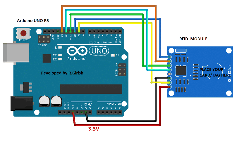
The RFID module must be powered by 3.3V and 5V can damage the on board components. The RFID-RC522 module works on SPI communication protocol while communicating with Arduino.
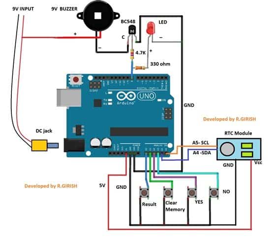
Rest of the circuit:
The Arduino can be powered from 9V wall adapter. There is a buzzer and LED to indicate that the card is detected. There are 4 buttons provided for viewing the attendance, clearing the memory and “yes” and “no” buttons.
That concludes the hardware part.
Please download the following library files:
Link1: github.com/PaulStoffregen/DS1307RTC
Link2: github.com/PaulStoffregen/Time
Link3: github.com/miguelbalboa/rfid.git
Now we have to set the correct time to RTC module to do this, follow the below steps with completed hardware setup.
- Open the Arduino IDE.
- Navigate to File> Examples> DS1307RTC> SetTime.
- Upload the code.
Once the code is uploaded to Arduino, open the serial monitor. Now the RTC is synchronized with the time of your computer.
Now you have to find UID or unique identification number of all 12 RFID cards/tags. To find UID, upload the below code and open the serial monitor.
Full Arduino Code
//-------------------------Updated Program cleaned & corrected------------------//

#include <LiquidCrystal.h>
#include <EEPROM.h>
#include <SPI.h>
#include <MFRC522.h>
#include <Wire.h>
#include <TimeLib.h>
#include <DS1307RTC.h>

#define SS_PIN 10
#define RST_PIN 9
#define LED 8

MFRC522 rfid(SS_PIN, RST_PIN);

// LCD pins
LiquidCrystal lcd(7, 6, 5, 4, 3, 2);

// Button pins
const int listBtn = A0;
const int clearBtn = A1;
const int yesBtn = A2;
const int noBtn = A3;

// Time window
int h  = 21;
int m  = 0;
int h1 = 21;
int m1 = 50;

boolean attendanceOpen = false;

// ---------------------------------------------------------------------------
// data structure (Clean, short, professional)
// ---------------------------------------------------------------------------

struct Student {
  const char* uid;
  const char* name;
  int eepromAddress;
};

Student students[] = {
  {"F6:97:ED:70", "Student1", 1},
  {"45:B8:AF:C0", "Student2", 2},
  {"15:9F:A5:C0", "Student3", 3},
  {"C5:E4:AD:C0", "Student4", 4},
  {"65:1D:AF:C0", "Student5", 5},
  {"45:8A:AF:C0", "Student6", 6},
  {"15:9F:A4:C0", "Student7", 7},
  {"55:CB:AF:C0", "Student8", 8},
  {"65:7D:AF:C0", "Student9", 9},
  {"05:2C:AA:04", "Student10", 10},
  {"55:7D:AA:04", "Student11", 11},
  {"BD:8A:16:0B", "Student12", 12}
};

const int totalStudents = sizeof(students) / sizeof(Student);

// ---------------------------------------------------------------------------

void setup() {
  Serial.begin(9600);
  lcd.begin(16, 2);

  SPI.begin();
  rfid.PCD_Init();

  pinMode(LED, OUTPUT);
  pinMode(listBtn, INPUT_PULLUP);
  pinMode(clearBtn, INPUT_PULLUP);
  pinMode(yesBtn, INPUT_PULLUP);
  pinMode(noBtn, INPUT_PULLUP);

  digitalWrite(LED, LOW);
}

// ---------------------------------------------------------------------------

void loop()
{
  handleButtons();
  showDateTime();

  updateAttendanceWindow();

  if (!rfid.PICC_IsNewCardPresent()) return;
  if (!rfid.PICC_ReadCardSerial()) return;

  String uid = readUID();
  processUID(uid);

  rfid.PICC_HaltA();
  rfid.PCD_StopCrypto1();
}

// ---------------------------------------------------------------------------

String readUID()
{
  String StrID = "";
  for (byte i = 0; i < 4; i++) {
    StrID += (rfid.uid.uidByte[i] < 0x10 ? "0" : "");
    StrID += String(rfid.uid.uidByte[i], HEX);
    if (i != 3) StrID += ":";
  }
  StrID.toUpperCase();
  return StrID;
}

// ---------------------------------------------------------------------------

void processUID(String uid)
{
  if (!attendanceOpen) {
    lcd.clear();
    lcd.print("Attendance");
    lcd.setCursor(0, 1);
    lcd.print("Closed");
    delay(1200);
    return;
  }

  for (int i = 0; i < totalStudents; i++)
  {
    if (uid == students[i].uid)
    {
      int count = EEPROM.read(students[i].eepromAddress);
      count++;

      if (count >= 256) {
        showMemoryFull();
        return;
      }

      EEPROM.write(students[i].eepromAddress, count);

      lcd.clear();
      lcd.print("Attendance OK");
      lcd.setCursor(0, 1);
      lcd.print(students[i].name);

      digitalWrite(LED, HIGH);
      delay(1000);
      digitalWrite(LED, LOW);
      return;
    }
  }

  // ❗ If no UID matched
  showUnknownCard();
}

// ---------------------------------------------------------------------------

void handleButtons()
{
  if (digitalRead(listBtn) == LOW) showAttendanceList();
  if (digitalRead(clearBtn) == LOW) clearMemoryPrompt();
}

// ---------------------------------------------------------------------------

void updateAttendanceWindow()
{
  tmElements_t tm;
  if (RTC.read(tm))
  {
    if (tm.Hour == h && tm.Minute == m)  attendanceOpen = true;
    if (tm.Hour == h1 && tm.Minute == m1) attendanceOpen = false;
  }
}

// ---------------------------------------------------------------------------

void showDateTime()
{
  tmElements_t tm;
  if (!RTC.read(tm)) return;

  lcd.clear();
  lcd.print("TIME:");
  lcd.print(tm.Hour);  lcd.print(":");
  lcd.print(tm.Minute);lcd.print(":");
  lcd.print(tm.Second);

  lcd.setCursor(0, 1);
  lcd.print("DATE:");
  lcd.print(tm.Day);   lcd.print("/");
  lcd.print(tm.Month); lcd.print("/");
  lcd.print(tmYearToCalendar(tm.Year));

  delay(1000);
}

// ---------------------------------------------------------------------------

void showAttendanceList()
{
  for (int i = 0; i < totalStudents; i++)
  {
    lcd.clear();
    lcd.print(students[i].name);
    lcd.print(":");
    lcd.print(EEPROM.read(students[i].eepromAddress));
    delay(1800);
  }
}

// ---------------------------------------------------------------------------

void clearMemoryPrompt()
{
  lcd.clear();
  lcd.print("Clear All Data?");
  lcd.setCursor(0, 1);
  lcd.print("Hold YES");

  delay(2000);

  if (digitalRead(yesBtn) == LOW)
  {
    for (int i = 1; i <= 12; i++)
      EEPROM.write(i, 0);

    lcd.clear();
    lcd.print("Data Cleared");
    delay(1200);
  }
}

// ---------------------------------------------------------------------------

void showUnknownCard()
{
  lcd.clear();
  lcd.print("Unknown RFID");
  lcd.setCursor(0, 1);
  lcd.print("Card!");

  for (int i = 0; i < 3; i++)
  {
    digitalWrite(LED, HIGH);
    delay(200);
    digitalWrite(LED, LOW);
    delay(200);
  }
}

// ---------------------------------------------------------------------------

void showMemoryFull()
{
  lcd.clear();
  lcd.print("Memory Full!");
  lcd.setCursor(0, 1);
  lcd.print("Clear EEPROM");

  for (int i = 0; i < 20; i++) {
    digitalWrite(LED, HIGH);
    delay(100);
    digitalWrite(LED, LOW);
    delay(100);
  }
}

//-------------------------New Program cleaned & corrected------------------//
How the Code Works
Above we build an RFID Attendance System using Arduino, MFRC522, DS1307 RTC, LiquidCrystal, and EEPROM. Now we will explain how to upload, how to change UIDs, how to test, and how to troubleshoot. Let us begin now.
Components Required
- We need these parts for the project.
- Arduino Uno or compatible board.
- MFRC522 RFID Reader Module.
- RFID Tags or Cards.
- 16x2 LCD with HD44780 controller.
- DS1307 RTC Module.
- Jumper Wires and Breadboard.
- A Status LED and four Buttons (List, Clear, Yes, No).
- Power Supply 5V.
- We suggest you have a USB cable for programming.
Wiring
We connect components exactly like this so the code runs correct.
Connect MFRC522: SS_PIN to Arduino D10, RST_PIN to D9, MOSI to D11, MISO to D12, SCK to D13, VCC to 3.3V, GND to GND.
Connect LCD: RS to D7, EN to D6, D4 to D5, D5 to D4, D6 to D3, D7 to D2.
Connect RTC: SDA to A4, SCL to A5, VCC to 5V, GND to GND.
Connect Buttons: List button to A0, Clear button to A1, Yes to A2, No to A3. Use INPUT_PULLUP or external pullups so that the buttons read LOW when pressed.
Connect LED to D8 with series resistor to GND.
Now check all wires and that there is common ground.
Code Overview
This makes code short, that is easy to change. We preserved the original attendance window logic so that attendance is allowed only in the configured time range.
The code reads RFID UID compares with list, then increments corresponding EEPROM address. If memory reaches 256 then code shows memory full message and asks to clear.
How To Configure UIDs And Names
Open the code in Arduino IDE. Locate the students[] array near top. You will see lines like:
{"F6:97:ED:70", "Student1", 1},
Change "Student1" to your student name or employee name exactly as you want it to appear on LCD. Do not change UID format. Keep colon separators and uppercase hex like F6:97:ED:70.
If then you want to add or remove students, update totalStudents and ensure EEPROM addresses are unique and not overlapping with other data. We used addresses 1 to 12 for convenience.
Setting Attendance Time Window
Inside code you will find variables h, m, h1, m1. These are the From and To times. For example h = 21, m = 0 means attendance opens at 21:00. h1 = 21, m1 = 50 means attendance closes at 21:50.
If then you want a different window, change those numbers. Remember times are in 24 hour format.
Upload And First Run
Let us upload code to Arduino. Connect Arduino to PC. In Arduino IDE select correct board and COM port. Click Upload.
After upload, open Serial Monitor at 9600 baud just to see debug lines if any. Place a known RFID card near the reader.
The LCD will show TIME and DATE if RTC is working. If then attendance is open the card will register and LCD will show "Attendance OK" and the Name. If then attendance is closed the LCD will show "Attendance Closed".
How To Read UID Alone
If you only want to get card UID to paste into students[] array, use the simple UID reader sketch that prints UID on Serial Monitor.
Scan card, then copy the hex string in format like F6:97:ED:70. Then paste it into students[] list. This is helpful when you enroll new cards.
Buttons Operation
List Button (A0): When then you press List it will cycle through all names with counts read from EEPROM.
This is for quick checking without PC.
Clear Button (A1): When then you press Clear it will prompt Hold YES to clear all EEPROM counts. Press
Yes (A2) long press to clear. No (A3) will cancel.
Yes/No Buttons use INPUT_PULLUP so pressing makes them LOW. Keep that in mind while wiring.
EEPROM Counters And Limitations
We store each attendance count in a single EEPROM byte per student. That means maximum count is 255. If then the count becomes 256 the code treats that as overflow and shows Memory Full.
If you expect counts greater than 255 then we must change code to use two EEPROM bytes per student and read/write 16 bit integers. We left original simple byte storage because it is easy and small.
Troubleshooting
RTC Shows Read Error Or RTC Stopped:
If RTC read fails, then check DS1307 wiring, battery on RTC, and that you installed RTClib or DS1307RTC library. Run the SetTime sketch first to set current date and time.
Card Not Recognized Even Though UID Is In List:
If card does not match then check UID string format and case. The code converts UID to uppercase and inserts colons. Make sure stored UIDs match exactly including colons.
Unknown RFID Always Shown:
This was original code bug. We fixed it by using proper AND checks. If you still see Unknown, then ensure your UID stored is correct and that no extra whitespace or invisible characters exist.
LED Or Buttons Not Working:
Check pin numbers, use Serial prints to debug, and confirm pinMode and wiring.
Improvements You Can Do
Use 16 Bit Counters In EEPROM: If you want higher counts then use two EEPROM addresses per student and combine low and high bytes to form 16 bit integer.
Use SD Card For Full Logs: If you want timestamped logs for each scan then add microSD module and append logs with date and time from RTC.
Web Or Serial Export: If you want to export to PC then implement Serial commands to dump EEPROM counts or integrate ESP8266/ESP32 to send over WiFi.
Auto Enrollment: If you want to add new cards on the fly, then implement a long-press enrollment mode that writes scanned UID and name to free slot.
Additional Notes:
Replace student1, student2 with any name you wish or leave it as it is.
You have to set the time from when to when the attendance system should be active, rest of the time the system won’t register the attendance when we scan RFID tag/card:
// ------ From -------- //
int h = 21; // Hrs
int m = 00; // Min
// ------- To ------- //
int h1 = 21; // Hrs
int m1 = 50; //Min
//-------------------------//
The upper part is starting time and the lower part is ending time. You have to enter time in hours from 0 to 23 and minutes from 00 to 59.
Author’s prototype:
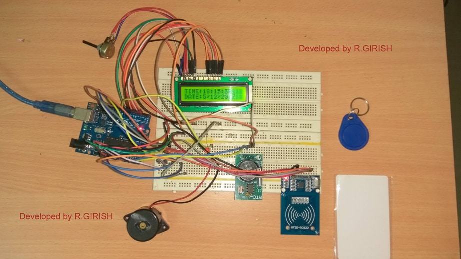
If you have any questions regarding this project, feel free to express in the comment section, you may receive a quick reply.




Questions & Answers
Thanks so much Abbey, Do you intend to have an adjustable timer circuit that would dispense the fragrance through some mechanism at given time intervals? please elaborate a bit so that I may get a clear idea of the device….
Kudos Swag, here is the idea. there are several of it in the open market. mine is manually fill into a manufacture container with spray gun, you press it it realeases. what I want to achieve is how possible to get a container which is more of plastic not sealed container like flit. a plastic type manually refill with a device to mounted on the mouth that can spray at an interver using battery. hope you got it
OK thanks, I have understood, possibly I’ll try to design it and publish the article in my website soon….
Nice project , I will be constructing the project, Is it possible to take it further to data logging where the attendance register data can latter stored and reviewed and or printed from the computer
Thanks for help
Thanks Rashaka,
We will think about it, and if possible post the modifications in the article.
WHAT ARE THE COMPONENTS OF THIS PROJECT
Can we also interface gsm module in this project , so that each time when rfid card is read then a message can be sent on a mobile no.?
Prabhat,
It may be possible, however customized designs will require a fee for the designing.
Where is the attendance data stored? Is it possible to view the attendance data?
I am sorry Angelo, I won’t be able to provide help regarding Arduino related circuits since it was written and compiled by another author.
Hi Angelo,
The attendance data is stored in EEPROM of Arduino and you can view on the LCD, to know more read the full project.
Regards
sir,
i constructed the above project by following the steps line by line as u mentioned,but at time of running it. the project is displaying only time and date its not accessing the RFID part please can u help what may be the solution??
Vijaya, I have forwarded the question to Mr. GR, he may reply you soon.
Hi Vijaya,
My best prediction is that you forget to place the timing.
// —— From ——– //
int h = 21; // Hrs
int m = 00; // Min
// ——- To ——- //
int h1 = 21; // Hrs
int m1 = 50; //Min
//————————-//
You have to enter the timing, otherwise the card will ignore if scaned out the set time.
You have to enter time in hours from 0 to 23 and minutes from 00 to 59.
While testing set the time from now to next 15 mins. After this particular span time all cards will be ignored.
Also change your UID and name as per the instruction, if you haven’t.
Regards
Did you check your RFID tag / RFID reader works properly?
If not click here and check whether your RFID reader can read “UID” code from your tag : https://www.homemade-circuits.com/make-this-rfid-circuit-using-arduino/
Regards
thank you ir now the project is working absolutely fine .bu i have some doubts regarding project.
1:the rtc module is setting time according to GMT , i need to set to the local time(+5hours:30minutes) how can i do that??
2:where is the stored data can be collected ? example: if i placed the tag and my attendance is registered n so does the others how can i get how many tags attendance is registered??
do we need to extend project for that to collect the whole data of absenties ,presenties and all??
Hi vijaya,
To get your local time, make sure that your PC is set to local time and upload the RTC time setting code, Instructions are given in this project.
The attendance data is stored in EEPROM of Arduino, press the button connected to “A0” you can see the attendance registered of all 12 students. All 4 buttons are mandatory for this circuit don’t skip.
No external project is need to collect attendance data.
Regards
Regards
Please help me for ”Attendance is close problem”.
sorry, I won’t be able to suggest much regarding Arduino circuits, since I am not good with it….