For multi-storey buildings where water tanks could be at considerable heights over building terraces, monitoring the levels automatically could become a major issue. RF remote control modules have become pretty cheap nowadays which could be effectively used for solving the inconvenience. I have explained how to make and install a wireless water level controller circuit for the same, requested by Mr. Sriram kp.
Technical Specifications
I am planning to implement this circuit for my home over tank. Because I am in 1st floor and tank is in 5th floor. In the above circuit, Instead of the push switches in the transmitter section,
if i arrange the terminals D0-D3 inside the tank means, as the water rises, the one by one D0-D3 will get in contact through the water and this will transmit the signal to the receiver. So the output LEDs in the receiver will turn on according to water level.
In transmitter, suppose D0 is the tank empty state means there will be no contact to none of the terminals inside the tank, so the LED in the D0 of receiver will turn off, at this state the motor should turn on.
After the water level starts rising, the D3 of the transmitter will get contact , so the D3 LED of receiver will turn on
At this state the motor should turn off.
Please provide me the circuit for this...
The Design
The circuit may be understood as given under:
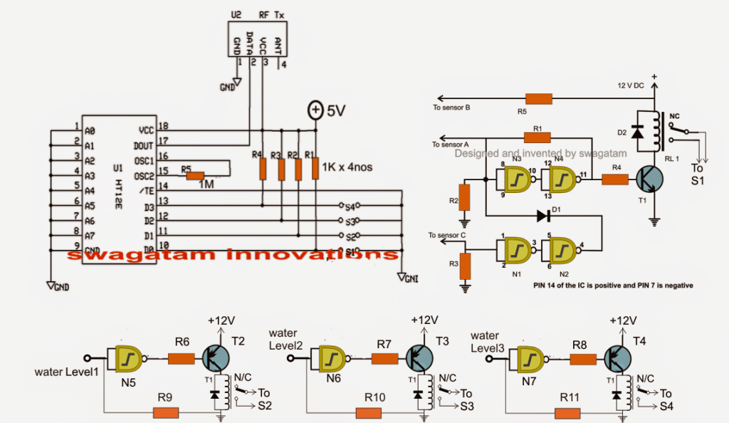
Here we incorporate two separate stages, one is our automatic water level controller circuit and the other is the RF remote control circuit.
Using Tx, Rx 433MHz RF Modules
The remote control has a Tx (transmitter) and and Rx (receiver). The transmitter is triggered through four discrete switches which encode and transmit the signals discretely into the atmosphere.
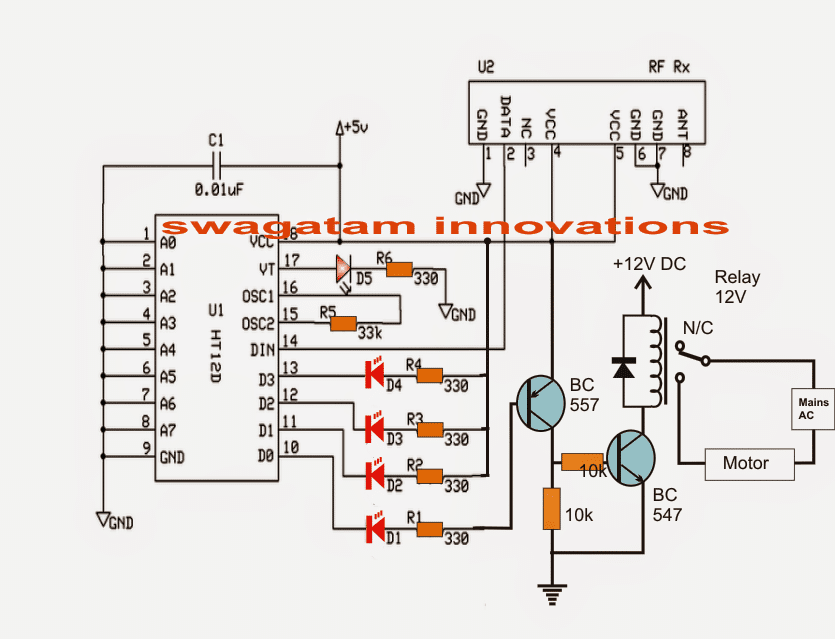
The receiver captures these signals, decodes it and sends it to one of the four outputs relevant to the decoded info.
This output responds by becoming high as long as the corresponding Tx switch is kept depressed.
The idea of the proposed water level controller through a remote control module is to press the Tx switches via relay contacts actuated by the water level controller circuit in response to the various water level conditions, as configured by the user.
The same has been implemented in the discussed design.
Referring to the figure, the gates gates N1 to N4 form the automatic water level controller circuit wherein the motor is switched ON when the level reaches a minimum lower threshold, and is switched OFF as soon as the level reaches the brim of the tank.
Originally Relay R1 was used for activating the motor by wiring its contacts to the motor and mains.
However for the present application, RL1 is rigged to one of the switches of the Tx module (S1)
Meaning now the Tx pin10 is engaged with the transmission of the signals as soon as RL1 is energized which happens on detection of an empty water tank.
Once this happens, the Rx responds by receiving the signals and triggering its own relay connected with the corresponding pinout.
This relay then activates the distant underground or overhead motor for the required water pumping.
The circuit diagram also shows three gates N5, N6, N7 which are configured as NOT gates for sensing the different water levels across the tank while the water is being pumped.
In the course these gates activate their own relays, which in turn close S2, S3, S4 for the necessary transmissions from the Tx to Rx.
The above transmissions are appropriately collected by the Rx, decoded and fed across its relevant outputs for illuminating the connected LEDs.
These LEDs provide the user with the info regarding the gradually filling water tank.
Thus the remote controlled triggering feature of the water level controller facilitates the owner a wireless and hassle free option of monitoring and controlling a distant situated tank.
The following figure shows the wiring details of the Rx or the receiver stage responsible for the toggling of the pump motor and various water level indications, in response to the Tx triggering signals.
Receiver Schematic
The RF modules can be sutudied in detail below:
https://www.homemade-circuits.com/2013/07/simple-100-meter-rf-module-remote.html
Parts List for the water level controller stage (N1----N4):
- R1 = 100K,
- R2, R3 = 2M2,
- R4, R5, R6, R7, R8, R9, R10, R11= 10K,
- T1 = BC547,
- T2, T3, T4 = BC557
- D1, D2 = 1N4148,
- All RELAYs = 12V, 400 OHMS, SPDT, contact amps as per load specs.
- N1, N2, N3, N4, N5, N6, N7 = IC 4093 (2nos.)
The last unused gate (N8) input must be terminated to ground or (+), output may be kept open.
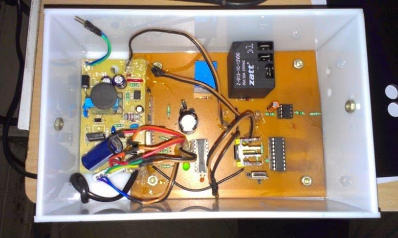
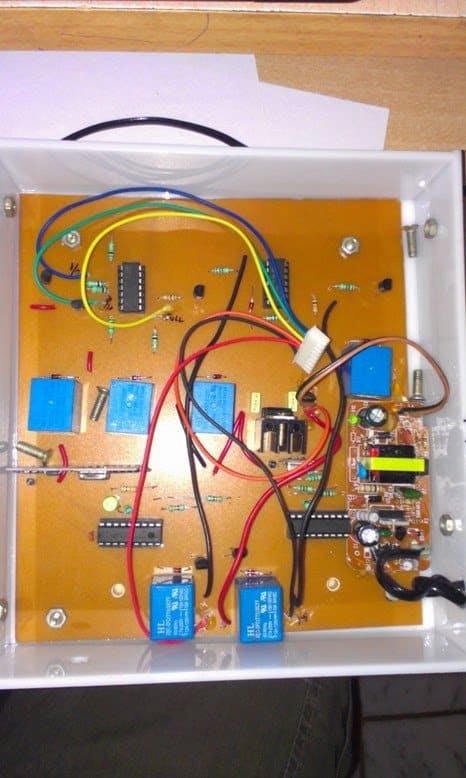
The above wireless water level controller circuit was built and successfully tested by Mr. Sriram kp. The following images exhibit the results of his outstanding efforts:
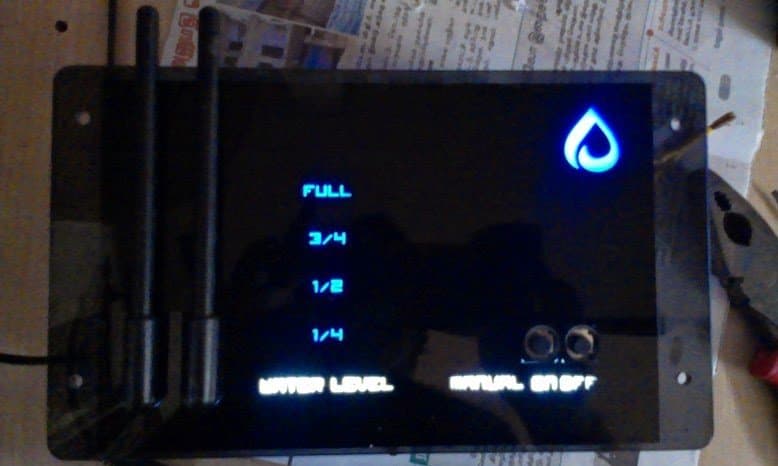


Questions & Answers
Hello Sir. What about the length and the nature of the antenna;. is it coiled reassemble an inductor? and how long should it be Sir?
The antenna can be made by connecting a long flexible wire , around 2 feet long, that’s all, it can be straight or coiled does not matter.
hello?I am not able to clearly understand where the connections of sensors A, B, and C should go in the transmitter circuit. Also, should the IC 4093 levels 1, 2, and 3 be shorted to ground inside the tank? It would be very helpful if you could provide the complete circuit diagram using IC 4093.
Hi, please see the following connection diagram for the tank probes:
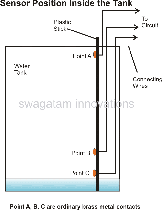
The N5, N6, N7 inputs can be sequentially positioned above the probe B in the tank for monitoring the different levels of water in the tank…
Are the sensor connection points A, B, and C of S1 supposed to be shorted with Level-1, Level-2, and Level-3 points respectively and then connected inside the tank?
Brother, I’m saying that if you could make a complete circuit diagram using the CD4093 IC, it would be much easier for me to understand. So I kindly request you to do that.
Because I am a first-year electronics student, and I have already invested some money in this project.
Hi Priyam,
This circuit was posted many years ago, still, as far as i remember probes A, B, C does not need to be connected with Level-1, Level-2, and Level-3 points.
I would recommend you to go step-wise and first build the basic water level controller circuit using IC 4093 as described in the following article. Once you successfully build and test it then we can proceed to the next remote control version of the design.
https://www.homemade-circuits.com/how-to-make-simple-water-level/
“I have sent you an email. Please check it and give a reply if possible.”
Here’s the detailed tank probe position diagram:
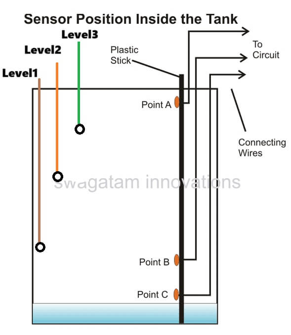
I have checked your diagram, according to me the N5, N6, N7 inputs does not need to be connected with the probes A, B, C. These inputs need to be installed separately, above the point B in the water tank.
Hello Sir.
a. The N5, N6, and N7; are they from the same CD4093 or are we using 2 CD4093 ICs? because the N1, N2, N3, and N4 seem to have depleted the 4 NAND gates contained in the CD4093.
b. N5, N6, N7 are NOT gates. Is it a different IC Sir?
Jedidiah, yes you will need more than one 4093 IC so that the shown number of NAND gates can be accommodated. All the gates are supposed to be from IC 4093.
How about using a NOT gate itself such as 74LS04?
You can use it, but do not exceed 5V for the supply DC.
Thank you
Thank you
hi sir can you please share me the detail of the encloser
The enclosure can be any suitable plastic enclosure, not a metal one…
if possible do have the dimensions of the encloser and stuff , and aslo sir which motor pump is good to use in this circuit can you please tell me
Rishi, you can use small plastic tiffin boxes as the enclosure, for both the units…any moderate power motor pump can be used if the relay is a 30 amp relay…
hi sir thanks for responding , I’m looking to add two tanks with two different transmitter unit and one receiver unit setting the unique code by dip switch on both end. but the thing is the commonets you use in this circuit are not avilable to purchace in North America do we have any substitute for component or for circuit ? it will be really helpfull
Hi Rishi,
The components used in the above circuit are standard components and they cannot be changed. I think you should try an online components spare part store and check the availability, I am sure you will be able to get all these parts online easily…
Hi swagatam
Thanks for clearing that up for me!!!! Your quick response is wonderful. Great website!!!!
It’s my pleasure Norman.
Hi Swagatam,
The above receiver circuit shows that D0-D3 of HT12D to produce a low output when the HT12E D0-D3 receives a ground pulse. I saw another posts that indicated a high at HT12D D0-D3. I’m confused!
Hi Norman,
D0-D3 of HT12D produces a low output when the when the HT12E D0-D3 receives a ground pulse, this has been tested and verified practically by the user discussed in the article. However, I myself have not verified it yet.
Need contact detail of PCB or Kit seller at Kolkata.
Sorry, I have no idea about it…
What is the battery life of this transmitter and receiver circuit ? In the comments I notice that there are comments which says that the circuit drains the battery very soon. I am planning to use it for my home purpose. I just need the water level indicator with alarm. i dont need the motor controller, etc. Is a readymade circuit available ?
Hi,
I didn’t understand what is N1, N2…. N7??
Hi, those are nand gates found inside the IC 4093
If you need it only for indication purpose then you can remove all the transistor and NAND gate IC based stages, and use only the basic Tx, Rx modules with LEDs. In the transmitter module the S1, S2, S3, S4 points could be used as sensors for immersing inside the tank at different heights, for sensing the water levels at those points.
The current consumption will be quite low, but till above 50 mA, and you will have to depend on a Li-Ion battery for long back up times.
Hello Sir, im trying to implement the above circuit. however the circuit is supposed to be battery operated. The transmitters have a current consumption of about 9 – 40mA (for ASK) which is not feasible as it’ll drain the battery quickly. Can you suggest any RF transmitters (433 MHz) having low power consumption. I have searched and found out that OOK modulation consumes low power. Can you suggest me some OOK transmitters and their internal circuit diagram ? Transmitters are desired to have a current consumption of about 4.5 – 5 mA for 5 V input and a range of about 100 – 300m
Hello Mihir,
you can try searching for “BC48R2020 315M/433MHz OOK Transmitter” you will be able to find the original HOLTEK datasheet
Hi Swagatam,
This remote-controlled-wireless-water-level looks good but I want only indicator not any relay to run motor. Can you please provide me simple circuit which will just indicate me about level through LED on unit which will be at lower level and people can act accordingly.
Looking forward for your response.
Hi Prem, you can try the following diagram:
The gate is from IC 4093.
Repeat the above circuit for pin11, 12, 13 of HT12E transmitter circuit.
In the receiver eliminate the transistor relay stage, and use only the LEDs for getting the required indications.
Please
Tell me resistance watt
all are 1/4 watt
Hi swagatham,
Thank u very much to your valuable reply that published in ur web page!.
Now I have an another doubt about the tx contro circuit.As you say I used a +5v relay in the circuit then ll compelsed to reduce the value of R5 as 220 ohm. Now it is working but some time do and not is the condition. That is why I cannot depend this tx vontrol unit. Actually what cn I do to get the accuracy for the circuit that need to be work properly means when ABC touches the water relay want to close and when AB leaves from waterand C lonely in water want to open the relay. Please be command.
And you can watch your corcuit how I made in reality: by opening the link
imgur. com/u5Edvtv and w.w.t.l control
Thanking you.
Thanks Abdlu, It's R4 and not R5 which needs to be changed to 220 ohms, I hope you did this right?
To increase accuracy, use a higher voltage supply inside water and check the response….if you are using 5V inside water then that might not work properly.
sorry your link is not working
hi swagatham,
I have a doubt about the above given article.can I control the tx and controling circuit completely with a +5 v power supply insted of +5,+12?.I want to control the tx circuit completely with a +5v supply by omiting +12v.is it possible? if so what changes need in the values of resistors?.please be helped
Hi Abdlu, it is possible if you don't intend to use a relay or if you replace the 12V relay with a 5V relay….no other changes would be required
Hai I have a problem and doubts in the circuit I have tried and failed so please give your number so I can contact u
Hi, you will need to build the various stages separately and confirm them separately before making the final unit…
you can specify your faults here I'll try to help
Hi I have tried this circuit but its not working I need help
pls give u moter dry run protection circuts
hi swagatam
After long time i build this circuit with all tests, but now i have one problem with range. When i operate rf module at a distance of 15ft each are at different room it works, but when i go to building terrace there is no activity at receiver. I have question regarding anteena,
1: What is length of anteena at both location?
2: What are the type of anteena?
3: i have 3 different pair of RF module, in which transmitter operate alternate but receiver section continuously on to receive signal. I used one common anteena for transmitter section and one common anteena for receiver section. is this ok?
4: is there need to use seperate anteena for separate receiver and transmitter?
please provide me guidance at this end point.
can u show me the complete circuit diagram
hai could you plese tell me that total howmany wires to be immersed in tank (3 sensors & 3 water levels)?…
for controlling the pump there are three wires to be inserted as shown in the first diagram (wires A, B, C), the remaining wires shown can be used only for indication purpose to learn the exact position of the water through the respective illuminated LEDs.
Can u plz post the complete ckt diagram once
Hi swagatam,
I constructed this circuit and it works well but the range is only 1 meter. I used 1 ft wire as antenna. Can you advise what could be the reason for low range.
Hi Anup, 1 meter is very less, there could be some problem with your remote control modules, please check it separately ad make sure it's giving at least a 50 meter transmission range, otherwise you can think about getting it replaced with a new one…
Nice
Hi swagatam,
If we install same system in two adjoining buildings just 10 meters apart, will they interfere in each other operations .Pls advise.
Hi Anup, yes certainly they will interfere, since the range of the system can be well over 50 meters.
Hi Swagatam, Just to clarify level1,2 and 3 are for LED indication of water level in the tank.Sensor A,B and C are to be dipped in OH tank. Can you pls clarify, sensor A to be kept at level to stop the motor and Sensor C at a level to start the motor.
Can you make circuit to replace these sensors with Ultrasonic switches.
Hi Anup,
yes level 1,2,3 are for indicating the different water levels by triggering the relevant Tx switches.
for knowing the exact positions of the A,B, C sensors you can read the following article, which has all the details specifically covered:
https://www.homemade-circuits.com/2011/12/how-to-make-simple-water-level.html
Ultrasonic sensor is feasible but can be too complex and expensive, a better alternative could be in the form of float switches, as explained here:
https://www.homemade-circuits.com/2014/05/making-float-switch-for-corrosion-free.html
dear sir I am created ur circut. good the circuit is working well. thank u… I have a doubt. .. I have 4 water tank in my house… so I want to know level of water…. so how to install the circut at the 4 water tank…?? supose I installed 4 tx and rx for the water tank at the same plase in low distence…. have any problem in the data transmission?
pins 1 to 9 are the address pins of the ICs….you can select or eliminate their connections with the ground for creating a desired code…this code must be identical with the Tx/Rx modules…..but this code should be differently wired across other Rx/Tx modules for getting unique responses from each of the modules.
thanks Arun, I am glad it's serving the purpose for you.
yes you can use 4 separate identical units for monitoring four water tank levels.
just make sure to use different address pin configurations for the Tx/Rx sets for the 4 units, this will ensure proper functioning of the units without cross interferences.
the address pin configurations must be identical for a particular Tx/Rx set, but different to the other Rx/Tx sets
hello Sir , Nice Project will you please tell me how can i make panel just like you shown in image "2.bp.blogspot.com/-OA0fphjw2tg/U7-5JL16zKI/AAAAAAAAHiA/w_dK1r4SwRU/s1600/kNtUeTu.jpg" , Thanks
Hello Tariq, you'll need to design a negative film from a photographers studio, then place the respective LEDs behind this film after positioning it over the enclosure
in pics last pics show display. what is this & how he made?
I did not notice the address pins were differently set….
NO that won't work according to me.
sir but from 1st encoder 1 signal is send through TX and from second encoder send from same tx then how RX receive signal means for which signal kept in loop for forwarding encoder
It seems OK to me, and should work, try with two modules first…. if it works then you can try putting more in parallel
HI I LITTLE CONFUSION, I MADE SOME CHANGES. i WANT TO OPERATE TWO TO THREE DIFFERENT LOCATION UNIT (TANK) AT ONE PLACE MEANS UNDER GROUND TANK LEVEL & TERRACE TANK LEVEL CONTROLLED AT MOTOR AREA. FOR THAT I WANT TO USED 2 TX & 1 RX. AS shown in this link https://drive.google.com/file/d/0ByzJSqCugD_yVzJtZU1waDctR0k/view?usp=sharing
please confirm this if possible how much we can use encoder & decoder on single module.
Ashok, sorry I could not understand any of the above questions
Sir i have another question for start & stop motor on following condition:
1: When low lvl at over head tank off motor start at that point under ground tank low lvl should be on.
2: In above condition if Under ground tank low lvl off motor stop.
3: when motor start it start still upto over head tank high lvl on. when high lvl on motor stop.
can you tell me how this assemble.
it's just number cut outs made over a smokey glass and with blue LEDs at the back
as in above comment you said that 9 volt battery is used at TX section, but in diagram 12 volt relay is used. Instead of relay section at TX can we use any float switch or reed switch? which is long life for circuit and neglect corrosion of wires.
the relay voltage should be equal or match with the supply voltage, that's an understood fact, I might have said it by mistake or a typo.
Hi sir, 1: If i used 2 pair of RF module, can any transmitter signal receives by both receiver receives signal or not? if not so how to adjust any settings for this confusion? 2: Receiver receives signal if i place both unit (RX & TX) at different room?
i hope you understand my question.
Hi Ashok, if you 2 pairs of Tx/Rx modules, the signals will not interfere with each other provided you keep adequate distance between the Rx (receiver) modules, because the two pairs will have different operating frequencies determined by the setting of the "adrress pins" of the two ICs so it's highly unlikely to produce any interference.
Dear bro i need only simple wireless water level indicator circuit diagram, no need automatic pump switch.could u develop it?
understood bro, but still you would require the above explained wireless Tx, Rx set up, only the relay stages will not be used….I'll try to post it for you as a new article if you are OK with this.
Dear bro i live in 1st floor and my water tank is in 6th floor roof top.Now i want to monitor my water level of my tank from 1st floor.Do u have any simple circuit diagram with LED and Sound indicator?I also want to avoid wire from 6th floor to 1st floor to see the water level.Please help me.
Dear Bro, for a wireless system you may have to employ the above circuit because it probably looks quite perfect and reasonable.
Hi Swagatam, I plan to make this but would like the transmitter to be powered by a battery as I don't have an electrical connection near the tank. Do you know what is the approx. current drain for the transmitter and so can estimate how much may a 9V battery last. I would like to go with this solution only if the battery lasts for at least 3-4 months so that changing it isn't cumbersome.
Hi Vijay, the transmitter will consume not more than 3 to 5mA, so it can be easily powered from a 9V battery and will last for years ….because the Tx will consume only when the its transmitter buttons are pressed, otherwise it will be negligibly small..
printed pcb is avallbul
sorry, not available
assembled circuit isavailable
sorry, not available
Swagatam I have connected the sensors inside the tank but when the the water level goes below s4 the motor starts . I have placed sensor B at the bottom ,A just above sensor B, and C at the overflow level. Kindly advice.
Hafeez, please see the correct sensor positions as given in the following article, what you have done is not correct:
https://www.homemade-circuits.com/2011/12/how-to-make-simple-water-level.html
Swagatam many thanks completed the ckt successfully,
Is it possible to make the sensors to work wireless?..
That's great Hafeez, congrats on that!
to make wireless sensors you may have to incorporate another set of RF modules….. won't be a good idea because that could make the unit very complex.
Swagatam I have sorted the issue out now everything works fine except the d4 LED, which is not lighting up when I short the s4 switch, i have checked the connection of the LED evrything is perfect, can u plz help me out.. Relay 4 is working but led is not lighting up
That's great Hafeez, check the voltage at D3 output of the receiver IC after removing the LED with respect to positive. If the meter shows a voltage reading in response to the relay operations would confirm a faulty LEd otherwise one of the the ICs could be malfunctioning
Swagatam I've cross checked the whole circuit everything is perfect abc contacts are not working , when I connect the led sensors to sensor B the relays are working fine. In the controller circuit when I short the sensor B with the ics 8,9,&10 leg the relay is working I.e s1. If I short the sensor b with a it's not working , kindly help}
Hafeez, the circuits have been tested successfully by other members of this blog, so it would be difficult for me to troubleshoot a specific problem in your design.
If you finding the above water level controller circuit difficult you could probably try Googling for an easier alternative and try making it for the same.
Once you succeed with the water level circuit section, you could go ahead with the above explained remote control integrations.
Swagatam I recreated the circuit as per ur suggestion my issue over here is when I short the sensors abc no action is performed, I checked the relay it's working good.. And also receiver communication light d5 is not turning on when I checked the voltage it shows 0 across d5. D1- d4 LEDs are lighted up constantly , kindly help
Hafeez, it means your water level controller circuit has problems, you may take the help of the following article and first make sure your water level circuit works correctly, otherwise you won't be able to proceed with the above remote control integrations.
https://www.homemade-circuits.com/2011/12/how-to-make-simple-water-level.html
Thank u… I will try that. Check whether the capacitor placement is correct in my sketch…
imgur.com/XJlc4sb
yes that's correct. also connect a 100uF capacitor across the relay coils if possible, any smaller value will also do.
Hai, I got one big problem in the ciruit which i made. At starting the circuits works fine. After some time, the four relays in the TX sections are started flickering continuously, results the LEDs at the RX section also flickering. After when I took out the wires from the tank means the relays stopped flickering. And when I shorted the wires manually, the relays working good. But again if I dip the wires in the tank means the relays started flickering. Why it is happening and how to solve this prob??
Hi, as suggested to Mr. Hafeez above, you too can try adding 0.22uF capacitors across all the 2.2M resistors, furthermore these 2.2M could be replaced with 10M resistors for increasing the sensitivity of the gates.
also connect a 100uF capacitor across all the relay coils.
Thanks for ur reply . I have connected 10 uf capacitors across the relay coil the sound is gone now but the RL4 light is on in the receiver module when I disconnect the cable the light is still on there is no movement in the RL4. And when I dip all thr six cables inside the water level indicators led is not lighting up . When I short the cables it's lighting up . As u said I'm using a perfect DC supplies.
You can try making the gate resistors (R2,R3,R9,R10,R11) higher than 2M2….try 10M resistors.
also please connect 0.22uF caps parallel with these resistors.
Swagatam I need ur help very urgently, when I short the level indicator wires one of the relay makes a weird noise, I have checked all the connections evrything seems to be fine. And I have replaced the relay too but again the sound is there in the receiver section the d4 led keeps on blinking if I short all the wire of the level indicator it makes sound and if I short one by one no problem at all it works fine. When I short any one of the transistors base and collector the sound goes off . Kindly help or else I need to start the ckt once again from the scratch
In the receiver section put a 10uF/25V capacitor parallel to C1, I hope you are using perfectly regulated supplies for the 5V and the 12V DCs…..
Hafeez, try connecting a 100uF/25V capacitor parallel to the relay coils, or alternatively you can try connecting 10uF/25V capacitor across base/emitter of the transistors.
hi Swagatam ..i am a new comer in this field , interested in your blogs .its avery nice activity ..i like to modify ur wireless water controller with float switches in transmitter section (minimum 2 switches ,low and high ) with 2 nos 5volt relays ,,please check and sugesst the mistakes
thanks
Ashokan Eluvangal
Thank you Ashokan, In the transmitter section you will require the top/right water level controller circuit. Connect terminal B to both the poles of the float switches (reed switches) and connect terminals A and C to the respective N/O contacts of the reed switches separately depending upon how and where the switches are positioned inside the water
Swagatam I need to toggle the motor manually coz we use the same for watering plants, can u give me an idea how to use manually by using 2 switches
Hafeez, use one of the 3 vertical terminal group from the DPDT and connect it as explained in the previous comment
Swagatam I never got spdt ac switch instead I got 6 leads dpdt switch , can u help me how to connect it
Hafeez, you can use a SPDT switch with the motor wire which connects with the relay.
Disconnect the motor wire which is connected with the N/O contact of the relay and the this motor wire with the center lead of the switch.
Connect the outer two leads of the switch with the relay N/O and the relay center pole
Hai, I successfully made the above circuit. Here are the images:
imgur.com/kNtUeTu
imgur.com/Mgm385N
imgur.com/9jQOJCi
My heartly thanks to u for clarifying all my doubts regarding the circuits…
Thankyou very much…
Hi, thanks that's great, I'll make sure these get posted in the above article.
…it's my pleasure
Swagatam thank you very much mate , sorted out the issue as u said led has been connected wrongly , now the circuit is working fine. One last question whether the circuit is for UGT or OHT, if this is for UGT guide me how to use it for OHT.
Many thanks
You are welcome Hafeez, the circuit could be used for over head, or underground tank applications, it will depend on how you place the sensors inside the tank and how you configure the relay N/C N/O contacts with the remote control inputs or with the motor.
The circuit has a wide range of application.
I think u took in other way around. My issue is the d1 led is working fine. But d2,d3,d4and d5 is not working. But when I short the leads of tx sensor b with water level 1 2&3 the relays are working fine but the LEDs are not lighting up
Hafeez, it means your Rx and Tx are not connecting with each other or may be something's incorrect in the circuit, check the units manually by disconnecting from the relays.
or may be you have connected the LEDs wrongly.
Swagatam I have built this circuit my issue over here is the led d0 is lighting up , but none of the other LEDs are not powering can u help me . And also can u guide me how to place the sensors.
Sorry it's a mistake led d1 is powering on but other LEDs are not . Relays are working fine , my issue is only with the led. One more clarification is this circuit is for UHT or OHT. If it is for UHT please provide me the details to use for OHT purpose.
Hafeez, D0 of Rx corresponds to D0 of Tx, If D0 (S1) of Tx is triggered via RL1 or by any other means then D0 of your Rx will be ON, check this manually to confirm and rectify the issue
Hai, In RX section, how to make the relay activate after 5 seconds when switch1 is pressed in TX?? y i need is, everytime when I power ON the circuit means the LEDs and the relay activated for 2 seconds and then they get OFF when paired to the TX section. so wat I need is, when the sw1 is pressed means the LED D1 can glow but the relay should activate after 5 seconds only. what I can do for that??
yes 1N4002 will do, the diode connections are correctly drawn in the diagram.
yes that's perfect.
Can I use 1N4002 instead of 1N4007 ? will it make any difference?? and is the diode placement is correct in the diagram?? cathode of the diode is connected to ground and anode to the emitter of the transistor BC547??
Thanks… I made a sketch. check whether the capacitor and the diode placement is correct… imgur.com/AHPtBPl
but this will also mean that the relay will switch off after 5 seconds every time….
connect a 1000uF capacitor across base and ground of the transistor and connect its emitter through two 1N4007 diodes to ground…..
The automatic actions are performing in TX1, RX1. Manual control is performing in TX2, RX2. TX1, RX2 is placed in one board which is kept near the tank. TX2, RX1 is placed in one board which is kept in my home. Your above circuit is done with TX1, RX1. What is the use of TX2, RX2 is… simply U can understand by the below diagram.
imgur.com/vGcNJeH
so the sensors from the IC is always connected to the tank sensor bcoz of they connected to the NC. In relay2, NO is connected with +12v dc. So the process will work as ur above circuit only. Example, Now the tank consists of half tank water, I need to turn ON the motor manaully means i will press "push to ON" switch connected with TX2 which is placed in my home. when i press the switch means the relay1 wil get activated and thus the connection between the tank lower sensor and the IC lower sensor B will get disconnected. so the IC wil assume that the tank is empty. so the motor will get activated. Then the motor will automatically get OFF when the tank is full. suppose the motor is running, i need to stop the motor means, i will press the another "push to ON" switch in the TX2, then the relay2 will get activate, so the sensor A from the IC will get connected to the +12v in the relay. so the IC will assume that the tank is full and the motor wil get OFF.
I removed the ICs from the TX1, RX1. The TX2, RX2 is working good. Then i removed the ICs from the TX2, RX2. The TX1, RX1 is working good. Now if I place all the four ICs in the TX1, RX1, TX2, RX2… both circuits are not working. Some signal is interfering when both circuits are connected. Pls help me…
Hafeez, this has been already followed in the relevant modules, but the response is still negative.
To resolve this issue in tx1 and rx1 all the pins on left side is connected to ground. Same wise in tx2 and rx2 instead of connecting all thr pins to ground ask him to leave any of the pins open for example pin1 in rx2 and pin 1 in tx2 I guess the cross communication will be solved
sorry it's beyond my control, it's something connected with cross interfence of the two carrier signals which could be cancelling each other.
I think if one Rx/Tx is based on AM, while the other in FM, things would get solved…I'll try to figure out an AM design if possible.
Hai, I made this circuit with two RF module TX1, RX1 and TX2, RX2. One is for above circuit function and another one is for manually ON the motor. TX1 , RX 2 is placed in one board and TX2, RX1 is placed in another board. In TX1 and RX1, I connected all the address pins to the ground. In TX2 and RX2, I left A6, A7 and connected rest of the address pins to the gorund. Your above circuit is connected to TX1, RX1. All are working good, except TX1, RX1. when i placed the encoder, decoder ICs on the slots means, the both TX1, RX1 and TX2, RX2 are not working. When i removed the encoder IC from the TX1, the TX2, RX2 is working. Again if I place the encoder IC in the TX1 slot means the TX2, RX2 are not working and the four LEDs in the RX1 is always glowing, the LED at the pin 17 is not glowing. I checked the connections. All are correct. Dont know where is the problem is… Please help…
Hi, it seems some factor may be interfering across the two modules which is even unknown to me.
By the way the motor which you intend to toggle manually, is it the same one which is also used for the automatic actions?
If it is then a separate RX2 wouldn't be required, TX1 and TX2 could be used with RX1 for implementing both automatic and manual toggling.
Hai, In RX section, can I connect two 12v relay in same BC547 ?
Hi BC547 will bet slightly hot, use 8050
Swagatam the tx circuit ic 14th leg is connected to ground?
Hafeez, yes it's connected to ground (supply negative).
Am using blue LEDs at D1-D4. The brightness is too low. So can I use 75-100 ohms resistor instead of 330 ohms??
change the LEDs to RED, do not lower the resistor values.
Hai , I made this circuit. but some problems. In receiver section, the led D1 is always in ON state only. Means, if the water level is below the low sensor means the D1 led is in ON only and the relay connected through the D1 is not activating. I tested the relay separately and its working. but the relay is not working when i connected through the D1. Is the above circuit is fully correct?? Pls help…
D1 will be on if D0 output of the IC is low and this will happen if the transmitters SW1 switch is in closed position.
may be in the first circuit RL1 is wrongly connected with SW1 of the transmitter circuit….please check it.
What is the purpose of using 1n4148 diodes d1and d2 across the relay ? Usually we use 1n4001 series diodes ryt. U have mentioned about only d1 and d2 and wat about other diodes?
all diodes are rectifier diodes, could be 1N4148 or 1N4007.
the relay diodes are for cancelling the back emfs from the relay coil during switch OFF periods for safeguarding the transistors.
Hi swagatam can u suggest any relay with p/n
Hi Hafeez, Please refer to this article for more info:
https://www.homemade-circuits.com/2012/01/how-to-understand-and-use-relay-in.html
Hai, I am using two pair of RX/TX. TX1, RX2 in one circuit and TX2, RX1 in another circuit. Both circuit are in different location. So can I connect TX1, RX2 in one single antenna and TX2, RX1 in another single antenna??? If I connect the TX1, RX2 in single antenna means will it affect the communication because a single antenna have to do transmitting and receiving simultaneously at the same time??
Hi, I don't think that would be a good idea, and it won't work. Use separate antennas for each unit.
Swagatam I tried getting 12v 400ohms relay but over here they have only 250ohms, will that do or I need to buy exactly the same one. And in my home we use 1 hp pump will there would be any issue using those relay
Hafeez, no problem, it will also work but make sure the contacts can handle in excess of 30 amps.
Hi swagatam hope ur doing good. I need ur help in making this circuit . I need to clarify couple of things from tx and water level circuit.
1. Which type of sensor is used in tx circuit
2. Can u plz mention the pin no of not gates in water level circuit
those terminals will be immersed inside the tank at different depths as desired by the user for getting the indications of the relevant water levels while the tanks fills.
In water level ckt , n5 n6 &n7 u have mentioned water level 1 ,2 and 3 , to be precise the input of not gates where does it get connects
I can't see 1, 2, 3 do you mean A, B, C??
Swagatam what does water level 1 ,2,3 means in water level controller ckt.
Hi Hafeez,
the sensors are just wire ends of the extended terminals appropriately tinned with solder and immersed at the relevant depths.
please refer to the datasheet of the IC 4093, you will able to see all gate pinouts in the given diagram, which you can directly apply for the above design
how abt now???
imgur.com/q7x5e2F
ok. Thankyou…
it's correct now, include the relay diode also
I modified. check whether the below circuit is correct to operate a 5v relay from the docoder IC?
imgur.com/jHk45S7
no still not correct, one lead will go to collector other to ground.
Hai, Thankyou very much for the circuit… One doubt, In receiver section, the relay is connected 12v and the transistor and all connected with 5v. will it wont create short circuit??
You can remove the LED but not the resistor, keep the resistor as it is.
The relay connection is incorrect in your diagram….put it right in the place of the 10k resistor and remove the 10k resistor, meaning simply replace the relay coil with the 10k resistor position (collector and ground)
the monostable link that you have shown is OK, you can use it.
you can use it directly in place of the 12V relay, no modifications would be required.
Hai, In RX section, if I dont want the LED at D0 means shall i remove the LED and 330 ohms resistor and connect the D0 directly to base of BC557??
And Is the below circuit diagram is correct to connect a 5v relay to BC557??? Is that 10k and grounded is needed?? or is that enough to connect the collector of BC557 directly to 5v relay without 10k and gound??
imgur.com/ALw0hi9
Thankyou, I like to connect another 5v relay in the receiver section. So can I connect that in the same BC547?? or do i need any extra components to connect 5v relay??
Thanks, no it will not create any short-circuit anywhere, if you intend to use a 5V relay, you could eliminate the BC547/10k stage and connect it directly at the collector of the BC557.