Although a quadcopter remote control circuits can be very easily procured from the market or from any online store, an avid electronic hobbyist is never allowed to learn how actually these function and whether or not these can be built at home?
In this article I have explained how to build a simple quadcopter remote control circuit using discrete components and using RF remote control modules, and without involving the complex MCU based circuits.
The step by step guide will actually make the interested hobbyists understand how simply a quadcopter can be controlled using a PWM concept.
We have already learned the quadcopter basics, now let's investigate a the remote control section which will ultimately help to fly the unit remotely.
Basic Modules Required
The main ingredients that may be required for the project are given as under:
We will fundamentally require the following 3 circuit stages:
1) 4 way RF remote control Tx, Rx modules - 1set
2) IC 555 based PWM generator circuits - 4nos
3) BLDC motor controller circuits - 4nos
Since it's a homemade version, we can expect some inefficiencies with the proposed design, such as the absence of joysticks for the controls, which are replaced with pots or potentiometers, nevertheless the working capability of the system can be expected to be on par with the professional units.
The handheld PWM transmitter unit will basically consist the Tx remote module integrated with 4 discrete PWM control circuits, while the quadcopter will need to be enclosed with 1 Rx circuit integrated with 4 discrete BLDC driver circuits.
Let's begin with the quadcopter motor circuits, and see how the BLDC motor controller needs to be configured and attached with the Rx circuit.
Quadcopter PWM Receiver Circuit
In one of the previous posts I have explained how a versatile BLDC motor controller could be built using single chip, however this design is not designed to operate relatively heavier motors of a quadcopter, therefore it may not be suitable for the present application.
A "big brother" option for the above circuit is fortunately available and becomes perfectly suitable for driving quadcopter motors. Thanks to TEXAS INSTRUMENTS, for providing us with such wonderful single chip application specified circuit modules.
To learn more about this high current BLDC driver IC, you may refer to the following pdf datasheet of the same
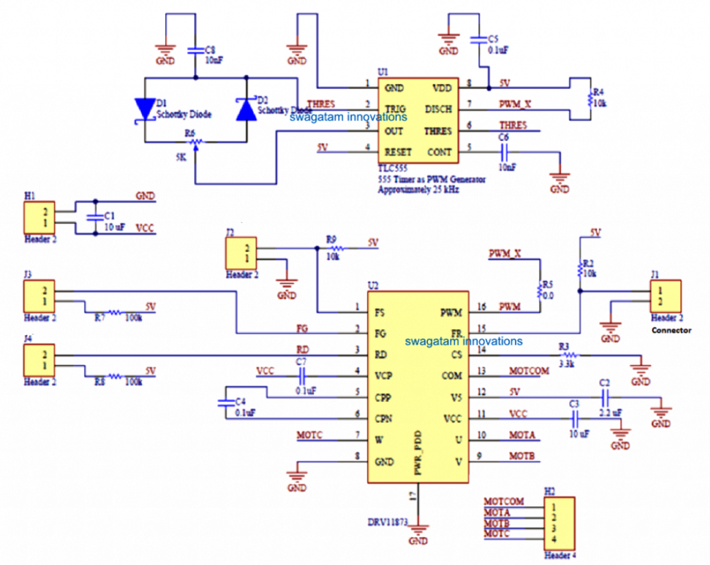
The set up below shows the complete circuit schematic of the quadcopter motor driver controller using the DRV11873 IC which is a self contained low current BLDC motor circuit consisting of all the required protection features such overload protection, thermal protection etc. This module basically forms the ESC for our present quadcopter unit.
For more info on this design and PCB details, you can refer to the original document below:
http://www.ti.com/lit/ds/symlink/drv11873.pdf
How it Works
The FS and FG pinouts of the IC are for enhancing the IC with added controls through external circuits, since we are not using these features in our design, these pins may be kept unused and terminated to the positive line through a 100K resistor.
The RD pinout of the IC decides the rotational direction of the motor. Connecting this pin to Vcc via a 100K resistor allows an anticlockwise rotation on the motor while leaving it unconnected does the opposite and allows the motor to spin in the clockwise direction.
Pin#16 is the PWM input is used for injecting a PWM input from an external source, varying the duty cycle of the PWM alters the speed of the motor correspondingly.
The FR, CS pinouts are also irrelevant to out need and can be therefore left unused as shown in the diagram, and terminated to the positive line through a 100K resistor.
The U, V, W pinouts are the motor outputs which needs to be connected with the respective quadcopter BLDC 3 phase motor.
The COM pinout is for connecting the common wire of the 3 phase motor, if your motor does not have a common wire, you can simply simulate it by connecting 3 nos of 2k2 resistors to the U, W, W pins and then join their common ends with the COM pin of the IC.
The schematic also shows an IC 555 configured in the PWM astable circuit mode. This becomes a part of the circuit module and the PWM output from its pin#7 can be seen connected with the PWM input of the DRV IC circuit in order to initiate the 4 motors with a constant base speed and to enable the motor a constant hovering speed at a given spot.
This concludes the main ELC circuit or the BLDC driver circuit for out quadcopter design.
We will need four such modules for the four motor in our quadcopter design.
Meaning, 4 such DRV IC along with the IC 555 PWM stage will need to be associated with each of the 4 motors of the quadcopter.
These modules will ensure that normally all the 4 motors are set at a predetermined speed by applying a fixed and identical PWM signal to each of the relevant DRV controller ICs.
Now let’s learn how the PWM may be altered through a remote control in order to alter the speeds of the individual motor using an ordinary 4 channel remote control handset.
The RF Receiver Module (PWM Decoder)
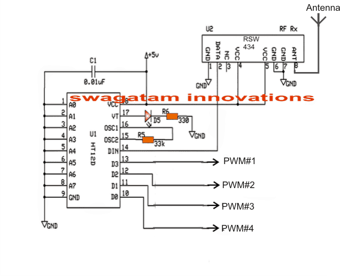
The above circuit shows the receiver remote RF circuit which is supposed to be accommodated inside the quadcopter for receiving an external wireless PWM data from the user’s remote transmitter handset and then process the signals appropriately in order to feed the accompanying DRV controller modules as explained in the previous section.
The 4 outputs named as PWM#1….PWM#4 needs to be connected with the PWM pin#15 of the DRV IC as indicated in the previous diagram.
These PWM pinouts from the RF receiver unit becomes activated whenever the corresponding button is pressed by the user in its transmitter handset.
How the RF Transmitter needs to be Wired (PWM Encoder)
In the above section I have explained the Rx or the remote receiver circuit and how its 4 outputs needs to be connected with the quadcopter motor ESC driver modules.
Here we see how the simple RF transmitter needs to be created and wired with PWM circuits for transmitting the PWM data wirelessly to the quadcopter receiver unit so that the speeds of the individual motor is controlled simply with a press of a button, which ultimately cause the quadcopter to change direction or its speed, as per the users preferences.
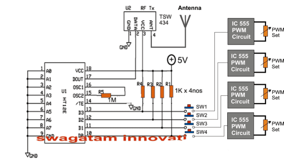
The circuit shown above exhibits the wiring details of the transmitter module. The idea looks pretty simple, the main transmitter circuit is formed by the TSW434 chip which transmits the encoded PWM signals into the atmosphere, and the HT12E which becomes responsible for feeding the encoded signals to the TSW chip.
The PWM signals are generated by 4 separate IC 555 circuit stages which may be identical to the one which was earlier discussed in the DRV controller module.
The PWM contents of the 4 ICs can be seen terminated to the respective pinouts of the encoder IC HT12E through 4 discrete push buttons indicated as SW1----SW4.
Each of these buttons correspond and toggle the identical pinout of the receiver module which I have explained earlier and indicated as PWM#1, PWM#2…..PWM#4.
Meaning pressing SW1 may cause the PWM#1 output of the receiver unit active and this will pinout will start feeding the received decoded PWM signals from the transmitter to the associated DRV module and in turn cause the relevant motor to change its speed accordingly.
Similarly, pressing SW2,3,4 can be used for influencing the speeds of the other 3 quadcopter motors as per the users wish.
IC 555 PWM Circuit
The 4 PWM circuits shown in the above RF transmitter handset can be built by referring to th following diagram, which is exactly similar to the one which was seen our DRV controller ESC circuit.

Please remember that the 5K pot could be in the form of a usual pot and this pot could be used additionally with the buttons for selecting different speeds on the corresponding motors.
Meaning by keeping a selected button pressed and simultaneously moving the corresponding 5KPWMpot one can cause the quadcopter to increase or decrease its speed in the intended direction.
Alternatively the PWM could be initially set at some higher or lower level and then the corresponding button pressed to enable the corresponding quadcopter motor to attain the preferred speed, as per the PWM setting.
Quadcopter Motor Specification
The above explained Qiadcopter remote control circuit is intended to be used for display purpose only, and cannot be used for lifting loads or a camera. This implies that the motors used in the design should be preferably a low current type.
The DRV11873 IC is designed to opeate motors rated at 15V, 1.5 amps or around 20 watt motor...so any 3 phase BLDC motor rated at 15 to 30 watts can be used for the purpose.
The battery for this quadcopter design can be any 12v Lipo pr Li-ion battery capable of supplying 15V peak at 1.5 amps continuous current.
Specification Details
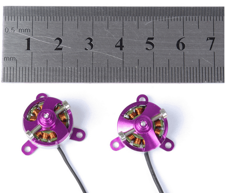
1306N Brushless Outrunner Miniature DC Motor
Type: Micro Motor
Construction: Permanent Magnet
Commutation: Brushless
Speed(RPM): 2200rpm/v
Continuous Current(A): 1.5~2.6A
Voltage(V): 7.4~11.1V
miniature dc motor: AX-1306N
weight: 8g
diameter of shaft: 1.5mm
Battery LI-PO: 2-3s
operating current: 1.5~2.6A
max efficiency: 67%


Questions & Answers
Sir u said that in transmitter side by varying the pwm with the help of pot we can adjust the speed of a motor. I have a doubt sir. In receiver side it receive a signal. When a signal arrives it run the motor. How can u send the pwm signal on receiver side motor because when a receiver accept the transmitted signal it has been decoded by the decoder ic and following pin will tends to high. My question is how the decoder ic output varies when the pwm is changed because output from the decoder is constant right?? I did a remote car by using ht pair ice with ask transmitter and receiver this is my doubt sir??
Vijay, It functions exactly as voice signal is transmitted on radio.
The PWM ride over the RF carrier waves and reach the receiver where these are decoded back and fed to the BLDC driver IC, the BLDC IC amplifies the PWMs and drive the motor with the same amount of switching and apply the intended speed on the motor.
Sir I read what you have said and I had the same doubt as him…also how does the pwm output when received by the receiver move it's directions respectively ?
Sir I read what you have posted. ….I still have the doubt like how does varying the resistor values affect the directions in the receiver end?
Monikka, the quadcopter will stay stationery as long as all its motors are at exactly the same speed, by varying the PWM we are able to alter the speed of the one of the motors which makes the quadcopter lose its uniformity and its slower motor side tilts downwards which in turn causes it to move on that direction.
OK sir. Thanks for the information
sir i will like an image of at list the integration of one of the DRV8313 and sir what is the name of the IC were the anterna is attarchto.
Pro, just connect all the EN pins with a 5V supply and join all the IN pins together and connect with the selected output pin of the receiver Rx decoder IC…that's all. The VM pin should be connected with 24V battery supply
you an refer to the following article for knowing more about the Tx, Rx modules:
https://www.homemade-circuits.com/2011/12/rf-remote-control-encoder-and-decoder.html
thanks for replying me.
but sir ,you only talk about one side of the IC ,what about the other side ,i mean [PGND1,2,3]and [FAULT,COMPO] were are they connected to and what resistor are attach to them.
and sir ,the page you show TWS434 IC had 6pins for the transmitter but this had 4pins, so sir ,what is the name of the 4pins IC in the transmitter
The PGND can all be connected to ground without attaching any resistors.
Fault, Compo can be left open.
Use exactly as TSW434 connections are shown, in the linked article
https://www.homemade-circuits.com/2011/12/rf-remote-control-encoder-and-decoder.html
thank you sir,
sir, do you have any image or link on how i can use 7805IC to stepdown the 24V to 5V
and sir, there is a video i sent to your email-hitman2008@live.in ,help me look into it
pro, please see the following link to understand how a 7805 needs to be configured with an input DC for obtaining 5V
https://www.homemade-circuits.com/2012/03/how-to-make-simple-dc-to-dc-cell-phone.html
I have not yet checked the video but I'll surely do it soon and give my feedback.
thans for the information. I really needed this!!!!
how much is overall cost of receiver & transmitter circuit……..?
so we dont need flight controller for such quadcopter???????
the pots serve as the control inputs
thanks, but I am not quite sure about the costs…
hello sir i wanna built a quad copter .there is a problem with your circuit .this is quit easy to built after building this circuit the controlling of quad copter will become very difficult because we have to control 4 BLDC motors at a time & this is very difficult . it will be not user friendly.
Hello Iais,
changing the speed of all the motors is not required….there will be a default position of the pots which will enable all the motors to run at the same speed…once this is set, changing the speed of any one of the relevant motors will allow the quadcopter to move in the desired direction and/or backwards
i believe that this circuit will work .But using this circuit we it is not possible to control quad copter .
I want to use this circuit in this way, One channel for motor speed control, another channel for servo control. If i control servo how can we achieve forward, neutral and reverse direction of servo using your circuit, please suggest.
Thanks – Pazani T
I am not sure how a PWM control can be used with a servo motor, so I won't be able to comment on this.
Hi Swagatam,
Your knowledge on electronics is great, i want to learn MCU programming. In my college days i programmed 8085. I want to use MCU for remote control toys, please advise which MCU is easier to learn.
In my earlier comment i did not mean Servo motors, i wanted to activate a relay kind of thing, turn left, right and back to neutral position.
Hi TPazani, I am also not very good at coding MCUs, so I am sorry I won't be able to help you in this regard.
Relays cannot be controlled with PWM so the above concept may be irrelevant,if you are looking for a clockwise anticlockwise kind of action in a motor, then you can simply apply it using a set of relays and by executing specific commands to it, as stated in this article:
https://www.homemade-circuits.com/2012/09/make-remote-controlled-toy-car-circuit.html
HI,
Is it possible to use Ht 12D/E with 2.4 GHz transceiver. If possible please share the circuit diagram. Is it possible to power RX circuit using Lipo batteries (3.7V).
yes, you can use any RF module for achieving the explained quad-copter control….3.7V can be used for powering Tx/Rx circuits
Enter your comment…tnx so much for this helpful, but what will be the result if I use a 12v motor?
sorry, the Rx is supposed to work with 24V, so perhaps you may have to use 6nos of 3.7V cells in series for achieving this.
and with a 24V supply you will need a 24V motor, 12V will not do.
Sir i don't understand wat u mean by
Connect VM with the supply power (24V)
Connect all the "PWM" pinouts on the right side of the IC to ground without any resistors, and other points also to ground which are marked as ground.
Tunde, The VM, and the PWM are the specifications of the pins of the IC which is shown in the first diagram, please click the diagram to enlarge it and check the pinout details.
plz,sir can i watch video based on it ,cause i am crazy on science
sorry ankit, I do not have a video of this project at the moment.
thanks for this great project may God bless you, please need you to explain how to move the quadcoter upward and downward, because from your explanation we have 4 SW and pot to move left, right, front and back. the pot to vary the speed. so how are going to lift the quadcopter up and bring it to rest
thanks
thaks very much, I forgot to include this feature, it can be probably done by some arrangement that will enable reducing all the outputs of PWM circuits in the transmitter module simultaneously to some lower level, and also enable depressing all the 4 button together.
This will cause reduction for the all the quadcopter motor speeds and that will eventually drop the quadcopter slowly toward the ground
Hello,
Can I use CPU cooling fans bldc motors for the quadcopter motors? Or can I use X5's motors?
that's not possible…
helo sir .
could you give me a idea that how to fit the circuit in the mechanical structure of the copter
if you hace any pictures about this send oh thia email
dhimanankush05@gmail.com
hello, you can refer to the following articles
https://www.homemade-circuits.com/2015/10/building-quadcopter-basics-explained.html
sir, total how many articles related to this quad coper .
could you please give me the links of all articles related to this ..
thanxx sir , for this wonderful concept …
thanks adblog, please type "quadcopter" in the search box given at top right and you will be able to see them all.
okay thanks sir
Hello Mr Majumdar,
This was very helpful. I am looking for a solution to power a more power full motor. Is there anyway that this chip or another one can be hooked up to am external 3 phase most bridge to power a more powerful motor? For me that would be the ultimate solution.
Regards,
Amit
Thanks Amit,
You can refer to the following two articles:
https://www.homemade-circuits.com/2016/12/48v-3kv-electric-vehicle-circuit.html
https://www.homemade-circuits.com/2016/12/3-phase-solar-submersible-pump-inverter.html
Respected Sir,
I want to build a drone on my own rather than buying transmitter receiver module and this page is very informative for that purpose. But what do you mean when you say it cannot lift loads? Is the driver not powerful enough to make the drone fly? Which other driver can I use to make the drone fly with the circuits mentioned in this page? Thank you
Goutham, the driver is responsible only for the speed control, the actual lift power is generated by the motor and the battery.
If you can optimize the arrangement of the motor and the battery correctly, then you can easily use the above driver for lifting the desired amount of load with this drone circuit.
Here, the ratings of the motor and the power supplies are small when compared to commercial drones. So are you saying that if I can replace the motors with higher ratings and higher values of power supply, I can lift heavy loads including a camera module?
Thank you
yes that's correct but the problem is that the indicated DRV controller cannot handle more than 1.5 amps…and I could not find a more powerful controller than this that's the main reason why I found it difficult to upgrade this drone for lifting loads.
however you can try replacing the DRV IC with other similar controller based on Hall sensors and use matching motors equipped with hall sensor feedback…this combination may be available with much higher ratings.
Thank you for your replies. But with the help of this circuit, could you get the drone to fly? That would be really cool to build one from scratch
yes it is possible using the above explained concept..
Sir i have a question that how can i increase or decrease speed of motor for up or down condition of quadcopter
Bharat, you can do it by adjusting the PWM pots
Sir am Emma from Uganda!, what is RSW434, thanx alot…..
Sir ,in the pwm receiver circuit what os header 1,2,3,4etc
those are output connectors.
sir please can you tell me in this circuit what is the work of pwm in receiver if they are speed controllers then can i place esc at the place of pwm or in another way remove it all and place brushed dc motors directly ……..
Vinit, the above design is configured to work with the shown ESC module, and BLDC motor, it cannot be modified for brushed motors…
for brushed motor you can try the following circuit
https://www.homemade-circuits.com/2016/06/simplest-quadcopter-drone-circuit.html
love this
i love all ur works swagatam but i have a question to ask. How do u think i can make an 8channel remote control without any micro controller. i tried building two remote so as.to get a total of 8channel control circuits by using the 433mhz rf modules and changing the address patterns of the two circuits but whenever i on both circuit, they won’t just work of which i later discovered that both circuits are jamming just because they are of same frequencies.
Now my new idea is to build two remote control circuits using 433mhz rf module for one, and 315mhz for the other remote circuit so as to get a total of 8 channel from both circuit..i know this idea of mine is too crude for you but pls will this work??
Thanks Abimbola, yes if you keep them nearby and operate simultaneously then these will jam each other…using modules with different operating frequencies might do the trick. wish you all the best!
Hello sir, i saw one of ur post on wireless control of quadcopter using a simple 434mhz rf module, a 555timer chip and a Drv11873 chip and as for me it’s really so intriguing. I couldnt order for the drv 11873 chip on my shopping site because they dont have it. I tried using a servo tester and an ESC to see if it would also work. I connected one of the switch pins of my ht12e to the signal pin on my servo tester and also connected the other two (+ve and -ve ) to the power supply of the transmitter. To the reciever i connected the signal pin of the esc to the corresponding output pin on the ht12d. To the esc i connected a cd rom motor. I tried putting on the transmitter and receiver circuit and tried turning the servo tester knob to see if the cd rom motor will start up but unfortunately nothing happened.
Since u said on the post that the pwm signals will ride over the carrier wave i believe the trick should also work for me since am also sending a pwm signal along with the carrier wave beyween the tx and rx..pls help me sir.???
Hello Abimbola, the use of PWM through 433MHz modules will definitely work, and there’s no trick in this concept.
These ICs are digital ICs and PWM is perfectly compatible with these ICs.
Normally when we use these ICs for triggering a load, what we do? We actually send PWM signals right, by switching the transmitter button ON then OFF and then ON is nothing but activating slow constant PWMs…so in the same manner an actual PWM signal which is a form of faster ON/OFF pulses will cause the Rx load to respond in the corresponding manner…
Then why is my idea of using the servo tester which generates a pwm signal and esc not working with the tx and rx circuit?? or do u think my idea is too crude?
Make sure that the input PWMs are valid PWMs, for valid PWMs the Rx side will surely respond and enable them at the output
i tried to see if i could order for the drv 11873 chip on Texas instrument but its not working ??
How i wished i was your student..If i have the opportunity to meet you i will just use it in being your electronics student…
you can become my student or a teacher through this comment forum, and also help to enlighten the other members of this blog…this is the only website that answers to all comments and responses…
Thanks for your reply sir. But Sir, is there no any other driver ic which i can use in place of DRV 11873 because have tried searching my shopping App(Aliexpress) which i do use to order for some electronic components and still i cant the Drv 11873 chip there. I tried using Texas instrument but i dont just know how to order for things there.
Abimbola, you can try the following concept and appropriately modify it for your quadcopter circuit
https://www.homemade-circuits.com/universal-esc-circuit-for-bldc-motors/
Hey Swagatam. Since i cant just make a wireless pwm for my quadcopter. i then thought of a new idea which i know is just too childish, but still i need your advice. Since i already made like your Tx and Rx kit which can control brushed dc motor with the use of L293D driver. Now am thinking of. setting up a mechanism in which a small brushed motor would be used to mechanically tune/turn the potentiometer of the servo tester which will power up the esc connected to a brushless motor. But the problem now for me is that how would i be able to control the degree of rotation of the servo tester since just a short press of the transmitter switch will make the brushed motor rotate the potentiometer beyond normal……Any idea or modification please??
Hi Abimbola, Sorry I am not very sure how servo tester can be used for transmitting PWM through air, In my concept I have effectively and elaborately explained how simply the PWMs can be transferred using IC 555 PWM modules, which can be also used for changing the speed of the drone.
In your case Until the output waveform of the PWMs is confirmed it can be difficult to understand how the modules can be customized for the operations.
Swagatam…what am trying to say is that since i made the simple tx and rx circuit that can turn on a brushed motor, then i think i can use the brushed motor to turn the servo tester. kk take for instance if i connect a servo tester, esc and power supply to power a brushless motor, for me to start up the bldc motor i have to turn the potentiometer of the servo tester right?? Now my idea is to use a brushed motor to turn the potentiometer of the servo tester instead of turning it with my hand…
I guess I am not quite getting it, are you saying that you would fit the whole assembly inside the drone along with the BLDC to operate the servo tester knob through wireless messages, well, that looks quite crude and complex to me.
No Swagatam that’s not what am saying, though i know my idea looks crude. i would no longer be using the idea of sending wireless pwm signals. what am saying is that since the tx and rx circuit can turn on a brushed motor, then i can just use the brushed motor to turn my servo tester knob which will then power up the esc and the bldc motor connected to it..
yes I understood, It may be possible, but the extra motor can make the machine heavier, and the mechanism will require a lot of precision.
Swagatam pls i need ur advice
Now in my my quadcopter will comprise
1) 4 brushless motor(cd-rom) to power up the machine
2)4 Esc’s
3)4 servo testers connected to each Esc’s
4)4 brushed motors to turn each the servo testers knobs
5) one rx circuit which will turn on the brushed motor with the use of L293D driver.
6)Lipo batteries
Abimbola, If so many things are there, your quadcopter will become too heavy to fly, I am not sure whether it will be able to take off or not
Hello swagatam…am currently having a problem with my 4 channel rf remote control and it’s about the range of transmission. according to my research about, it max range is 100 meters but mine can only transmit up to like 30 meters.
I used a normal radio antenna for both tx and rx circuit and both antenna are long enough and more than the required 17cm…pls help me Sir
Hi Abimbola, did you try it in an open area? and yes for the antennas try a 2 meter long flexible…
but hope 2meters of flexible wire is not too long?
kk..i would
Hello Swagatam, am still not satisfied with the range or should i try using a coiled antenna for the tx and rx???
In that case you cannot do much, a coiled antenna will not help….I have tested these modules with a 2 meter long antenna and it worked fine for me and I could get the range upto 100 meters.
so u mean u should use a 2m long antenna for both tx and rx??
yes for both, 1m will be enough according to me.
hello Swagatam, i wanna send u a pic of my idea about my quadcopter so u can give me some advice on it…But i cant do that here
you can send it t my email
homemadecircuits
@gmail.com
Hello Swagatam, pls i need your advice. can i use cd rom brushless motors for my quadcopter and do u think i can just use it to.drive the propellers directly or i should use a gear setup to drive the propellers so as to generate more lift???
Or do u think i should rewind them so as to get more power?
Which size of lipo batteries do u think i can use to power the 4 cd rom motor??
Hello Abimbola, cd rom motors will not work for quadcopters, and no modifications with it will either help.
you must buy the motors which are designed for quadcopters to get any kind of success.
But during my test sir, I tried attaching a very small propeller on one of the cd rom motor and it lifted off the ground up to like 6cm?? Or do u think they are not just powerful enough??
did you test it with the battery which is intended to be fitted inside the quadcopter?
I tested the above pwm generator circuit using a led. Then it is not working. Can you please clear the circuit.. Or Where the pwm signal is formed?. 4th pin is used for?
please try the following concept and replace it with this one:
https://www.homemade-circuits.com/making-pwm-based-led-strobe-light/
PWM will be at pin#3 of the IC
Hello sir i am making rc plane i have 2212 bl motor and simonk 30 amp esc i need a pwm circuit diagramwhere from i can provide signal to esc singnal sir esc has three wire black red and white sir tell me which wire goes signal to esc i have no reciver i want drive with 434mhz moduel thanks sir
Hello Hardev, the 3 wires which you are referring to will go to the BLDC I assume, you should identify an input to the ELC for the PWM feed, only then you would be able to control the ESC with an external PWM
Iam used pwm generator as arduino. Then I can’t sent pwm wirelessly. I am used 434 MHz tx and Rx.
you can send it, by feeding the PWMs to one of the Tx input pins where normally push switches are placed
I tested by transferring pwm signal for fading led using arduino to encoder input pin. Led at receiver is not fading. Only just blinking.
R U sure the above circuit will work?
It will 100% work, if it is done with expert understanding. This design is not for new learners or new hobbyists please be cautioned about this…
As for the PWMs, they are nothing but ON OFF switching with different delays…so if the Tx can work with manual push button switches then it should also work with PWMs…
preferably you will need an oscilloscope to confirm the waveform.
or alternatively you can try lowering the PWNM frequency to a very slow rate, may be at 2 second ON/OFF with different duty cycles and check if the LED blinks with the same rates, this will confirm the results..
At low frequency (2 s ) it is working well. But in high frequency it is not working.
I am used pull down resisters in encoder input.
If it’s working at low frequency, it has to work with high frequency also, measure average DC voltage across the Rx pinout
Can I test using a led.?
LED can be used but you have already used a LED, you said it did not work…therefore checking DC voltage will help to get a clearer idea
Hello sir can i use esc the place of dvr circuit
which circuit are you referring to?
I love your work
hi i am building an rc excavator using cheap components
i have quite a fair knowlwdge about ld293 motor driver
however i need to control 6 dc motor for that as per theory i need 3 ld293 driver as each can control 2 dc motor. the question is how should it be connected to IC decoder . do i need 3 of them and how should the transmitter be design. please illustrate the transmitter and receiver circuit diagram to help me
That appears to be a tough question. I am not sure about it, or it might take a lot of time for me to figure it out. Due to lack of time this might not be possible for me to solve.
Please Sir,help me out, I don’t understand some area of the Transmitter and Receiver circuit connection.1. the battery terminal of both Transmitter and Receiver circuit,where will I connect the battery to in the circuit diagram. 2. all the GND wires in the Transmitter and Receiver circuit where will I connect all the GND wires to
Ola, all +5V or 5V are the battery positives, and the ground symbols refer to battery negative connections.
My Third Question.3. the Receiver circuit, IC HT12D pin 10,11,12,13…….PWM #1 ,PWM #2, PWM #3 and PWM #4 where will I connect the four wires outlet to
All those PWM blocks will have a 555 pwm generator module, like the following one:
https://www.homemade-circuits.com/wp-content/uploads/2015/10/pwm-4.png
The pin#7 of the circuit outputs the set PWM, and this pin#7 from each module will go to the relevant pinouts of the HT12D through the indicated push buttons…
My Question.4. the +5v of the Receiver circuit IC HT12D from pin 18 where is it connected to and is pin 17 connected to LED, light emitting diode
5V or +5V will go the battery positive of the respective batteries on the receiver, or on the transmitter….
…pin17 is connected to an LED
Thank you for your kind response, please help me answer the question on the Transmitter Circuit.1. wires from SW1, SW2, SW3, SW4 are connected to which Pin of the IC 555 PWM circuit. 2. IC 555 PWM circuit , two Pins are connected together at the right side of the IC 555 , what are the numbers of the two Pins connected together. 3. is it resistor that is used to connect the two Pins of the IC 555 together, because the value of the resistors is not indicated. 4. what does the arrow pointing upwards to PWM set indicate
Please use this circuit for the pwm:
https://www.homemade-circuits.com/wp-content/uploads/2015/10/simple-555-pwm-adjust-circuit.jpg
The arrow symbol shows a variable preset or variable resistor for adjusting the pwm level…