This ultrasonic remote control circuit can be used to switch and control any appliance ON/OFF through a relay in the receiver circuit.
Written by: S.S. Kopparthy
Using Ultrasonic Waves
This circuit is a different one that uses ultrasonic sound waves whose frequency ranges from 40 KHz to 50 KHz.
These waves can’t be heard by humans as the hearing range of humans limited to roughly 20 KHz only. These waves require air medium to travel unlike infrared waves which are mostly used in remote controls.
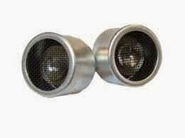
The proposed ultrasonic remote control circuit uses ultrasonic transducers to produce and receive the ultrasonic signals.
Ultrasonic transducers are used in measuring the distance of an object and various other applications. In this circuit, we use them for a different purpose of making a remote controlled relay.
Receiver Circuit
Transmitter Circuit
This project consists of two parts i.e., ultrasonic transmitter circuit and ultrasonic receiver circuit.
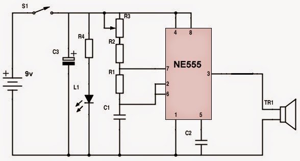
The transmitter circuit consists of a 555 timer IC which is the heart of the circuit. Here, the 555 timer is used in astable multi vibrator mode. It could oscillate at a frequency of 40 - 50 KHz.
The ultrasonic transducer is used to transmit this frequency in the form of ultrasonic waves. A 9v battery can be used to power the transmitter circuit. The variable resistor R3 (in transmitter circuit) can be used to adjust the frequency.
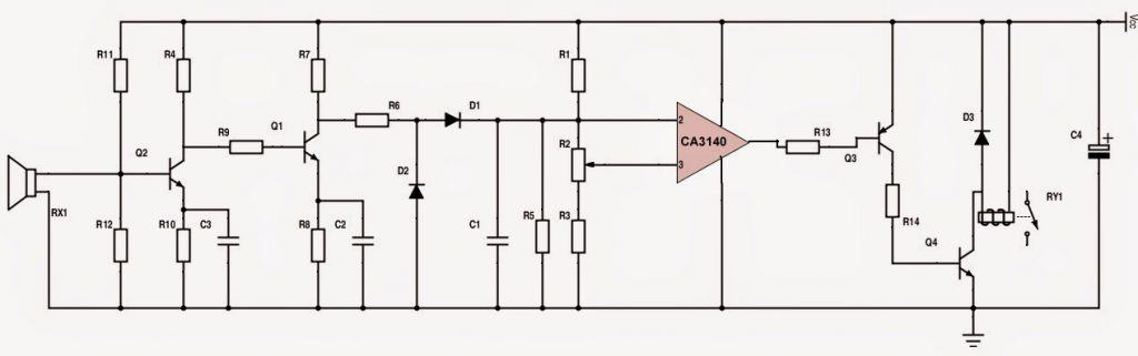
The Receiver Circuit
The receiver circuit consists of two important stages for the processing of the ultrasonic waves received by the receiving transducer.
The first stage is a rectifier which amplifies the signals with the help of the transistors Q1 and Q2.
The rectified and filtered DC is fed to the inverting pin of the operational amplifier CA3140. The inverted output is used to bias the transistor Q3 which energizes the relay and there goes the second stage.
The preset resistor R2( in receiver circuit) can be used to adjust the sensitivity of the circuit.
You can use a 9v SMPS power supply to power the receiver circuit.
The receiver circuit should always remain ON and a push-to-on switch can be used in the transmitting circuit to be used as a remote.
Assemble the circuits on general purpose PCB’s. You can enclose the transmitter circuit in a suitable casing and the transducer, push-to-on switch and LED should be outside of the casing.
Ultrasonic waves are directional in nature and hence, you should direct the waves straight onto the receiving transducer for the relay to activate.
Parts List
- Transmitter circuit:
- R1 – 18K,
- R2 – 10K,
- R3 – 5K variable resistor,
- R4 – 1K,
- C1 – 680pf,
- C2 – 0.01µf,
- C3 – 100µf, 25v,
- L1 – green LED,
- TR1 – ultrasonic transmitter,
- S1 – push-to-on switch,
- Receiver circuit:
- R1 – 10K,
- R2 – 5K variable resistor,
- R3- 10K,
- R4 – 15K,
- R5 – 100K,
- R6 – 10K,
- R7 – 4.7K,
- R8 – 15K,
- R9 – 10K,
- R10 – 12K,
- R11 – 390K,
- R12 – 470K,
- R13 – 27K,
- R14 – 1K,
- C1 – 0.56µf,
- C2 – 0.1µf,
- C3 – 0.22µf,
- C4 – 10µf, 25v,
- D1, D2 – 1N4148,
- D3 – 1N4007,
- Q1, Q2 – BC 548,
- Q3 – BC 558,
- Q4 – SL 100,
- RY1 – 9v relay,
- RX1 – ultrasonic transmitter.


Questions & Answers
hi, i have a similar project. in my aplication: i would like to build a gate (multiple 40Khz ultrasonic speakers attached to a pole, facing one direction. The user has a watch like device with an ultrasonic receiver. When crossing the gate, the “watch” should detect the 40Khz sound and save a timestamp.
So what i need is basically an “is 40khz sound present or not” module.
I have looked up aliexpress for cheap modules but i only found those prebuilt ranging modules, or the simple receiver that still needs to be amplified and filtered.
I have found a quite good solution i guess: TCT40 receiver, LMC567 as filter and the one that makes the triger, MCP6001 for amplifier.
Tho i have no experience with planning a pcb or putting together parts. I have some experience tinkering with ready made modules tho, so would not be a problem to connect them to Arduino or Esp32. But before i would ask someone to design me a pcb and let it manufacture, i would prefer to try a similar module to see if my idea is even working.
do you know if any this kind of remote switch is existing? what is the required voltage on your receiver side? as i saw, your project is fairly similar to my idea, can you explain a bit why did you select the components you selected?
thank you!
Hi, thanks for the detailed specifications!
Yes, your design looks perfectly feasible, however for a PCB you will need to contact a professional PCB designer or a manufacturer.
You can refer to the following article for getting more innovative ideas for your application
https://www.homemade-circuits.com/best-ultrasonic-transmitter-receiver-circuits-for-all-hobbyists/
Since all these circuits were not designed by me, it can be difficult for me to describe the working of each and every part in the circuits.
If you have any specific questions please feel free to ask…
Thanks a lot for the nice article. i think the LM567 based vircuit is what i want to build. Do you think LM567 and LMC567 are interchangeable? i know that the LMC is a newer version of the original LM and it requires lover voltage but also more power efficient… My aplication also requires 3.3v or less…
You are right…The key difference is that the LMC567 is a low-power, CMOS version of the industry-standard LM567, offering reduced power consumption and also maintaining functional similarity. This makes the LMC567 a more power-efficient alternative.
Hi!
What in your experience os the maximum distance for the receiver to “hear” the transmitter? What type are the piezo transducer you have used?
Distance can be around 10 meters. Transducers are 40 kHz ultrasonic as shown in the article…
Thanks!
Is there a way to increase The max. distance? For example different frequency, more decibelsor different transducers? I’m planning to use a 12V battery pack for the project.
I don’t think there’s an alternative way to increase the range of the circuit. 10 meters should be the maximum range.
Thank you!
Is it possible to make a circuit that would enable working distance of 15-20 m or more while using max 12V/20 Ah power supply? (four Li-Ion or Li-Po cells as power pack. Voltage would be lowered to 3,3-12 V depending on other part’s requirements in the system) What would be about the required power when sending/receiving?
Sorry, I have no idea how to modify the range of the circuit. However I have a few interesting ultrasonic circuits published in this blog which you can build and experiment to check if the range increases:
https://www.homemade-circuits.com/best-ultrasonic-transmitter-receiver-circuits-for-all-hobbyists/
Hi I want to design remote which have 2 buttons on the remote control one forward and one for reverse when i press forward button receiver circuit has motor which goes forward and when i press reverse button reciiver circuit reverse the motor how to apply this logic some hint for the logic is ok too thanks in advance
Hi, you can buy readymade 433 Mhz remote control units cheaply from the market…making it can be very difficult.
Thank you Sir for all these precious knowledge & sharing ????⭐????
My pleasure Vikash!
Nice very good for all Diagram I need
1Diagram so possible
Hi, I was taking a look at this circuit.. I am trying to make a similar remote, which has to be ultrasonic, as it needs to pass through the lining of a tent, an IR will not work.
https://www.homemade-circuits.com/ultrasonic-remote-control-circuit/
I have a fishing alarm, which when activated, turns on a lamp inside my tent using a LM555, giving me time to put a light source on. Would the ultrasonic receivers pick up a beep alarm? or would i need to trigger the remote with a MIC and then using your receiver above with an LM555 to a relay switch.
From where the beep will be generated and how the ultrasonic is supposed to pick it up, please explain with more details?
I would like to create an ac low voltage using a homemade transformer by sending a pwm signal to a transistor or f.e.t. and increasing the signal to the base or gate of the transistor or f.e.t. and therefore increasing the voltage. Is it possible? Thanks in advance.