In this post I have explained a simple IC 555 based PWM controller circuit which may be used for controlling the intensity of a specified LED bank or an 12V LED strip light. The idea was requested by Mr. Rajdeep.
Technical Specifications
Fantastic blog you have got. I learnt many things from your blog.
I have read that dimming LEDs by reducing voltage or current lowers the LED lifespan. Is it correct? And the best way to dim LED is by PWM?
I did some more research on this matter and found out that LEDs don't get damaged, but the colour spectrum of LEDs changes at lower current/voltage.
A 6500K LED will move towards 5000K when dimmed, I found this information on some aquarium forum, I can send you the link if you need. Also, they say LED tends to heatup when current-dimmed.
Anyway, can you do a tutorial on pwm of high power LEDs. I have been searching for a tutorial, but could not find any suitable MOSFETs that will work in 5volt, while carrying 20-30amps.
Can such huge load be controlled by a 555-pwm?
Another question, will a pwm circuit work with a 'LM317 constant current circuit'?
P.S: I am planning to do a full LED aquarium lighting, so I am making sure it will work. Sorry for a lot of questions, I am not an electrical engineer, so I need your help. Sorry for bothering you... 🙂
And will pwm work in series with a 317-constant current driver circuit?
If this works, I am thinking the circuit will be like this:
12V smps --> 555pwm --> 317 current limiter --> LED
Rajdeep.
Solving the Circuit Query
Thanks Rajdeep! What you have learned from the forums could be completely incorrect and misleading, LEDs work most efficiently when driven with minimal currents, although that would mean proportionately lower intensity.
Driving an LED through PWM actually is not difficult....higher duty cycle will produce higher intensity and vice versa, that's the basic principle behind it.
The Design
First I have explained about a 12V PWM LED light controller circuit, later at the concluding section of the article we'll see how the same may be implemented using 5V supply and a mosfet.
The following circuit idea shows a simple PWM controller circuit using IC 555 which can be used for controlling or dimming ready made commercial 12V LED strip lights. The dimming control can be right from 0 to maximum.
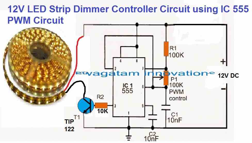
You can also build your own high power LED strip lighting for home lighting by configuring series parallel LEDs, and then you can implement the dimming effect on these LEDs using the following circuit.
The MOSFET can be an IRF540 MOSFET
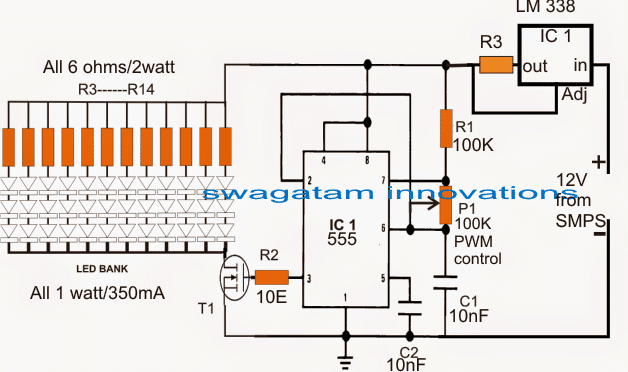
In the image above, the supply is acquired from an SMPS unit which applied to the PWM circuit through a LM338 current controller circuit stage.
The pot P1 is used for adjusting the PWM duty cycles to the LED bank for achieving the desired intensity levels.
The resistor R3 determines the limiting current level from the IC LM338, it may be calculated with the following formula:
R3 = 1.25/LED current
The circuit shows a 36 LED (1 watt each) light strip bank being driven by the PWM and the current controller stages.
The LED series resistors are introduced for safeguarding each 3 LED string from over voltage. since the total forward voltage drop of the strings constitute to 3.3 x 3 = 9.9V and the supply voltage 12V that's about 2V higher.
R3 controls the overall current for the entire LED bank, and may be calculated by using the above mentioned formula, for the shown design the result may be calculated as:
R3 = 1.25/0.35 x 12 = 0.29 Ohms
Wattage = 1.25 x 0.35 x 12 = 5.25 watts, here 0.35 is the current through each LED string, 12 is the number of strings, and 1.25 is the fixed reference as specified by the IC LM338 datasheet.
With a little effort you can skip the LM338 stage by modifying your existing SMPS unit to any desired maximum current limit, as per the specs of the LED, the entire procedure may be learned below:
How to make a variable current SMPS circuit
Using PWM Control from 5V source
In cases where the supply voltage is restricted to 5V, and the intended applications requires a PWM dimming control of 12V LED bank or strips through a mosfet, the following circuit can be suitably used for the same.
Circuit Diagram
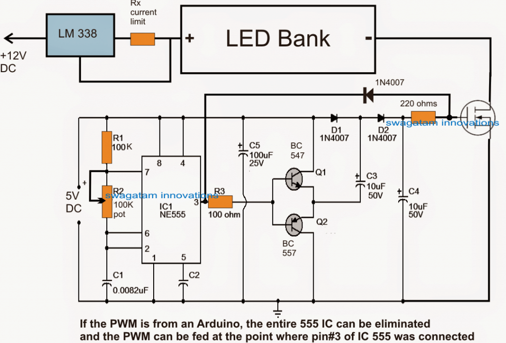
As we can see, the above configuration is identical to the first one, barring the addition of the voltage booster stage between pin3 of the IC 555 and the mosfet gate.
Here a couple of diodes and capacitors effectively raise the pin3 PWM level from 5V peak to 10V peak, this becomes imperative since a mosfet is being used for the regulations, and mosfets do not respond optimally with gate voltages lower than 9V.
The shown mosfet gate voltage booster stage can be also applied with PWM outputs that may be derived from an Arduino board or other MCUs.


Comments
Greetings..
Dear Swagatam,
I assembled the circuit with tip122 and 555ic but when varying the 100k pot meter the led didnot turnoff completely. Only a small variation is only possible.The base resistor to tip122 is 10k but other circuits its 10ohm.I think its ok.But can’t vary the led brightness from zero to 100 percent.please help me.
Thank you Dr.Sison, for updating the results,
Yes, the above design will not give you 100% PWM control. To get around 99% PWM control, you can try the following concept, The base resistor cannot be 10 ohm for any TIP122, you might have seen a MOSFET not a BJT. 10k is OK, or you can also reduce it to 1k for maximum brightness on the LEDs, depending on the LED specs.
https://www.homemade-circuits.com/wp-content/uploads/2012/05/batterydesulfatorcircuit.png
Thank you Dear Swagatam. But if i use12volt supply voltage(in the sche its15v)and instead of mosfet use TIP122 what modification is required ? Already purchased 100k pot can i use the same on updated circuit?expecting your reply. Thank you so much.
Dear Dr.Sison,
You can try with 100k pot and see how it works, and also increase the top 1k value to 10k in the attached circuit diagram.
Make sure the TIP122 base resistor is higher than 1k.
Greetings
Dear Swagatam,
The same circuit diagram with 1k and with 100k pot meter works fine morover the value of base resistance is 10k for optimum performance. Im doing this on my new fish tank light to control the intensity also for increase the longivity of led .I incorporate the current control feature with 7812.It was really amazing circuit .tons of thanks to Swagatam for providing such great solution for our day today problems…❤❤❤❤🤝🤝🤝🤝❤❤❤❤❤
That’s great Dr.Sison,
I am glad it is working as per your expectations now.
All the best to you.
Please keep up the good work!
Thank you anyway i will try and update you soon.
Hi Swagata,
Can this circuit control a LED COB of 12V 200W?
Thanks.
Best Regards.
Nelio.
Hi Nelio,
Yes, the circuit can be used universally with all types of LEDs.
In the fisrt diagram, are all three pins of the potentiometer connected ? The arrowhead near the potentiometer is a bit confusing for me.
thanks!
The pot has 3 pins, the center pin and one of the outer pins is connected with pin2 and pin6. The other outer pin is connected to pin7 and R1
Spect.le It is possible to have an automatic fade in/out circuit
Thank you
Best regards
Gabriele Febbo
Fade in may be possible by increasing the C2 value 220uF or something bigger. However I don’t think fade out could be possible using this circuit.
Hello Sir, Good afternoon ,Really you have taught us in a very easy way and I have a doubt ,can we use this transistor based amplification for pwm derived from capacitor touch dimmer sensor and further can we use TIP 122 for driving led bank instead of a Mosfet. My PWM touch dimmer sensor runs on 5v supply.
Thank you Bharat, Glad you found the post useful. yes you can use the transistor stage and feed it from an external PWM source for controlling the LEDs. TIP122 also can be used instead of a mosfet.
Hi Swag,
I just came across your website you are great.
What is the best way to dim common 12V LED lights commonly available in the market. I mean the MR 16 type which has an internal driver. My board is powered by 12 Volts DC. PWM is not giving me a good dimming range. Thanks and regards
Kazem
Thank you Kazem, PWM will not help because of the internal filter capacitor after the bridge circuit. You can try removing the filter capacitor and then try the PWM, as explained in the following article:
How to Add a Dimmer Facility to a LED Bulb
Hi, Swag thanks for the quick reply. Unfortunately, it is not possible to modify the light bulbs. Is there any way to dim the bulbs without any modifications? Best regards
Kazem
Hi, Kazem, according to me it seems impossible to dim an LED bulb externally, without opening it.
Good day Swag, please I need a DC dimmer for input of 96v, 10amps. Thanks.
Seun, you can use the 1st circuit, wit the LED side positive connected with the 96V input.
I’m looking for some help identifying some smd components in a 12VDC LED circuit. its from a BMW tail light. It has dimmable LEDs. I have a picture of the item, although I can’t upload that to here. any help would be great thanks as id like to fix it. It has stopped working, LED are extremely dim.
You can upload the pic on any free image hosting site and provide the link here, I will try to figure it out.
Sir, can I run a pwm circuit on mobile battery 3.7v??
Any cheap solution?
Nitin, the IC 555 will not work correctly with 3.7V, you can try the following circuit instead:
https://www.homemade-circuits.com/how-to-make-any-light-strobe-light/
Hi, this helped a lot, thanks for sharing. Is there any post that talks about PWM using arduino for controlling AC power (using fast switching device/IGBT)? The explanation of arduino programming for this concept would be very useful for students like us. Thanks again and we hope for such project from swagatam.
Hi, I am glad it helped you, I have one Arduino based circuit which you can find below, hope this one fulfills your requirement
https://www.homemade-circuits.com/arduino-pwm-signal-generator/
https://www.homemade-circuits.com/high-current-motor-control-using-arduino/
Hello Swagatam Majumdar, i saw your circuit project and i was thinking of using you project to create an LED lamp. I just want to ask is it possible to increase the number of columns from 12 to 20? Also how can i choose the value of T1? Thank you in advance..
Thanks for liking my articles, A plasma screen is supposed to be working with an SMPS supply, so I am not sure how you would be associating the above circuit with your plasma screen, since the circuitry of the screen would be extremely complex and sophisticated…I wouldn't recommend doing any kind of modifications to it..
Hi swagatam i love your article am having a problem with my lg plasma tv it screen lights keep on blicking for every 2sec Can I use this circuit you posted here to control it screen lights
Hello Harimel,
yes you can put as many parallel columns as you may want, simply by adding the required number of LED strings with their specified series resistors, but please make sure that the supply current is also appropriately upgraded for enabling proper illumination on the LEDs.
the mosfet just like the supply specs should match the LED voltage and the current…..preferably it should be twice of the LED series fwd voltage value and the total LED ampere value. Mosfest having higher values than this will have no problems but it should not be lower than the LeD power specs.
I want to drive some 5W leds using PWM using above circuit.
The specs for led are:
Vf= 9-12V
If= 750mA
What changes should be made to the above circuit for the leds with above specs.
Also I'll be making three drivers,one for the above led ones and other two for led banks with 3.0-3.4V,750mA and other led bank with 3.0v-3.2V,350mA.
(I asked you about how to drive the above led banks some days back if you remember.But since I'll be using them i aquarium,I need to control brightness too so decided PWM method.)
I'll be highly grateful to you if you tell me the changes to be made in the above circuit to drive 3 led banks separately.
(Please edit the following part as these are my contacts.)
You can even E-mail me on akp.ajinkya@gmail.com or whatsapp me on 9634943246,so that I can discuss with you.
you can try it, if it works then the problem is in your 2N2222 transistor…make sure to use a low value resistor at the base….you can calculate it using the following formula
R = (supply V – 0.7) x 30 divided by LED current
Oh..yeah,I can understand about the whatsapp issue.
The 2n3055 remains at room temperature 'cause the ckt isnt drawing much current(only about 600-800 mA).Should I go ahead and try 2n3055 directly fed with pwm output?
but if the LEDs are working without the PWM circuit then the SMPS cannot be the issue. Is your 2N3055 heating up a lot? this transistor could be the culprit and causing insufficient current for the LEDs.
sorry bro whatsapp will not be possible because I have 100s of readers and all might start requesting this facility…so it won't be possible.
Are you on whatsapp bro?
Don't know why the configuration didn't work,I tried the same ckt with a single 10W led,it worked good(although with a smps based 12v,2A adapter),seems like smps is limiting supply current.
without 2N2222 attached or without a Darlington configuration, the gain could be 1000 times less…still you can try that
May be you did not make the Darlington correctly, or may be one of the transistor is faulty, otherwise it's impossible…. because in the Darlingtom mode the current gain should be extremely high making the LEDs almost fully bright, when the PWM is set at the full width.
make sure the average voltage at pin#3 is almost equal to the supply when the PWM is maximum or if this is not happening then it's the fault of the PWM generation
Tried the circuit from the link you gave above with a darlington pair of 2n2222 and 2n3055,but leds doesn't attain their full brightness,the dimming action is there but they just don't light up like when i power them directly.I am powering the circuit using a hacked pc smps and all leds are connected in parallel.I also tried powering 555 ckt using another supply and transistor-bypass ckt(2n3055) using the pc smps for led but to no avail.
Should I try directly connecting pwm output of 555 to 2n3055(i.e without 2n2222 in between)?
Many thanks bro..will try it.Will contact again if i have some doubt 🙂
for 10 amp you can try a 2N3055 transistor with a 2N2222 to form a Darlington pair.
a mosfet can work but its full gate supply will need to be 5V higher than the LED operating voltage for getting maximum illumination.
same supply can be used for the LeD and the circuit
Took a look at the circuit,seems like transistor can only handle current about 5A,but i'd be requiring more than 10A to drive them…i.e will be using 14 of the above said leds of 5w so 750×14=10.5A….is that correct?
So Which transistor or mosfet can i use for such high current?
Also I'll be driving the led and circuit from a pc smps(a hacked one) with 24A on 12V rail.Also would it be a good idea to drive both led bank and 555 ckt with the same supply i.e pc smps.
Apologies for asking too many questions.
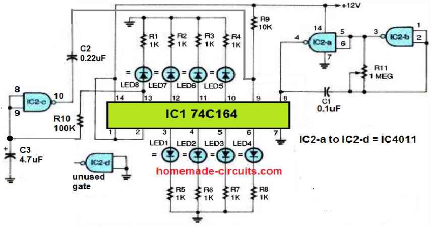
You can make the following design which looks more effective than the above
https://www.homemade-circuits.com/2014/11/150-led-pwm-tubelight-circuit.html
the circuit parts will remain as is, only the LED series resistors will need to be calculated and positioned as per the LED specs.
Hello Swagatam Sir,
I am a beginner and hobbyist and i wanted to ask you a general question regarding schematics and circuits design diagrams .I have seen many electronics schematics across the web and find that the voltage of capacitor (polarized and non-polarized)and watt of resistor are not mentioned i.e. C1 0.0082uf and R1 100K . Is there any general rule of thumb for this kind of values? If we do not know the exact values then will it be very difficult to purchase such parts and one could face difficulty in simulation(because simulators does required the value of volt and watt). The exact value may be required for other components also.Sir please sort out my problem.
Hello Rohit,
all resistors which are unspecified can be assumed to be 1/4 watt by default.
all capacitors which are non-electrolytic are mostly available with 50V rating in the market, therefore mentioning the voltage rating for these caps is normally ignored since it's already well above the safe level….however if the circuit's supply voltage is above 40V then it must be appropriately upgraded, and needs to be specified.
electrolytic capacitor voltages must be preferably rated at twice the supply voltage
the specs for other parts can be acquired from their respective datasheets.
I have modified the second circuit, you can check it now.
ULN2003 have Darlington transistor arrays, so each input/output set will work exactly as a Darlington transistor configuration would work
At the first 10uF capacitor, the pwm voltage range drops to from 0-5V (from arduino) to 2-3V (at multimeter).
I tried running the MOSFET with a bc547, it seems the maximum voltage that can be obtained is ~9V at the LED due to loss at the LM317, bc547, IRF540. So, I am thinking of using simple relays instead of this circuit, as there is a lot of complexity, cost, voltage drop in the system.
BTW, the bc547 was very hot when running the MOSFET.
Now I am thinking of a relay circuit through ULN2003.
Does ULN2003 inverts the signal?
Can a relay support 20A current?
did you check the voltages at the various and did you try to find why it's not working?
first try without the voltage booster…
This circuit doesnot work, I tried It out today.