In this post I have explained a simple IC 555 based PWM controller circuit which may be used for controlling the intensity of a specified LED bank or an 12V LED strip light. The idea was requested by Mr. Rajdeep.
Technical Specifications
Fantastic blog you have got. I learnt many things from your blog.
I have read that dimming LEDs by reducing voltage or current lowers the LED lifespan. Is it correct? And the best way to dim LED is by PWM?
I did some more research on this matter and found out that LEDs don't get damaged, but the colour spectrum of LEDs changes at lower current/voltage.
A 6500K LED will move towards 5000K when dimmed, I found this information on some aquarium forum, I can send you the link if you need. Also, they say LED tends to heatup when current-dimmed.
Anyway, can you do a tutorial on pwm of high power LEDs. I have been searching for a tutorial, but could not find any suitable MOSFETs that will work in 5volt, while carrying 20-30amps.
Can such huge load be controlled by a 555-pwm?
Another question, will a pwm circuit work with a 'LM317 constant current circuit'?
P.S: I am planning to do a full LED aquarium lighting, so I am making sure it will work. Sorry for a lot of questions, I am not an electrical engineer, so I need your help. Sorry for bothering you... 🙂
And will pwm work in series with a 317-constant current driver circuit?
If this works, I am thinking the circuit will be like this:
12V smps --> 555pwm --> 317 current limiter --> LED
Rajdeep.
Solving the Circuit Query
Thanks Rajdeep! What you have learned from the forums could be completely incorrect and misleading, LEDs work most efficiently when driven with minimal currents, although that would mean proportionately lower intensity.
Driving an LED through PWM actually is not difficult....higher duty cycle will produce higher intensity and vice versa, that's the basic principle behind it.
The Design
First I have explained about a 12V PWM LED light controller circuit, later at the concluding section of the article we'll see how the same may be implemented using 5V supply and a mosfet.
The following circuit idea shows a simple PWM controller circuit using IC 555 which can be used for controlling or dimming ready made commercial 12V LED strip lights. The dimming control can be right from 0 to maximum.
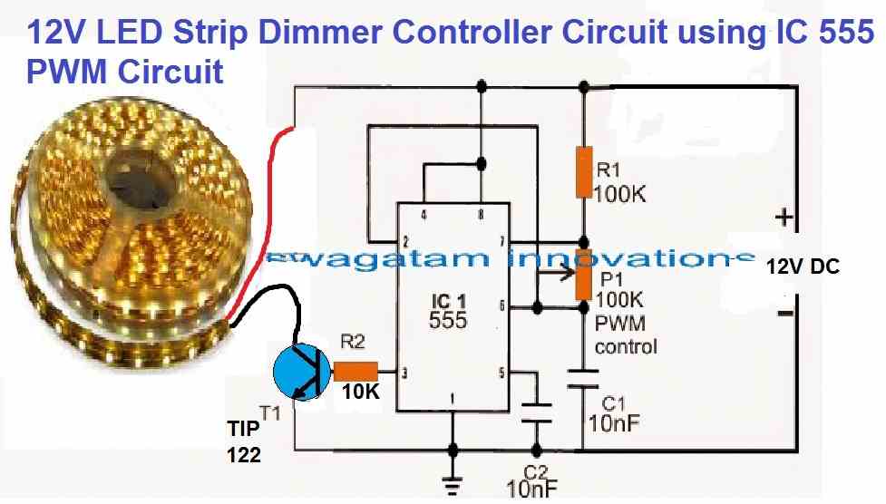
You can also build your own high power LED strip lighting for home lighting by configuring series parallel LEDs, and then you can implement the dimming effect on these LEDs using the following circuit.
The MOSFET can be an IRF540 MOSFET
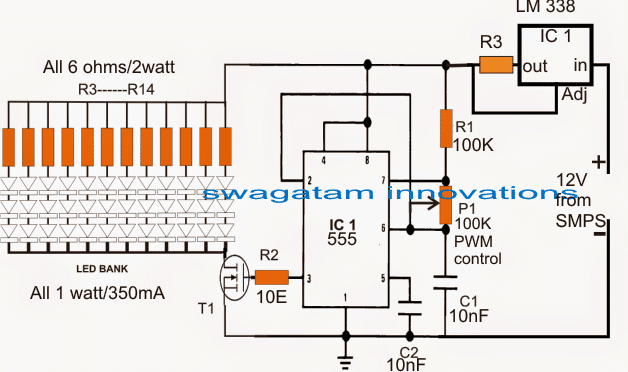
In the image above, the supply is acquired from an SMPS unit which applied to the PWM circuit through a LM338 current controller circuit stage.
The pot P1 is used for adjusting the PWM duty cycles to the LED bank for achieving the desired intensity levels.
The resistor R3 determines the limiting current level from the IC LM338, it may be calculated with the following formula:
R3 = 1.25/LED current
The circuit shows a 36 LED (1 watt each) light strip bank being driven by the PWM and the current controller stages.
The LED series resistors are introduced for safeguarding each 3 LED string from over voltage. since the total forward voltage drop of the strings constitute to 3.3 x 3 = 9.9V and the supply voltage 12V that's about 2V higher.
R3 controls the overall current for the entire LED bank, and may be calculated by using the above mentioned formula, for the shown design the result may be calculated as:
R3 = 1.25/0.35 x 12 = 0.29 Ohms
Wattage = 1.25 x 0.35 x 12 = 5.25 watts, here 0.35 is the current through each LED string, 12 is the number of strings, and 1.25 is the fixed reference as specified by the IC LM338 datasheet.
With a little effort you can skip the LM338 stage by modifying your existing SMPS unit to any desired maximum current limit, as per the specs of the LED, the entire procedure may be learned below:
How to make a variable current SMPS circuit
Using PWM Control from 5V source
In cases where the supply voltage is restricted to 5V, and the intended applications requires a PWM dimming control of 12V LED bank or strips through a mosfet, the following circuit can be suitably used for the same.
Circuit Diagram
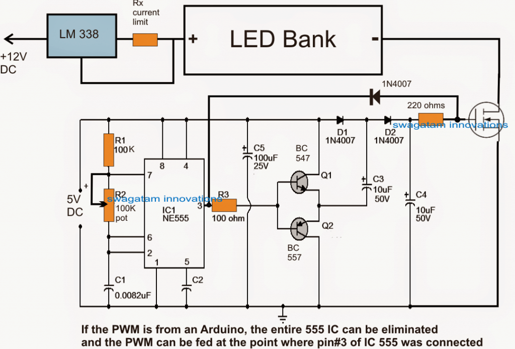
As we can see, the above configuration is identical to the first one, barring the addition of the voltage booster stage between pin3 of the IC 555 and the mosfet gate.
Here a couple of diodes and capacitors effectively raise the pin3 PWM level from 5V peak to 10V peak, this becomes imperative since a mosfet is being used for the regulations, and mosfets do not respond optimally with gate voltages lower than 9V.
The shown mosfet gate voltage booster stage can be also applied with PWM outputs that may be derived from an Arduino board or other MCUs.


Comments
should not 555 be driven with a supply greater than 5v to operate
4.5V is the minimum limit….
Will this circuit work?
s18.postimg.org/y8l1m6sp5/5_V_pwm_led_circuit.jpg
Sorry, I had to edit your picture.
IRF540 has a gate voltage of 20 V, will it run on this circuit?
when you said "IRF540 has a gate voltage of 20 V, will it run on this circuit" I misunderstood it and thought that you are asking if 20V could be used at the gate….My above question was in response to this
yes 5V when raised to 10V will be fine for the mosfet
Yes, 5V comes from an arduino data pin.
You wrote, "Here a couple diodes and capacitors effectively raise the pin3 PWM level from 5V peak to 10V peak"; so my circuit should work with a 12 V supply…
20 V is too high, it must be blow 15V and above 10V.
your image shows 5V as the gate drive?
Thank you very much for this article.
What is the transistor 'T1'?
And is the value of R2 = 10 ohm?
I wanted to control 10Watt LEDs, which are 12V, ~1A. What should I change as per the first circuit? Haw many 10W LEDs can be controlled with a single 555?
you can as many as you want just by upgrading the power of T1….for example with an IRF540 you would be able to use as many as 150 LEDs in parallel
T1 can be any suitable mosfet rated at above the voltage and current ratings of the LED bank