The main feature of this lambda-diode low battery indicator for Ni-Cd batteries is that, the circuit itself consumes almost zero current, until the set low threshold level is reached and the indicator LED is illuminated.
This feature makes the circuit very suitable for many low voltage battery operated systems, like radios, watches, timers, alarms, remote controls etc.
The primary reason of premature cell damage in nickel-cadmium batteries is their internal shorting that happens due to the the battery getting far too deeply discharged while operating.
Hence, any electronic gadget using Ni-Cd cells must include a low-battery indicator which can trigger and alert the user to recharge it, well before the battery's "critical" voltage is reached.
Although you will find many kinds of charge monitors that could be integrated inside your battery-powered products, the lambda-diode monitor I have explained in this article is perhaps a more sophisticated option than any other battery monitors available.
Better than other Low Battery Indicator Systems
Most low-battery indicators work with BJTs to toggle on the LED drive current or for a meter display. The disadvantage in such designs is that the circuit continuously drain the battery, even while the LED is in the shut off state.
In low-power circuits, this kind of battery drain could dramatically affect and reduce the back up time of the battery.
The best remedy to solve this is to use a circuit that consumes absolutely no current from the battery, so long as the supply voltage is higher than the battery's critical potential.
This is exactly what the lambda-diode based low battery monitor executes.
It also features an adjustable trigger threshold across a voltage range of 8-to-20 V, and it could be built quite cheaply.
Ni-Cd Charge/Discharge Characteristic
The terminal voltage of all batteries varies depending on their state of charge. This characteristic of this relationship may be different for different batteries .
For example with Lead-acid batteries, we find practically a very linear drop in their output voltage as the cells are discharged. This behavior is typically the same for dry cells also.
But, for Ni-Cd batteries, the voltage drop while discharging is not very linear. A totally charged Ni-Cd cell may exhibit an output voltage of approximately 1.25 volts.
This level is maintained fairly constantly until it is pretty-much fully discharged. At this point the cell voltage drops rapidly to approximately 1.0 to 1.1 volts, or 1.05 V.
An accurate voltage monitor circuit adjusted to activate at this "critical" voltage level can be extremely helpful in identifying the charge level of the Ni-Cd battery.
An eight-cell Ni-Cd battery pack, for instance, could have a fully charged output potential of 10.0 volts. When it is almost fully discharged, the battery might have an output of 8.4 volts.
How Lambda-Diode Low Battery Indicator Works
The lambda-diode low battery monitor circuit as shown in the following figure is adjusted to activate at 8.4 volts, which enables us to achieve an effective state-of-charge (SoC) monitor system for a Ni-Cd battery.
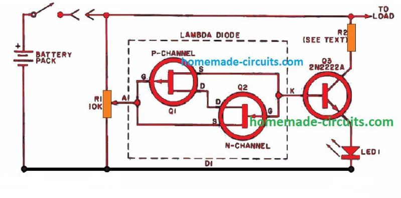
The lambda diode represented inside the dashed box is built using a pair of n- and p-channel FET's.
Remember that there's no ready made "lambda" diode available in the market.
Practically, a lambda diode is built by interconnecting two low power FETs, and is operated using only two terminals, marked "anode" (A) and "cathode" (K).
When the biasing over this lambda diode is in the cut off mode, transistor Q3 is also switched off, which in turn keeps the LED1 is off.
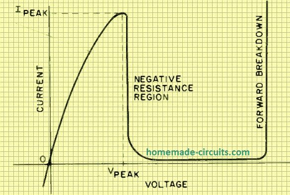
As the battery voltage begins falling, it reaches a point where the lambda diode suddenly gets biased and conducts.
This situation instantly biases Q3 into conduction which powers ON the LED alerting the user regarding the low-battery condition. (The working characteristic of the lambda diode can be witnessed below).
The potential level which biases the lambda diode into conduction is totally adjustable through the potentiometer R1.
Resistor R2 is wired like a current limiter for safeguarding LED1. The value of this current limiting resistors can be calculated using Ohm's Law (R2 = E/I, where R2 is in ohms, E represents the Ni-Cd battery potential threshold where the LED1 just illuminates, and I should be replaced with the maximum safe current value for the LED.
Construction Details
The above explained lambda-diode battery-charge monitor is quite compact to be accommodated into the gear where a Ni-Cd battery pack is utilized as the power source.
Additionally, it could be constructed and applied externally as a low -battery indicator equipment and encased within a small box. In both the cases, a PCB can be used as shown below.
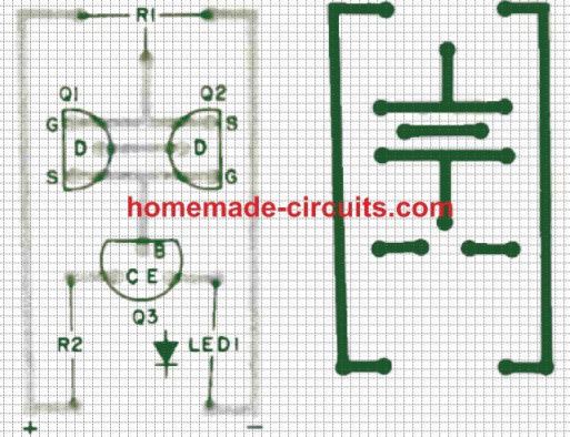
The JFET type for building the lambda diode is actually not critical. Nearly all configurations involving n- and p -channel FETs should perform well, along with the ones that are specified in the parts list.
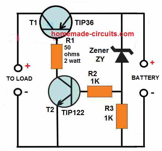
If required you can consider replacing the LED1 with a low power relay to enable disconnection of the Ni-Cad battery pack from the load as soon as the voltage level drops below the critical low threshold. This particular arrangement will automatically safeguard the battery pack from polarity reversal while it is being discharged.
Parts List
LED1 - Any 5mm 20 mA LED
Q1 - P-channel JFET (2N4360 or similar)
Q2 - N-channel JFET (2N3819 or similar)
Q3 - NPN BJT 2N2222A or similar
R1 -10 k, preset
R2 - Current-limiting resistor (see text) can be a 150 ohms 1/2 -watt


Comments
I love the elegance of this circuit. I would like to use it to shut off a battery to protect it when the terminal voltage is reached. What sort of latching relay (I don’t know what to look for) would you suggest and what does the circuit look like for it?
Thanks, love you content!
Glad you liked the circuit, are you looking for an over voltage cut off circuit?
In that case you can try the designs explained in the following post. A relay may not be recommended since 3 V relays are not commonly available in the market an might consume a lot of current.
The last design has both, over charge and over discharge protections.
https://www.homemade-circuits.com/battery-deep-discharge-protection-circuit/
Hi, yes for some applications you need to match the parameters.
I found that PH3820 works better at low voltages (cough EW /cough) but others work better at high voltages. Something about a secondary valley but its fascinating.
I also found that the N channel units found in old electrets work well though tend to be electrically more delicate. SMDs even more so!
Very nice topic, the best the consumption comparative Issue. I like the topic. Do I need tom pair the FET in Hfe or just any can be used?
Thank you!
Glad you liked it, no need of matching their specs, you can use any N, and P channel JFET combination.