• Skip to primary navigation
  • Skip to main content
  • Skip to primary sidebar

Homemade Circuit Projects

Get free circuit help 24/7

  • 1000+ Circuits
  • Privacy Policy
  • About Us
  • Contact
  • Disclaimer
  • Videos – Circuit Test Results
You are here: Home / Simple Circuits / Simple Touch Operated Potentiometer Circuit

Simple Touch Operated Potentiometer Circuit

Last Updated on May 28, 2020 by Matrix 2 Comments

In this touch operated potentiometer circuit we have two touch pads, which produce a slowly increasing voltage at the output when one touch pad is touched, and a decreasing voltage when the other touch pad is touched.

When the touch contact is removed the voltage holds at that particular increased or decreased level "permanently".

Touch pad switches typically work by incorporating a basic digital memory system. However these could be also operated to allow an analogue output voltage as in this article through a low cost circuit which is simple to construct.

Circuit Description

The circuit is centered around the IC1, an op amp having a extremely high input impedance, that is configured as an integrator.

When touch-pad TP1 is touched with a finger, capacitor C2, an MKT type low leakage capacitor charges through the resistances of the skin, which triggers the output voltage of IC1 to decrease linearly to zero.

If the second touch-pad, TP2, is touched, results in an opposite response. Now, the voltage output of IC1 increases linearly to a level that's equal to the supply voltage.

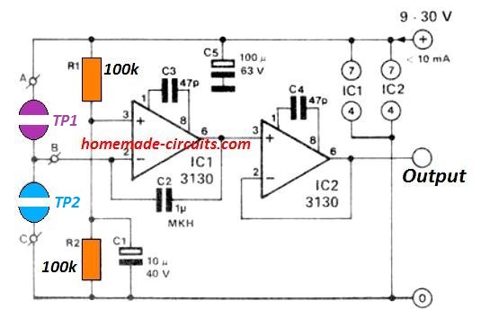
The best feature of this touch operated potentiometer circuit is that as soon as the finger contact is removed from the pad, the voltage magnitude then appearing at the output of IC1 is retained by the stored charge on C2.

On account of inevitable leakage currents in the capacitor, the output voltage will, eventually, start drifting by approximately 2 % each hour towards zero or towards the supply voltage, depending on which specific key pad had been touched last.

To ensure that the leakage current is as minimum as possible, it is important to keep the circuit away from humidity or dampness. This is a crucial aspect that must be taken into account while implementing this design.

Applications

The applications possibility for this of this solid state touch pad potentiometer circuit can be extensive: it could be used just about anywhere that requires a potentiometer for generating a touch operated variable voltage.

If you want to employ standard push button switches as an alternative to touch pad, the following figure explains how this could be implemented by substituting the touch pad points.

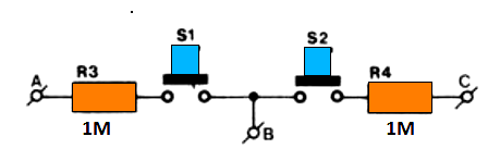
Resistors R3 and R4 imitate the skin resistance; switches S1 and S2 supply the input potential to the IC1.

If you press the two switches together the output will stay unaffected and won't produce any variation in its existing value. Capacitors C3 and C4 eliminate all possibility of the operational amplifier to go into an oscillation mode.


Previous: Digital Theremin Circuit – Make Music with your Hands
Next: Laboratory Power Supply Circuit

About Matrix

I am a contributing editor to homemade-circuits.com. Although I am mechanical engineer by profession, my great passion for practical electronics has helped me to learn a lot over the years. I also love answering to forum questions, and am always happy to help in this amazing field of electronics.

You'll also like:

  • 1.  Simple Adjustable Industrial Timer Circuit
  • 2.  Simplest Windmill Generator Circuit
  • 3.  Simple Shadow Sensor Alarm Circuit
  • 4.  Simple Kitchen Timer Circuit – Egg Timer
  • 5.  Simple Musical Door Bell Circuit
  • 6.  4 Simple Siren Circuits you can Build at Home

Please Subscribe (Only if you are Genuinely Interested in our Newsletters)


Reader Interactions

Comments

    Your Comments are too Valuable! But please see that they are related to the above article, and are not off-topic! Cancel reply

    Your email address will not be published. Required fields are marked *

  1. Search Related Posts for Commenting

  2. fernando says

    me interesan sus circuitos pero tengo un problema con ssus paginas al llegar ala14 ya no puedo seguir abansando gracias

    Reply
    • Swagatam says

      ¿A qué página 14 te refieres? por favor aclare Muchas gracias por su colaboración.

      Reply


  3. COMMENT BOX IS MOVED AT THE TOP


Primary Sidebar

Electronic Projects Categories

  • 3-Phase Power (15)
  • 324 IC Circuits (19)
  • 4017 IC Circuits (51)
  • 4060 IC Circuits (25)
  • 555 IC Circuits (92)
  • 741 IC Circuits (18)
  • Amplifiers (49)
  • Arduino Engineering Projects (82)
  • Audio Projects (84)
  • Battery Chargers (75)
  • Car and Motorcycle (87)
  • Datasheets (45)
  • Decorative Lighting (Diwali, Christmas) (31)
  • DIY LED Projects (81)
  • Electronic Components (97)
  • Electronic Devices and Circuit Theory (35)
  • Electronics Tutorial (99)
  • Fish Aquarium (5)
  • Free Energy (34)
  • Games (2)
  • GSM Projects (9)
  • Health Related (17)
  • Heater Controllers (23)
  • Home Electrical Circuits (98)
  • Incubator Related (6)
  • Industrial Electronics (26)
  • Infrared (IR) (39)
  • Inverter Circuits (94)
  • Laser Projects (10)
  • LM317/LM338 (21)
  • LM3915 IC (24)
  • Meters and Testers (54)
  • Mini Projects (153)
  • Motor Controller (64)
  • MPPT (7)
  • Oscillator Circuits (12)
  • PIR (Passive Infrared) (8)
  • Power Electronics (33)
  • Power Supply Circuits (66)
  • Radio Circuits (9)
  • Remote Control (46)
  • Security and Alarm (56)
  • Sensors and Detectors (115)
  • SG3525 IC (5)
  • Simple Circuits (72)
  • SMPS (30)
  • Solar Controllers (60)
  • Timer and Delay Relay (51)
  • TL494 IC (5)
  • Transformerless Power Supply (8)
  • Transmitter Circuits (38)
  • Ultrasonic Projects (12)
  • Water Level Controller (45)

Follow Homemade Circuits

Facebook
Twitter
YouTube
Instagram
My Facebook-Page
Quora

Feeds

Post RSS
Comment RSS

Circuit Calculators

  • AWG to Millimeter Converter
  • Battery Back up Time Calculator
  • Capacitance Reactance Calculator
  • IC 555 Astable Calculator
  • IC 555 Monostable Calculator
  • Inductance Calculator
  • LC Resonance Calculator
  • LM317, LM338, LM396 Calculator
  • Ohm’s Law Calculator
  • Phase Angle Phase Shift Calculator
  • Power Factor (PF) Calculator
  • Reactance Calculator
  • Small Signal Transistor(BJT) and Diode Quick Datasheet
  • Transistor Astable Calculator
  • Transistor base Resistor Calculator
  • Voltage Divider Calculator
  • Wire Current Calculator
  • Zener Diode Calculator

© 2021 · Swagatam Innovations