In this post we try to investigate internal resistance of battery and try to learn the critical characteristics involved with this battery parameter.
What's Internal Resistance of Battery
The internal resistance (IR) of a battery is basically the level of opposition to the passage of electrons or current through the battery in a closed loop. There are basically two factors that influence the internal resistance of a particular battery; viz: electronic resistance and ionic resistance. The electronic resistance in conjunction with the ionic resistance is conventionally termed as the total effective resistance
The electronic resistance allows access to the resistivity of the practical components which can include the metallic covers and other relevant associated materials; and also, at what level these materials might be in physical contact across one another.
The result of the above parameters related to the generation of the total effective resistance could be quick, and could be witnessed within the initial few fraction of milliseconds after a battery is subjected under a load.
What is Ionic Resistance
Ionic resistance is the resistance to electron passage within the battery as a result of a multitude of electrochemical parameters which might include, electrolyte conductivity, ion streaming and electrode surface cross section.
Such polarization results initiate rather sluggishly compared to the electronic resistance which add up to the total effective resistance, usually taking place some milliseconds after a battery is influenced under load.
A 1000 Hz impedance test evaluation is often implemented in order to indicate internal resistance. Impedance is referred to as resistance offered to AC passage through a given loop. As a consequence of the relatively high frequency of a 1000 Hz, some degree of the ionic resistance probably might fail to get entirely recorded.
In most cases, the 1000 Hz impedance significance is going to be below the overall effective resistance value for the relevant battery in question. An impedance check across a a selected range of frequencies could be tried to enable an accurate display of the internal resistance.
Effect of ionic Resistance
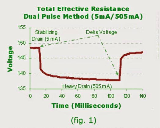
The effect of an electronic and ionic resistance could be identified when the set up is tested with a a double pulse input verification. This test makes use of a procedure of introducing a battery in question on a subdued background drain so that the discharging is first stabilized before pulsing is initiated with a more significant load, for some 100 milliseconds.
Calculating Effective Resistance
With the help of “Ohms Law”, the total effective resistance is easily evaluated by dividing the difference in voltage by the difference current. By referring to the evaluation shown in (fig. 1), with a 5 mA stabilization load in conjunction with a 505 mA pulse, the difference in current is 500 mA. If the voltage deviates from 1.485 to 1.378, the delta voltage could be witnessed as 0.107 Volts, thereby indicating a total effective resistance of 0.107 Volts / 500mA or 0.214 Ohms.
The characteristic effective resistances of brand new Energizer alkaline cylindrical batteries (through a 5 mA stabilization drain and immediately with a 505 mA, 100 millisecond pulse) could be expected to be around 150 to 300 milliohms, as determined by the relative dimension.
What's Flash Amps
Flash amps is additionally Incorporated to induce an approximation of internal resistance. Flash amps are understood to be the maximum current a battery may be expected to supply for a significantly shorter time.
This test is sometimes carried out by electrically shorting a battery with a 0.01 ohm resistor for somewhere within 0.2 seconds and recording the closed circuit voltage. The current circulation via the resistor could be determined by means of Ohms Law and dividing the closed circuit voltage by 0.01 ohms.
The open circuit voltage before the the test is divided by the flash amps to attain an approximation of internal resistance.
Considering Flash Amps could not be easy to perfectly determine and OCV, could be calculated on numerous conditions, this way of measuring needs to only be applied to achieve a generic approximation of internal resistance.
The voltage drop of a battery under load may be relative to total effective resistance along with current drain rate.
General information of initial voltage drop under load are typically estimated by multiplying the total effective resistance by the current drain subjected the battery.
Let's say a battery with an internal resistance of 0.1 ohms is discharged or drained at 1 amp rate.
Then as per Ohms law:
V = I x R = 1 x 0.1 = 0.1 Volts
If we consider the open circuit voltage to be 1.6V, then the expected closed circuit voltage of the battrey could be written as:
1.6 - 0.1 = 1.5V.
How Internal Resistances Increases
Generally speaking, internal resistance is going to increase in the course of discharge caused by the active components within the battery put into use.
Having said that, the rate of variation throughout discharge is not uniform. Battery chemical composition, intensity of discharge, dissipation rate and the age of the battery may easily all affect the internal resistance in the course of discharge.
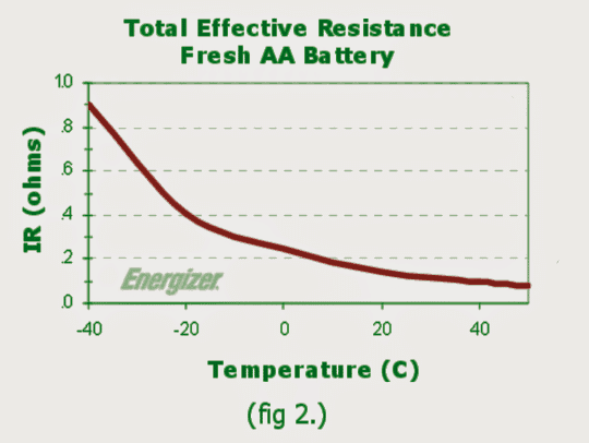
Wintry conditions could result in the electrochemical tendencies that materialize within the battery to decelerate resulting in reduction of ion activity in the electrolyte. Eventually, internal resistance would get higher as surrounding temperatures lowers
The graph (fig. 2) demonstrates the outcome of temperature on the total effective resistance of a brand new Energizer E91 AA alkaline battery. In general, internal resistance could possibly be determined in accordance with the voltage drop of the battery under a recognized load conditions.
Achievements could be impacted by approach, settings as well as climatic restrictions. The internal resistance of a battery needs to be deemed as a generic rule of thumb rather than as an accurate magnitude whenever it's applied it to the estimated voltage drop for a given application.


Questions & Answers
Sir which is more preferable between a sealed lead acid battery and a replaceable acid battery pls state with reason
victory, sealed (SMF) batteries are the advanced versions of the traditional unsealed lead acid batteries…..so SMF are better than the earlier LA batts since you don't have to worry about the acid status and condition for these batts.