• Skip to main content
  • Skip to primary sidebar

Homemade Circuit Projects

Need circuit help? Post them in the comments! I've answered over 50,000!

Blog | Categories | About | Hire Me | Contact | Calculators-online
You are here: Home / Power Supply Circuits / Making a Regulated 9V Battery Eliminator Circuit

Making a Regulated 9V Battery Eliminator Circuit

Last Updated on March 8, 2019 by Swagatam 4 Comments

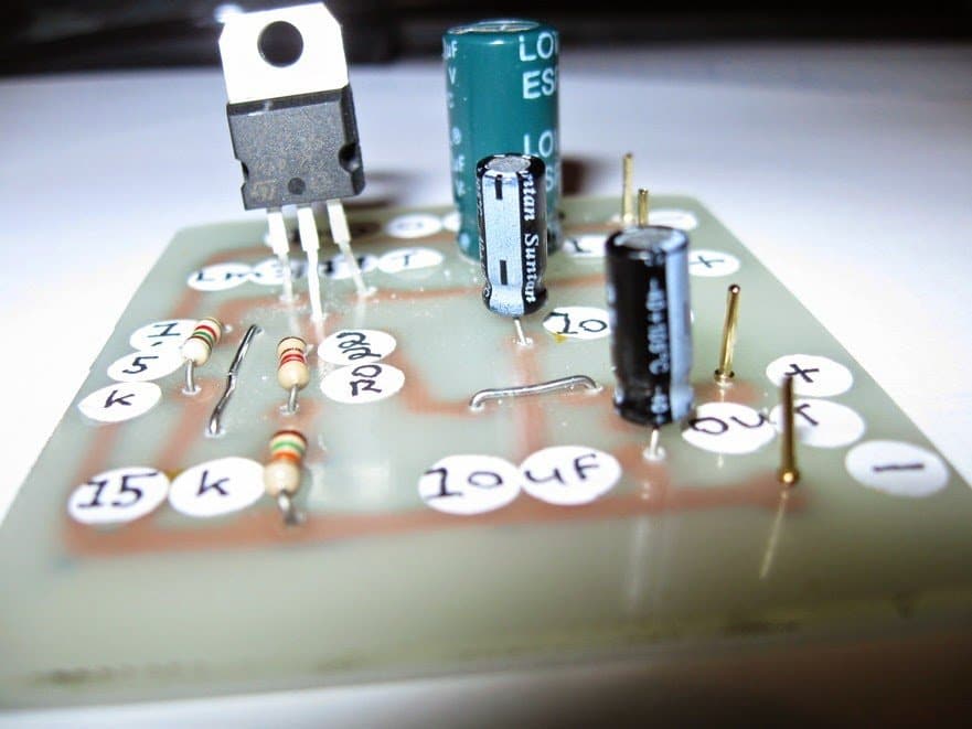
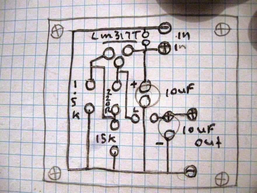
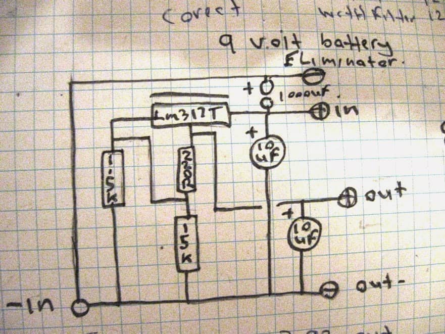
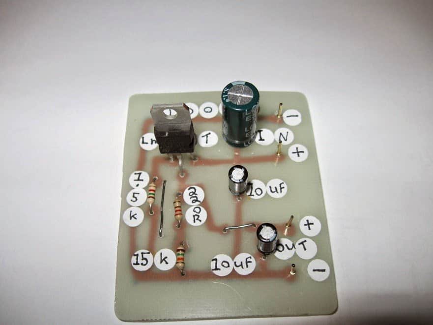
The post presents a regulated 9V battery eliminator circuit which was built and investigated by Mr. Steven Chiverton, an avid reader of this blog and an experienced electronic hobbyist. I have explained more from him.

Table of Contents
  • 9 volt battery eliminator circuit tests:
    • Conclusion:
      • Circuit Diagram and Prototype

9 volt battery eliminator circuit tests:

Circuits built 2x each circuit ive made a small modification to it buy adding a low esr 1000uf filetr capacitor between each circuits positive and negative output, latter after construction i decided to test them both but i removed the filer capacitor to note the difference between each 9 volts battery eliminator circuit.

First test was with the battery eliminator with the 1000uf low esr filter capacitor, i fed 12 volts dc into it and the output was a9.21 volts dc. Then the battery eliminator without the low esr filter capacitor was tested, i fed it the same 12 volts dc and the output was less at 9.05 volts dc.

Test 2 , i then changed the voltage output of my transformer to 9 volts dc , so i fed 9 volts dc into the battery eliminator with the 1000uf low esr filter capacitor and its output was 8.18 volts dc. Then i fed the same 9 volts dc into the battery eliminator without the 1000uf low esr filter capacitor and its output was 7.67 volts dc .

Test 3 , then i changed the transformer output voltage to 7.5 volts dc and so i fed that into the battery eliminator with the 1000 low esr capacitor and its output was ,6.75 volts dc. Then i fed the same 7.5 volts dc into the battery eliminator without the 1000 low esr filter capacitor and the output was then 6.2 volts dc .

Test 4, i then changed the transformer voltage output to 6 volts dc, and then i fed that into the battery eliminator with the 1000uf low esr filter capacitor and its voltage output was 5.30 volts dc. Then i fed the same voltage into the battery eliminator without the 1000uf low esr filter capacitor and its output was then 4.88 volts dc.

Test 5, i then changed the output voltage of the transformer to 4.5 volts dc and then i fed that into the battery eliminator with the 1000uf low esr filter capacitor and the output was then 3.92 volts dc then i fed the same voltage into the battery eliminator without the 1000uf low esr capacitor and its output was then 3.62 volts dc.

Last test test 6, i then lowered the transformer output to the last setting on 3 volts dc and fed that into the battery eliminator with the 1000uf low esr filter capacitor and its output voltage was then 2.44 volts dc . So then i fed the same 3 volts dc into the battery eliminator without the 1000uf low esr filter capacitor and its output voltage was then 2.29 volts dc .

Conclusion:

So my research tells me that the 1000uf low esr filter capacitor or any 1000uf electrolytic capacitor dose make a difference in providing better voltage output and filtering compared to not using the 1000uf electrolytic capacitor.

Circuit Diagram and Prototype
 

You'll also like:

  • How to Design a Bench Power Supply Circuit
  • lcdsmpscircuitLCD Monitor SMPS Circuit
  • DC-DC Boost Module (0.9V~5V) to 5V 600mA USB Step-up Board
  • adjustable regulated power supply circuit with current limit and short circuit protection100V Regulated Power Supply Circuit Diagram with Over Current and Short Circuit Protection

Filed Under: Power Supply Circuits Tagged With: Battery, Eliminator, Making, Regulated

About Swagatam

I am an electronics engineer and doing practical hands-on work from more than 15 years now. Building real circuits, testing them and also making PCB layouts by myself. I really love doing all these things like inventing something new, designing electronics and also helping other people like hobby guys who want to make their own cool circuits at home.

And that is the main reason why I started this website homemade-circuits.com, to share different types of circuit ideas..

If you are having any kind of doubt or question related to circuits then just write down your question in the comment box below, I am like always checking, so I guarantee I will reply you for sure!


Previous Post: « Battery Charger for Positive Earth Cars
Next Post: 10 Simple FM Transmitter Circuit Diagrams Explained »

Reader Interactions

Questions & Answers

Total Posts: 4
Newest Oldest
Pritam Bhowmik
August 15, 2014 • 12 years ago #25040

hi dada! its pritam again.. wish u happy independence day..
l u pls suggest me a low power inverter ,to drive 30watts light loads, design should be fair easy and super cheap to me..its badly needed bro… regards

Reply
SwagatamAdmin
August 15, 2014 • 12 years ago #25047

hi Pritam, wish you too a happy independence day!

you can try the following circuit:

https://www.homemade-circuits.com/2012/02/how-to-make-simplest-inverter-circuit.html

Reply
Pritam Bhowmik
August 3, 2014 • 12 years ago #24785

nice job bro.swagatam can u help me out i have built an adjustable power supply using lm317t..used 5k pot..but the o/p varies 10v-15v..

Reply
SwagatamAdmin
August 4, 2014 • 12 years ago #24800

Thanks Pritam, use a 10K pot, it'll provide a 1.25V to 20V range….but if your circuit is not showing 1.25V by varying the 5K pot, it means there's some other problem in the circuit, check it thoroughly for a possible error.

Reply

Need Help? Please Leave a Comment! We value your input—Kindly keep it relevant to the above topic! Cancel reply

Your email address will not be published. Required fields are marked *

Primary Sidebar


My Youtube Channel

Circuit Simulator

circuit simulator image


Subscribe to get New Circuits in your Email


Categories

  • Arduino Projects (95)
  • Audio and Amplifier Projects (134)
  • Automation Projects (18)
  • Automobile Electronics (103)
  • Battery Charger Circuits (88)
  • Datasheets and Components (109)
  • Electronics Theory (149)
  • Energy from Magnets and Earth (40)
  • Games and Sports Projects (11)
  • Grid and 3-Phase (20)
  • Health related Projects (27)
  • Home Electrical Circuits (13)
  • Indicator Circuits (16)
  • Inverter Circuits (99)
  • Lamps and Lights (162)
  • Meters and Testers (72)
  • Mini Projects (28)
  • Motor Controller (68)
  • Oscillator Circuits (28)
  • Pets and Pests (15)
  • Power Supply Circuits (91)
  • Remote Control Circuits (50)
  • Security and Alarm (65)
  • Sensors and Detectors (107)
  • SMPS and Converters (45)
  • Solar Controller Circuits (60)
  • Temperature Controllers (43)
  • Timer and Delay Relay (50)
  • Voltage Control and Protection (44)
  • Water Controller (37)
  • Wireless Circuits (31)


Other Links

  • Privacy Policy
  • Cookie Policy
  • Disclaimer
  • Copyright
  • Videos
  • Sitemap

People also Search

555 Circuits | 741 Circuits | LM324 Circuits | LM338 Circuits | 4017 Circuits | Ultrasonic Projects | SMPS Projects | Christmas Projects | MOSFETs | Radio Circuits | Laser Circuits | PIR Projects |


Recent Comments

  • Swagatam on True MPPT Solar Controller Circuit using IC 555
  • Swagatam on Electronic Circuit Projects, Tutorials, and Practical Engineering Solutions
  • Swagatam on Simple 20 watt Amplifier Circuits
  • Miracle on RC Helicopter Remote Control Circuit
  • Dale on Simple 20 watt Amplifier Circuits

Social Profiles

  • Twitter
  • YouTube
  • Instagram
  • Pinterest
  • My Facebook-Page
  • Stack Exchange
  • Linkedin

© 2026 · Swagatam Innovations