A Fence charger or energizer is an equipment which is used for charging(electrifying) a fence or a boundary in order to protect the inside premise from human or animal interventions.
Since these boundaries are mostly of large fields and parks, are normally away from the main cities, and powering them through some renewable option becomes more suitable than from utility grids which may become difficult to acquire in such remote areas.
The circuit of a solar electric fence charger explained here does not depend on traditional power source for operating, rather gets it 24/7 from a self sustained solar power conversion set up.The circuit is very simple to understand.
The fence charger circuit is basically a switching circuit which involves a few diodes and a high voltage capacitor.
How the Circuits Works
The diodes are used for rectifying the AC from a small step up transformer so that it gets stored inside the high voltage capacitor.
When this voltage reaches a particular threshold, the SCR fires and discharges the entire stored voltage inside the capacitor.
The above discharging of the capacitor is done or rather dumped inside the primary section of an automobile ignition coil.
The sudden dumping of the above high voltage inside the ignition coils primary, steps up the surge into several thousands of volts into the secondary winding of the ignition coil.
This stepped up voltage is used for energizing the fences or the boundaries appropriately.
However the above operations requires an AC input at the levels of around 100 to 220volts.
This voltage is generated by suitably processing the input DC from a solar panel set up.
The voltage from the solar panel is first controlled to a suitable level and then it's used for operating a triggering circuit.
The triggering circuit consists of a IC 555 oscillator which switches the voltage obtained from the solar panel controller into the transformers input, so that the output from the transformer generates the required 220V AC for powering the ignition circuit.
The solar panel output also charges a small 12V/7AH battery so that the power can be used after dusk, when sun energy is not available.
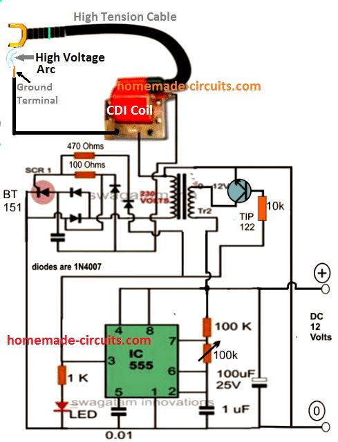
Parts List
- 10k, 100k, 1k 1/4 watt 5% = 1 each
- 470 ohms, 100 ohms 1/2 watt 5% = 1 each
- preset 100k = 1no
- Capacitor 1uF/25V, 100uF/25V electrolytic - 1 each
- Capacitpr 0.01uF disc ceramic = 1 no
- Capacitor 105/400V PPC = 1no, near the SCR
Semiconductors
- 1N4007 = 4 nos,
- IC 555 = 1no
- LED red 5mm = 1no
- Transistor TIP122 = 1no
- SCR BT151 = 1no
- Transformer = 0-12V/220V 1 amp
- Ignition Coil from 2-wheeler or 3-wheeler
The above circuit can be powered through the following solar panel current controlled battery charger circuit:
For complete explanation of the circuit please refer this solar voltage regulator circuit.
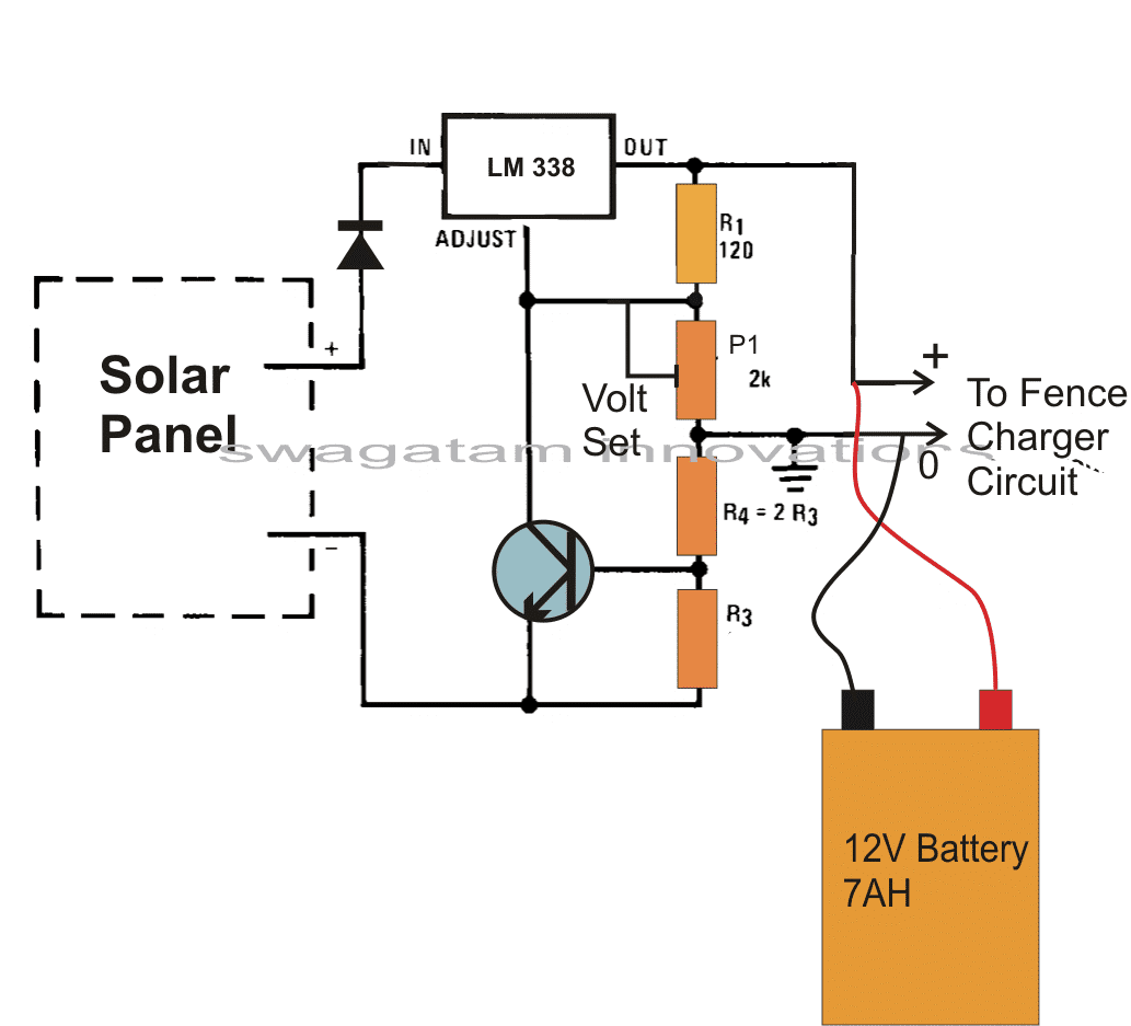
Parts List
- R1 = 120 ohms
- P1 = 10k pot (not 2k)
- R4 = replace with link
- R3 = 0.6 ohm 1 watt
- Transistor BC547 = 1no
- IC LM338 = 1no
- Diode 1N5408 = 1no
- Solar Panel = 16 V / 2 amp
- Battery 12 V 7 Ah
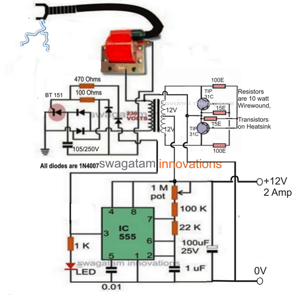
Fence Charger using a Stand-alone Inverter
Video clip showing the working details of the fence charger circuit. The video basically highlights the strength of the sparks generated by the CDI coil and how effectively this can be used when integrated with a farm fence.



Questions & Answers
Hello, my name is Eugenio, and I am writing from Argentine Patagonia. (Translated via Google.)
Please excuse the brevity, but my English is very poor.
I read this article on your blog—it is very interesting—and I would like to know if certain modifications can be made.
Specifically, replacing it with a ferrite transformer.
What would the calculations for this transformer be, and what other changes would the circuit require?
Hi Eugenio, you can easily use the following online calculator to design the 12V to 220V ferrite transformer, do not forget to put an air gap between the E cores.:
https://www.homemade-circuits.com/smps-flyback-boost-converter-calculator/
Dear
r u recd my last file?
Dear
thanks for reply
Actually i need solution for this design. i say sorry for jpg & now sending u pdf.
i need more output power , so for that may i choose 50mfd/440 Cap? & change T1 data with MOSFET also?
pl guide me .
Nitesh,
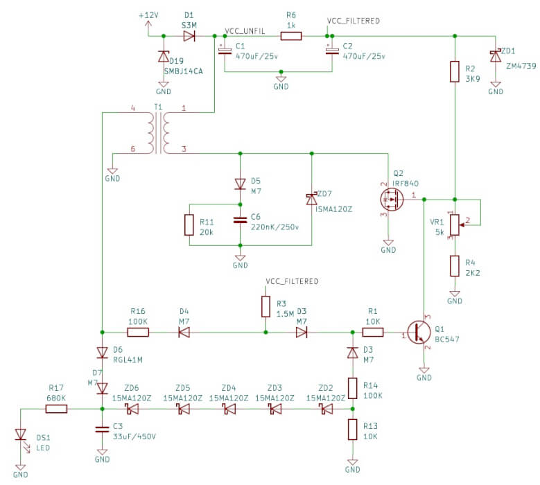
Increasing C3 value will not help, in fact it might do the opposite….instead you must increase the voltage rather than the capacitance. See that chain of Zener diodes, ZD2 —-to ZD6. They are 120V zeners that cut off the charging when it hits a certain limit. If you add another small Zener diode in series to that string, it will let the capacitor charge to a higher voltage. But make sure to keep the maximum voltage under 400V because that C3 capacitor is rated for 450V….
Also, try using a larger ferrite core for T1 that can handle more magnetic energy without saturating, or change the windings.
Increase the secondary winding turns and also use a thicker wire, or use 2…3 strands of thinner wires together to make one thick wire.
Or if you want to keep the same winding, just decrease the primary side winding little bit.
Also, try tuning the MOSFET bias network (R2, VR1, R4) to ensure Q2 turns on sharply and push more raw power to the high-voltage side.
Dear
What is the value of zener connect in series with ZD2 toZD6?
My ferrite is ETD34 with Lp =135mh @6.25 ohms , Ls=820uH @0.09 ohms .
What this DCR do? is effect on power or just control loss of primary side wattage? suppose if i decrease primary side inductance with big core ETD39 then it give some effect on output power?
i have all DSO voltage of Drain , Gate & Cap charging .May i sent it ?
second instead of IRF840 & may i choose some big current rating with high Bvdss then does it good choice? because now my gate voltage is max 6 v.
May be Mosfet is not full on?
Nitesh…..Add small Zener like twenty four volt in the string. It will increase capacitor voltage nicely but keeps it safe so it wont burst.
You mixed up the coil readings. High ohms is output side and low ohms is input side. Low resistance means less heat so wire thickness is not your problem here.
Yes, use the bigger ETD39 core and make input turns less. Big core holds more power without locking up, so capacitor will charge super fast at high speeds.
Your six volt gate voltage is very bad. That MOSFET is only half open, making it hot and blocking power.
Bigger transistor is good idea but first fix the circuit to give at least full 12V to the gate.
i need to understand C3 charging time ? Because it 25mfd/450 ( i cancelled 33mfd) . And due to 5 zener in series of 120 v then zener loop only conduct 120×5= 600 v. Then how can Q2 ( IRF840) became off? Need to understand roll of R6(100K) & D4(M7)also..I understand Mosfet On time but less clear C3 charging time with MOS off. So if i add 24v zener extra then charging time increase or decrease?
Dear….C3 does not charge during one long MOSFET OFF period. Instead the ferrite converter keeps switching Q2 ON and OFF thousands of times per second. Every time Q2 turns OFF, then magnetic field inside T1 collapses and produces a high-voltage pulse which passes through D6 and D7 and adds a little more charge into C3. So the C3 gets charged by thousands of small energy pulses….
The five 120 V zeners are not directly connected across C3, otherwise the regulator would wait until around 600 V before acting. Instead… the voltage from C3 is sampled and scaled through the resistor and diode network, so the zeners begin conducting when C3 reaches the intended operating voltage.
R16 (100K) mainly limits the current into the sensing network and isolates the high-voltage capacitor from the regulator section. D4 (M7) allows the sensing current to flow in one direction and prevents unwanted reverse current paths.
If an additional 24 V zener is connected in series with the existing zener chain then regulation threshold will increase. As a result… C3 will charge to a higher voltage and the charging time will become longer because more energy must get stored in the capacitor before the oscillator can get turned off.
Clear..
The voltage from C3 is sampled and scaled through which Resistor & Diode. Give me value of designator.
How can R16 (100K) mainly limits the current into the sensing network , with secondary side negative voltage or positive voltage bcz after R16 there is D4 & reverse direction. so path not clear
in short feed back loop with c3 charge ref not proper clear
if i ++ gate voltage of mosfet then it proper switch but due to that what acutely happened, output power increase?
i connect zd1 (4739) . May i ++ this value for ++ gate voltage ? my system volt is 12v. so what max value i choose for zd1?
i am giving some file for better ref with gate volt 6v .at that time c3 wave, drain wave, gate wave
does it show spike at drain & gate side? if yes then possible to rectify?
https://www.transfernow.net/dl/20260623yol15mrg/DCj1060i
The C3 voltage is mainly sensed through this path:
C3 (+) >> ZD6-ZD2 chain >> R14 (100K) >> D3 >> R1 (10K) >> Q1 base.
R13 (10K) gives the return path to ground and also helps to bias the sensing circuit. R16 (100K) and D4 (M7) are not the main divider for sensing C3 voltage. They are more related with the transformer secondary feedback and isolation network and help to block unwanted reverse current paths.
From your waveform, we see the gate voltage looks around 6 V. The IRF840 generally likes around 10 V to 12 V at its gate for proper switching. At only 6 V the MOSFET may not turn ON completely, so its ON resistance becomes higher, it may become warmer, and less power gets transferred to the transformer.
Increasing the gate voltage may improve switching efficiency and allow more energy to go into the transformer which can charge C3 faster and may increase the output power. But… the gate voltage should not go beyond the maximum VGS rating of ±20 V.
The 9.1 V zener ZD1 (1N4739) is mainly there for clamping and protecting the MOSFET gate voltage. For a 12 V supply, trying a 10 V or 12 V zener may improve the gate drive but increasing it too much is not advisable.
The drain waveform does show some switching spikes which are normally seen in flyback converters. The gate waveform also looks a little noisy. These spikes can be reduced maybe by improving the snubber network, using a better transformer winding layout, keeping wiring short and making sure that the drain clamp zener is working properly.
when i connect 25mfd /450v then DSO shows me ideal time arround 500ms with 10k bias of 547 & 100k value with 5k pot on gate. But when i connect 50mfd/450v then there is no ideal time. i need idea time & then cap should be discharge. what will i do?
when you increase C3 from 25 µF to 50 µF, then converter has to give out almost two times the charge before the capacitor reaches the cut-off voltage. So the MOSFET keeps switching for a longer time, and therefore the “idle time” becomes very small or may disappear completely. This is normal.
If you want the idle time back, then either reduce the value of C3…. increase the charging power of the converter (using bigger transformer or stronger gate drive) or reduce the cut-off voltage slightly. If you just increase C3, it will not give both a long idle time and the same charging speed.
Dear sir
in my current circuit i change IRF 840 & place IRL630 & replace 547 with BD139 only & just tune some gate voltage by pot value & 3.6k. i add 50k pot & increase its value .& also down 3k9..Now 50mfd capacitor charged & also shows hold time & system consume 1.5 amp to 100ma. now there is no problem that it not constant. But mosfet hit. it also connect with heatsink. I check after 5 hours it really hit but no fire. But heat is more.
now for reduce heat what can i do? may i used BD139 & BD140 push pull type gate driver & adjust gate value with 10E? and is there any other mosfet give good result.
Hello Nitesh, that sounds great, congrats to you..
Yes, you can certainly use BD139/BD140 gate driver to increase the gate drive current. If it still heats up too much, you can consider upgrading the MOSFET or put two IRF840 in parallel with separate gate resistors…
Many things clear,execpt
The C3 voltage is mainly sensed through this path:
C3 (+) >> ZD6-ZD2 chain >> R14 (100K) >> D3 >> R1 (10K) >> Q1 base.
But zener rating in 120v each ,so total 600v .
so at which point or time it start to sense? ,bcz c3 value is 450 max. & .while mosfet cycle continue in between ( at that time ) C3 reach up to 650v or 700v & control last 450v? this is not clear in depth.so give brief explain.
I think there is some aspect that is not correctly identified in the schematic.
I do not think C3 is charging to 650 V or 700 V and then being regulated back to 450 V. If that were happening, then 450 V capacitor would be under severe stress and could get damaged.
The best way to verify this is to directly measure the DC voltage across C3 during operation. If the measured voltage is only around 250 V to 350 V, then the 600 V zener threshold theory cannot be correct and there is likely some mistake in the zener value identification or schematic interpretation.
Dear
i will update shortly & again verify Coil input & output side both L & R
Thanks
Dear
yes feedback sense zener is 120v each. & when i choose c3 value is 25mFD/450v .This is ac capacitor which we generallly choose in motor. so may be it DC voltage is diff. it goes up to 600v. & run up to long time. i have less idea for current .
Now today i am fit 50mFD/450 cap & cut one zener then my zener loop total voltage is 480v & now C3 accross volatage is 500v.& when i change R13 value from 10k to 20k then my C3 also get good charge with some idea time also then dischage. THis result is good for me. & i am satisfied.
u give me good support for understand & clerity.
Now whole ckt consume 600 ma & i need 1A without change C3 ideal on & off time so what to do? may i low primary turn?
OK, that sounds great.
Yes decrease the primary winding turns slightly, and also don’t forget to increase the gate voltage of the MOSFET to 12V…
Dear
Can u add better gate driver ckt instead of current work with same feedback loop of zener chain + R16 (100K) etc. Because when i tune vr1 value & R2 value little bit down 2.5k with zd1 is 12v . My gate voltage little bit high & now 8v insead of last 5v..5.5v.. so i need better gate driver logic. either BD139+BD140 push pull type.( or any ic type gate driver) I have less idea how to add this ckt in my exiting diagram.
so guide me& give me pdf please. .
But in input is 12.5v & then D1 drop 0.7 v so actual vcc filter when i measure it 11.9 v. so 12 v zener i already used & it not conduct .. After then Vgs = 7.8 volt only. i think feedback loop thrue it drop & due to that gate not open full. Once gate will open then may be ckt imporve. i also set R2 value 1k & VR1 10k. then gate volt little improve & 7.8v .before this change it 6v .
Please don’t use VR1 or a preset, use a fixed resistor of 100k, and now check the gate voltage….so the MOSFET gate has one 1k from +12V and one 100k to ground.
I don’t think an extra gate driver is required, you just have to do the following to improve the gate drive for your circuit:
Make ZD1 = 12V,
Replace R2 with 1k,
Remove VR1, it is not required, and use only one 10k resistor (R4) between gate and ground.
Ok. will do Primary winding less . with 50mfd/440v i see C3 charge @500 v which i need & little bit idea time ( horizontal time ) & then C3 discharge with R13 is 20k at gate volate 5v max with 9.1z But when i fed 12v zener my gate voltage ++ but that idea time gone out.so i need idea time must. Second when that idea time occures ,mosfet is on Or off?
i show u that idea time line in attached graph.
yes u are right. when i increase gate voltage with R2 is 2.2k & vr1 25k then gate voltage is 8.5v to 9v. but input current is no more constant .Now it must be modified feedback loop. Now i came to finial point. To design new circuit need time & i will think. Is it possible to modified feedback loop ? second from where i will took trigger pulse in CDI . bcz in my ckt there is finial output is HIKV transformer secondary which produce around 11kv , so little less clear that this CDI ckt will perform or not with HI kv Transformer. More better if u give feedback ckt with modified for more input current constant then good for me. Other wise i will think new.
sir in this ckt i used 25mfd/440 v ac cap( which we used generally in motor) ,
For DC 440 × √2 = 440 × 1.414 ≈ 622 VDC, so when i connect 5 series of 120v then there is no big problem & cap c3 across 600v & it work from last many times. & ckt consume 700 ma approx. but 700 ma not constant . it fluctuate & drop down also upto 450ma. but it stable between 450ma to 700 ma , now when i cut 1 zener & keep 4 zener then C3 across 500v . That i understood now feedback loop threshold. but after reduce one zener ,consumption down up to 90 ma to 700 ma. This is the main issue. i need C3 across 500v & ckt will stable from 450 ma to 700 ma . this is my main issue. so after spoil so many time now i judge, there for i change root & goes to +++ gate voltage. second when i ++ gate voltage up to 8v with 500 v across C3 then ckt consume 1amp to again 90 ma. ( falls down).In short i need 500v across C3 with ckt consumption 450 ma to 1 amp ( or may be 500ma…600 ma to 1 ma) if consumption falls down more then at that time no more spark on secondary side high kv transformer.
i also change 20k value at the end loop zener but no more result, 1.5m value ( start up for 547) . May i used logic level mosfet ? . now my peak drain is 60ma max & drain level 54v appox. so no more spike . so may i choose 200v VDS mosfet is inuff?
Nitesh, I think the main issue is no longer the MOSFET gate voltage. The current dropping from around 1 A to 90 mA indicates that the feedback regulator is turning the oscillator ON and OFF after C3 reaches the preset voltage. This burstmode operation is normal for this type of charger.
Changing to a logic-level MOSFET or a 200 V MOSFET might not solve this problem. please do not use a 200 V MOSFET because the drain can have very fast switching spikes that are not always visible on the oscilloscope.
If you want 500 V across C3 with a more constant input current then the feedback loop itself might need to be modified. If you just increase the gate voltage or changing MOSFETs will not keep the input current constant once the regulator starts limiting the output.
Do you want some other circuit which will work 100% without any fault, let me know…
You can also check this design:
https://www.homemade-circuits.com/dc-cdi-circuit-for-motorcycles/
Ok.will check with 2 channel DSO for ideal time mosfet is on or off
I think the “idle time” you marked is most likely the interval after the energy transfer is completed and before the next switching cycle starts. It is probably not the MOSFET ON time.
When you use a 12 V zener, the gate drive becomes stronger, so the IRF840 transfers more energy per cycle and the idle time may reduce or disappear. This is not necessarily a problem.
To confirm whether the MOSFET is ON or OFF during that interval, you will need to compare the gate waveform and this waveform simultaneously using two oscilloscope channels.
Also, if C3 is reaching around 500 V, please be careful because that is already above the 440 V capacitor rating.
Yes, I saw it but the diagram is too large and unclear, so I found it difficult to understand it.
Instead of going with such complex circuit, why not use the above SCR based simple design which is 100% tested.
is CDI circuit work as per my high kv fence ckt.? how can i apply trigger pulse in CDI circuit for make fance circuit.
i need atlese input constant current value 1amp to 750 ma then good or 1amp to 500 ma then also ok but no more falls. Bcz if it falls up to 90 ma then spark energy low at that time .
in now exiting image i do lot of practical with gate volt ++ . but feedback loop issue. pl modifed in same feedback loop ..if it solve then my time save for make new one
A standard fence charger should look like this:
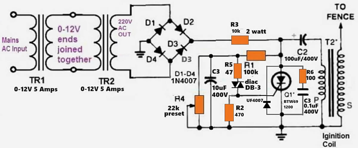
It is difficult to modify your design because it too large and confusing, a fence charger circuit does not need to be so large and complex.
If you want constant current, we can easily add it in the above type of design.
Dear sir
generally i have seen that in all fence charger Hi-kv Pulse transformer one lead goes to Earth & second lead connect with fence.
in above your design only shows hikv transformer lead goes to fence. so what about Earth connection ?
second is it possible to run this with 12v battery instead of 220 v ac to 12 vac?
suppose one should operate with ac line then good but when there is no ac line in agriculture area & run with Battery 12v then what change should be require?
Nitesh, see the bottom line of the circuit, having the earth symbol, the line must be terminated and connected with a physical earthing, created using an iron rod, deep into the soil.
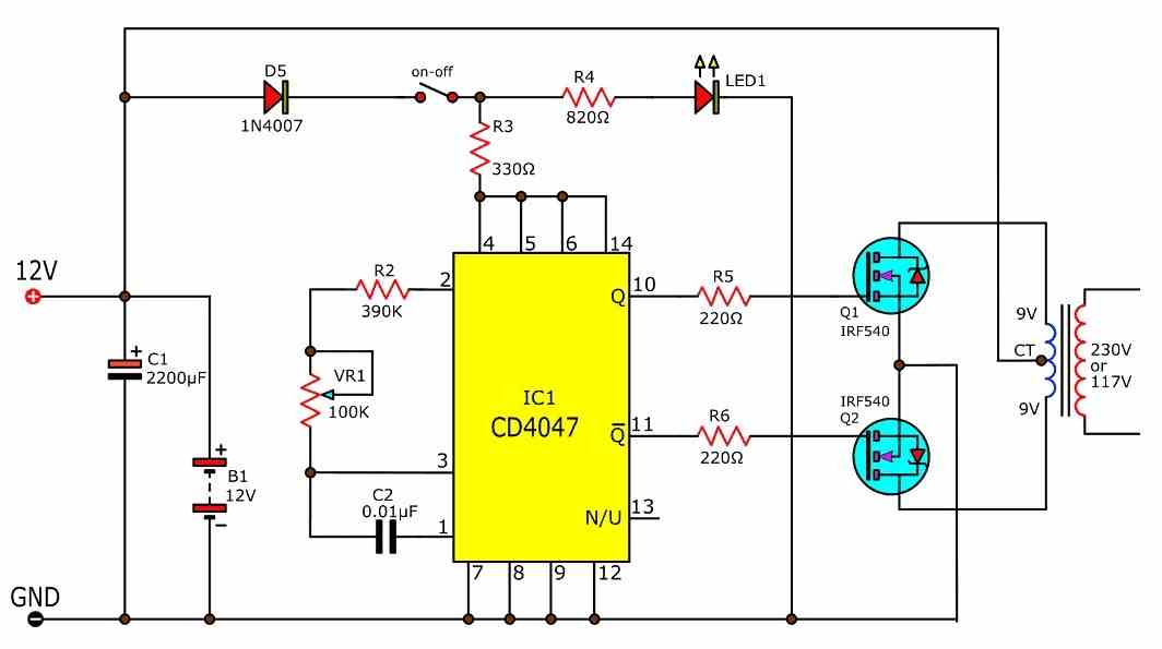
Yes, it is absolutely possible to run this setup on a 12V battery, using a 12V to 220V inverter. Just remove the two transformers and feed the bridge rectifier with your 220V AC from the inverter.
Do you have a layout of a circuit board for these designs?
Solar Powered Fence Charger Circuit
Sorry, I do not have a PCB layout for this project…
Hey Swagatan,
I’m planning to use the first circuit to protect a hive from bears.
– The output cap is a ”PPC”, what is it? Could an electrolytic capacitor be used instead?
– I’ve read that you need about 1 joule to deter bear. Using the formula W=0.5 CVsquare and 220V, I get the need for a 41 uF capacitor. Is it still safe for human beings? It is too much in general in your opinion? It seems like a big upgrade from the 1uF capacitor.
– Should I increase the value of the output cap, do I need to increase the watt of the 100 and 470 ohm resistor?
– From what I have read about IC555 and calculated, this circuit give about 4,8 pulses per second, am I right? I need to increase the value of the resistors and cap at the right of the IC to diminish the pulse frequency?
Thanks for your help.
Hi Jean,
The output cap should be specifically a PPC or MKT. You can search online with the phrase PPC capacitor, you will be able to get an exact idea regarding its type.
I am not sure about how much joule would be required, but the output from this generator is around 27 kV enough to kill a human being within minutes, so it should be enough to scare away any wild beast, even an elephant, according to me.
So no changes would be required in the existing circuit.
In the 555 circuit you can adjust the 100K pot to get the required ON/OFF timing, yes it will produce 4.8 Hz with the existing parts, which can be reduced by increasing the value of the 1uF capacitor, which can be an electrolytic capacitor
Thanks for your fast answer Swagatam.
Let’s say I’d want to energize more than a 100m of fence, what change would I need to do to the circuit?
I think for 100 meter coverage you can can build 10 such units and install them after every 10 meters. This will ensure uniform voltage range across the entire 100 meter area. Using a single powerful unit may not be good, since the voltage level might not be uniform across the full 100 meter distance.
You say the ignition coil is from a two or three wheeler. Does this mean that a normal 4wheel car ignition coil cannot/should not be used?
All ignition coils will work, but 2 wheeler coils are cheaper and have modest amount of current which may be suitable for fence charger application
Thank you!!
Where can I get the circuit board to make the fence charger??
Sorry PCB will need to be made to order
hello mr Swagatam. thank you for the work youre doing. i request you to help me with the list of components used in making the solar electric fence energizer
Hello aguma, I have updated the parts list in the article
Hello Swagatam,
Thank you for sharing.
Do you possibly have a circuit to test the output voltage of the coil to the fence, preferably a circuit that uses high bright LED’s?
Hi Swagatam,
Thank you for your reply.
Your suggestion to use a resistive divider with 1Mohm resistors sounds promising, if you have the time would you care show how you would go about calculating a divider to measure the output voltage, (20KV), of your fence charger for example? I am also a little confused how a voltmeter or digital multimeter can measure the voltage when the maximum scale is 1000V DC.
Your assistance would be appreciated
Hi Tracer, The formula is:
Vout = Vin (R2 / R1 + R2)
Where is Vout is the meter voltage reading
Vin is the required high voltage value.
R1 is the high resistance value which can be 1M
R2 is the low resistance value which can be 10K.
R1 must be at the + side of the high voltage supply, R2 on the – side.
Meter should be connected across R2
Meter scale can be any lower DC range
Hi Swagatam,
Thank you for the information you have provided, however I really don’t really understand what you are trying to say to help me find a solution. As I am dealing with High voltages I will keep on searching until I can find a safe solution to prevent damage to my test equipment and myself. I do appreciate your attempt to help
Hello Tracer,
an LED will not give any useful information. Instead you can put a resistive divider using a series 1M/10K resistor, and connect a DC voltmeter across the 10K. The result will be 100 times smaller than the output voltage, and therefore can be multiplied with 100
I wholeheartily thank you that you are doing a great job.
I have a problem that I want secure 2km agriculture farm but this circuit cover only 100 meter.
What machine parts will I change that cover such a ( 2km ) large area?
You are most welcome!,
for increasing the range, I think you only have to upgrade the ignition coil specs…you can try a car ignition coil instead of the shown motorcycle coil
Hi sir your site is very good n I already used many circuit that I used in my farm n now I’m goin for this bcos after Diwali we are going to grow chilly so I need to fence it, it is 4 Acer of land .
1st . Is One circuit is sufficient for fencing 4 acre and what guage wire I have to use ???
2nd what is the voltage of bt151 and tip 122 , 1uf capacitor voltage
Thanks
Thanks sir, how to add siren to it and day night on off ,
Hi sir I have done that circuit on PCB
But I’m not getting sparks , I have used normal transformer, input 230v n out put 12v , 300 ma when I connected this I get output 11volt only n no sparks at ignition coil n transform er is getting hot n even tip122
Hi sir thanks for reply, I already check tip is connected prprly , facing tip towards us first pin is base( is comin from pin 3 of 555 through 10k resistor ) ,2nd pin collector ( goin to transform 12v side ) , 3rd pin is emmitir ( is connected to output of transformar 230v side , which is negative to CDI coil) tip 122 is getting very hot , pulsing rate is ok since very fast led is blinking , I’m getting output to 12v only from transformar ,
Pls help me sir , if you have any other circuit which give even 10kv also it’s ok
Hi sir it will be great if you could explain with the daigram , (now don’t have to use tip 122 ?)
Last part of scr , capacitor , n 100ohm resistor will remain same or change ???
N what if i connect output of if 555 to the input of invertor circuit
Sidhesh, the IC 555 will be required only to trigger the SCR, the inverter circuit can work independently, and will not require the IC 555 assistance…TIP122 will also be not required now.
I’ll try to update the design soon…
…I have updated the diagram, you can check it out.
Hi sir , I have completed the simple invertor circuit n it’s working , I have connected 10watt bulb n it’s glowing , it’s working fine , but my main concern is for fencing , pls tell now what should I do next
Hi Sidhesh, you can now build the CDI stage and configure it with the output of the inverter, for pulsing the SCR stage you will need a separate IC 555 astable circuit whose pin#3 will need to be configured with the SCr gate via a 1K resistor, and make sure to connect all the grounds together, you must connect the CdI ground, IC 555 power supply ground together, thi power supply can also be used for powering the inverter. If possible I’ll draw the design and update in the article…
Or is the differenct step up transformation
Or can I try with other invertor circuit of 45w output by giving input from the same circuit of urs only in place of transformar and rest as it is
Sorry it’s O/p 12v 300ma
I hope you have connected the 12V side with the TIP?? if yes then it should have worked
Hi sir I have done as u said but nothing change , but when I’m disconnect transformar tip is not getting heated up it remain cool I think there might be ptblom with the transform r ,
On transfrmr it is written as
07337100
I/p: ac 240v 50hz
I/p : 12v 300ma
Eng EI-350343
Or should I change the tranform r
Sidhesh, you are having difficulty with the IC 555 stage, you can try the following circuit, eliminate the entire IC 555 stage and replace it with this circuit. Don’t use TIP122 use any non-Darlington power transistor NPN
https://www.homemade-circuits.com/2012/02/how-to-make-simplest-inverter-circuit.html
Sidhesh, remove everything from the transformer secondary and first confirm whether the transformer is generating 220V or not.
connect a 1N4007 diode across collector/emitter of tip122, anode to emitter, cathode to collector, this is supposed to be already present internally for the transistor but just for extra safety I am recommending this.
now connect a 10 watt bulb across the 220V side of the transformer and check whether it is glowing or not…
the supply voltage should be around 12V 2 amp to the 555 circuit.
add a heatsink to TIP122 to keep it cool.
the concept is too simple, if the 12V primary of the transformer is pulsated with a 12V Dc, the secondary 220V side will accordingly pulsate and generate 220V DC, through magnetic induction.
this circuit was designed by me for auto-rickshaws and has been thoroughly tested, it worked immediately for me…
Hi Sidhesh, make sure the IC 555 is oscillating, to confirm replace the 1uF capacitor with 10uF or higher, check whether the red LED is flashing or not, it should flash rapidly.
The output of the trafo must generate pulsating 220V in response to this oscillations, also make sure you have connected the TIP122 correctly, and it is not faulty…replace the 100 ohm at TIP122 base with a 10K
Thank you very much sir , Ur great ,
Sir here instead of 2n3055 u mentioned tip31c is it same or different? Cos I have 2n3055
You are welcome Sidhesh, you can use 2N3055 also, no problem with that… since the current is low for this circuit I preferred using smaller transistors like TIP31,,,,
Sidhesh, for a day night switching you may have to use an external circuit and configure it with the fence charger, you can select one of the designs explained in this article:
https://www.homemade-circuits.com/2012/01/how-to-make-light-activated-day-night.html
for siren you might have to incorporate a vibration detector for detecting animal presence…it can be difficult to attach it with the fence charger and make it work…
I’ve used capacitor at scr 105/400v and base resistor for transistor tip122 is 180 ohms , when I checked input volt for transformar I’m getting 9.5 volt and out 11volt and transform is getting hot
it could be because your IC 555 is not oscillating or TIP 122 is faulty, or TIP not connected correctly
Thank you Sidhesh, I am glad you are enjoying my circuits,
Regarding the distance, I am not sure how much one ignition coil would be able to handle, you will have to check and verify this through a practical testing.
BT151 is rated at over 300V, TIP122C at 100V, the IC 555 1uF capacitor should be 25V, the one attached with the SCR should be 1uF/400V PPC
20,000 v is dangerous for human. So, what should be the output voltage, ehich will not affect human and can be use as fencing for animals.?
use 12V 2 amp as the input, this will make the 2kv very weak in current and not so harmful.. however it's your responsibility to check the results appropriately
In the above circuits, if you use a DC source with lower current then the 2kv will be not dangerous, it will produce a nasty shock but won't kill anybody…
That said, it's responsibility to make sure that the calculations are done correctly…
20,000 v is dangerous for human. So, what should be the output voltage, ehich will not affect human and can be use as fencing for animals.?
2kv can be dangerous to animals and humans only if it's accompanied with some higher current.
In the above circuits, if you use a DC source with lower current then the 2kv will be not so dangerous, it will produce a nasty shock but won't kill anybody…
That said, it's responsibility to make sure that the calculations are done correctly…
Would u give me the information about energiser used in this project sir..if posibl will u provide
it is a motorcycle CDI ignition coil
Hi. Is there any way to electrify a fence with a 12v source using a common ground?
I often want to park in bear country and in some areas they regularly open vehicles like tin foil wrapped burritos causing hundreds of thousands of dollars in damage annually. To use this circuit I would have to disconnect the battery's negative terminal which is time consuming and a pain in the ass.
The van wouldn't shock anyone (or any animal) until the paint was scraped off, so I would have no qualms about using a high watt circuit to deter bears in the process of destroying my vehicle.
Hi, you can use the circuit which is explained in the above article.
It's a common ground circuit but for electrifying the van body a separate battery will need to be used, or if the existing battery is used then its negative wire will need to be first disconnected from the van chassis, and then electrified through the high tension cable
Sir your mo,nomber
If we use resistor as current sensor than defenetly we have to use in series.so current pass through this resistance.but problem is current is not passing through resistor because current is passed through air by spark beetween two terminal of resistance.so resistance is not comes in picture.to overcome this problem i make three 100ohm 1watt resistance in series and put relay parallel across resistance.and i sucsess that relay is operating but on time is not more.and also spark is reduce so it is not used in large area.
the current limiting resistor should be used on the DC side tat is in series with the battery positive not on the high voltage side, and I am not sure to which circuit you are referring to??
But sir at higher voltage resistor is bypaas using spark and if we connect bc 547 at parrallel to the resistor then gap beetween two pin is small then spark gap so it is spark beetween two pin and its burnout.
which resistor are you referring to? without seeing the schematic I won't be able to suggest….
We make sence circuit only using ct coil used in elcb.by using op-amp like 741 or lm358
The spark gap beetween fence and earth is more than 1cm.but resistor size is small so there is spark beetween two terminal of resistance.if we use 1 watt resistance than it internally burnt because of high voltage.means it internally puncture.
I could not understand your question.
Hello Sir,
is there a way to easily monitor if the fence is working correctly (let's say I have multiple fences at home and have to check these daily) ?
1) fence is not broken (some kind of DC sensor at the end of fence?)
2) fence is somehow connected to ground (grass, bushes)
Could You provide a PCB or any help would be appreciated…
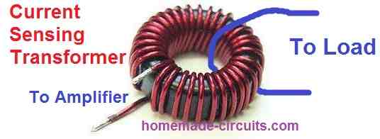
Hello Jargo, you can employ current sensing resistors with each fence charger module to sense if any of the output is shorted, but sensing a broken fence can be a bit complicated and might involve a too many connections across the whole system.
current sensing circuit can be implemented using the following explained method:
https://www.homemade-circuits.com/2014/06/simple-current-sensor-circuit-modules.html
Thanks
sir, is the combination of tip 122, transformer , and 555 , making a fly-back converter?
No polarity is there for this configuration, because the output is not linked through any kind of feedback circuit to the primary, therefore the two winding sides can be wired anyway round.
sir, i meant what's the polarity according to dot convention? whether dots are on same side or on opposite sides?
it will be the same, low voltage side towrads the transistors and the high voltage side towards the output
is the polarity of transformer tr2 is same or opposite?
yes it is suitable.
Hi sir,
1) is output of 555 timer used to apply gate pulse to SCR?
2) why have you connected output of 555 to transformer?
3) can we use tl 494 instead of 555 timer?
thank you sir…
555 is controlling the CDI coil by switching TIP122, TR2, and the SCR, in a sequence…
Umar, the capacitor side is the primary of the CDI coil.
Sir, which is the primary side of induction coil? Is it the one with which the capacitor is connected or the one with which cathode of scr is connected?
And my second question is whether 555 is also controlling the scr?
to switch the transformer at the 555 frequency
Sir what is the function of tip122?
TR2 can be any small transformer such as a 0-12V/500mA/220V or a 0-12V/1amp/220V.
SCR resistors can be 1/2watt rated
The TIP122 base resistor should be above 1K, @ 1/4 watt………100 ohm is incorrect.
1)sir what is current rating of transformer tr2?
2)what is the rating of 100, 470 ohm connected to scr, and 100 ohm connected to tip 122?
use 6V DC supply input
what changes we have to do for lower output say 10KV.?
P.S. thank you for quick reply…
Hi Umar, the CDI coil requires at least around 100 to 200V to produce the specified 20,000 volts, that's why the transformer is used for stepping up the 12V to this level.
TL494 can be used instead of IC 555
Is transformer tr2 a pulse transformer or simple transformer??
it's an ordinary iron core transformer
swagatam will u arrange the solar fence tested circuit pcb
would be difficult due to lack of time…
When I apply power to the circuit the tip122 locks on and just buzzes I know if I leave it powered it will burn the tip122 out what could be the cause I have double triple checked the work and cannot find the problem. any suggestions would be greatly appreciated.
that's not possible, if the IC555 works correctly, it's ought to oscillate the TIP122 and the transformer accordingly at the set frequency.
Increase the base resistor of the TIP1222 to 10K and the check the response.
if the trafo is an iron core type, then make sure the frequency does not exceed 100 to 200Hz…I think might be crucial to keep the TIP122 and the trfao cool
Does the 12 v Battery used to power the fencer circuit have to be 7AH or will any 12 v battery work? will a car battery damage anything?
the AH of the battery value can be anything, it won't affect the circuit as long as the voltage is within 15V
In the schematic P1 calls for a 1M potentiometer. later it is referred to as a 27K preset. Did you change it to a resistor?
I don't remember actually, but that may be possible, I might have changed the 27k to a 1M… because a 27K preset will generate a much higher range of frequency than the 1M preset which might not be suitable for the associated iron core transformer.
Hi Swagtam this is Suhas. Your circuit looks good.
Currently Im building this but dont know how to check output high voltage and current ??? Please suggest.
Also send your you-tube video link for this project.Thanks.
Hi Suhas, if you are asking regarding the solar panel measurements, it may simply done by connecting your multimter (in DC V range) prods directly across the solar panel terminals under peak sunshine, this will show you the voltage specs (open circuit voltage) of the panel, for measuring current you need to follow the same procedure again, but by keeping the meter in the DC ampere range…the reading will show you the amp spec of the panel (short circuit current)
I'll wait for the video and pics if possible…thanks!
hello sir
thanks for putting circuit.i am student of engineering and my project is solar fence guard.
in first stage i use step up transformer 12v/230v and charge capacitor.in next stage i discharge capacitor in output transformer.required output transformer is 230/10 kv but i dont know current rating of 230/10kv transformer.please suggest me the current rating of 230/10kv transformer.and what is its frequency.
frequency will depend on the oscillating frequency that you may be using to drive the trafos.
hello vikas,
divide 10kv with the secondary voltage of the transformer
Hy i have used bc 547 and when ckt start uts burn any idea also still i have not connected the ugnitiin coil in this
BC547 has no chance of burning, something may be not correct in your circuit.
thank u swagatam bhai ,
but i m facing 1 more problem that i can't get ic LM338 and scr BT151 so can u suggest me any other equivalent ic & scr … so i can get it…!
Hi Kalpesh, I am afraid there's no other reliable alternative for these two devices, because the specifications of these parts are unique and ideally suited to the proposed application, so I won't recommend any other equivalent because they could burn and get damaged overtime
and in second ckt… battery charger ckt what is the value of R1, R2(p1),R3,R4 .
THOUGH SOME OF THEM U HAVE PROVIDED. and transistor is also BT151 in second ckt…?
BT151 is for SCR1, the transistor in the charger circuit is BC547
please click the diagram to enlarge.
R4 is not required, could be removed.
R3 = 0.6 x 10/battery AH
btw i m working on ur ckt diagram …. it's really good.
hello… swagatam.
in ckt what is the value of capacitor just below the scr 1.
and value of capacor at pin 5 in IC 555 is .01 uf…?
hello kalpesh,
the value of the capacitor is 1uF/400V or 105/400V
pin5 cap is = 0.01uF or 103 ceramic disc
Great post. What is the output pulse waveform? is it a square wave?
Thanks, I am not sure about the waveform, so can't say.
sir howmany kilometers can use this circuit.
with iron wire not more than 100 meters.
what are the components for the charge controller circuit given above?
hello swagatam… here u have used TIP122 instade of BC547 transistor…… which is correct..?
transistor is BC547, rest is given in the diagram
yes it's possible by adjusting the 22K resistor, make the 22k resistor variable, this will allow you to select any desired pulse timing.