In this post I have explained an upgraded version of my previous mains 220V/120V high-low voltage cut off protection circuit which now includes a delayed restoration of power for the load with 3 LED power status indicators.
The idea was requested by one of the dedicated members of this website.
Circuit Objectives and Requirements
- I just followed you're explanation and is it possible that you can help us with the following:
- To design a safety circuit that should provide for household appliances for over-and under-voltage protection.
- The protective circuit must immediately switch off upon detection of low-and high-voltage household appliance and upon detection of normal voltage switch on again after 3 minutes.
Main Specifications
The protective circuit must comply with the following: If the line voltage is within the normal range (100 to 130V ac), it will wait for the protective circuit 3 minutes before the output will be energized. During these 3 minutes there is an amber
LED light. If the line voltage is outside the normal voltage, the output of the protective circuit will never be under tension. If the line voltage is less than 100VAC, the protection circuit "low voltage" must indicate by a red LED that lights up.
If the line voltage is present, the protection circuit must pass a voltage greater than 105 Vac "normal tension" it will indicate by a green LED that lights up.
Similarly, the line voltage protective circuit has to be higher than 130V ac "high voltage" will be indicated by a red LED that lights up. Only when a voltage is less than 125VAC, it must indicate the protection circuit "normal tension" by a green LED that lights up.
Upon detection of over-and under voltage protection, the circuit should give a beep of 5 seconds.
This should be constructed with an opamp oscillator circuit in this functionality.
Circuit Diagram
The Circuit Design
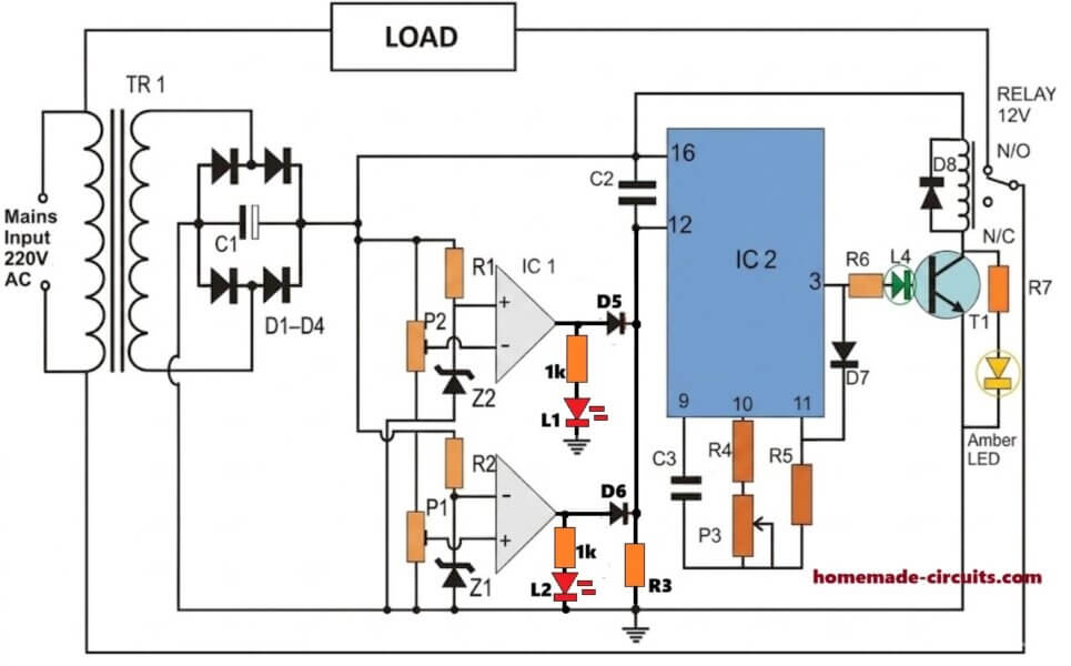
The above shown mains high/low voltage cut off protection circuit is an enhanced version of my previously explained design which had similar high low cut off protection feature except the delay timer stage which has been added in the present design as per the request.
The timer stage ensures a delayed power switch ON for the load each time the mains is cut off due to an abnormal fluctuating voltage so that the load is never subjected to an abrupt or random voltage switching situation .
The circuit also includes 4 distinct LEDs which indicate the corresponding mains voltage levels or status through their individual colors. The two red colors indicate high and low voltage situations respectively, the amber color LED indicates the intermediate delay counting status of the circuit, while the green LED informs the user regarding a healthy mains output condition.
The P3 preset or pot is used for setting up the delay time switch ON for the IC 4060 stage
How it Works:
We already know from our previous post that whenever the input voltage crosses the higher threshold, a logic high is created at the output of the upper opamp and when the voltage drops below the lower threshold the lower opamp generates a high logic at its output.
This implies that during both the conditions a high logic is generated at the cathode junction of the diodes connected with the opamp outputs.
We know that the timer IC 4060 is forced to reset in the presence of a positive trigger at its pin#12, and the IC stays disabled (output open) as long as a high is sustained at this pinout of the IC.
Therefore for so long the output from the opamps is held positive, pin#12 is kept high and subsequently the IC 4060 output pin#3 is held deactivated, which in turn keeps the relay switched OFF along with the mains load disconnected through the N/C contacts.
Now as soon as the mains voltage returns to its normal level, the high logic at pin#12 of IC 4060 is removed, so that the IC is allowed to commence its counting process.
The IC now begins counting as per the values set by C3/P3. Supposing the mains remains stable during the whole counting process, the IC counting finally elapses enabling a logic high at its pin#3, which triggers the relay and the load into action.
However suppose while the counting was in progress, the mains kept fluctuating, the IC would be forced to reset repeatedly and this would keep the output completely switched OFF making sure that the load was never allowed to face the unpredictable and fluctuating mains condition.
How to Set Up the Circuit.
Initially keep the power supply disconnected with the circuit.
Apply mains input to the power supply transformer and measure the DC output across the filter capacitor, and also measure the existing input mains level at the input of the transformer.
Let's say the mains voltage is found to be around 230V, which results in the production of a DC output of around 14V.
Using the above data now it may be possible to calculate the corresponding upper and lower cut off thresholds, which may be used for setting up the respective presets .
Suppose we want 260V to be the upper cut off level, and 190V as the lower cut off, the corresponding DC levels could be calculated with the help of the following cross multiplication:
230/260 = 14/x
230/190 = 14/y
where x represents the corresponding upper cut-off DC level and y the lower cut-off DC level.
Once these values are calculated, using a variable DC power supply, feed the upper DC level to the circuit and adjust the upper preset such that the upper opamp LED just lights up.
Next, in a similar fashion apply the lower DC level and adjust the lower preset until the lower opamp LED just lights up.
That's it! The adjustments for the upper high, and lower under voltage cut-off setting up procedures are complete, and the system can be now be plugged-in with the mains for the actual test.
Parts List
- R1, R2, R3, R4, R7 = 4K7
- R6 = 4K7
- R5 = 1M
- P3 = 100K POT
- C2 = 0.33uF
- C3 = 1uF
- C1 = 1000uF/25V
- P1,P2 = 10K PRESET
- Z1, Z2 = 4.7V/ 1/2 WATT
- D1---D4, D8 = 1N4007
- D5----D7 = 1N4148
- IC1 = LM358
- IC2 = IC 4060
- T1 = BC547
- RELAY = 12V/250 OHMS, 10 AMPS
- L1----L4 = LEDS 20mA, 5mm
- transformer = 0-12V/1 AMP or 500 mA
UPDATE
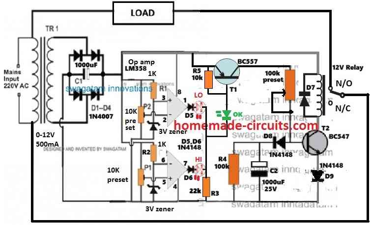
For a transistorized version of the above high/low mains protection with delay timer, you can try the following design:


Questions & Answers
Hi Swagatam,
Q.1 : I want to make “High-Low cut off protection circuit with delay timer stage” (With LM358 & IC 4060), but I do not want the timer to activate every time supply is applied (when power resumes). I want it to activate only when trigger is applied at the reset (pin 12).
Q.2 : How can I on the relay manually by interrupting the counting process.
Hi Rajesh,
To activate it manually, replace the C2 capacitor with an ON/OFF toggle switch.
To terminate the counting process, try applying a short positive pulse to pin#11 through a push button switch and check the response, see if that works or not…
Hello, good afternoon, Mr. Swagatam. I am really interested in building this circuit… The problem is that here in Italy, iron transformers are not easy to find… Everything is switched… The question is, can it be done without a transformer, with a capacitive source? Thank you very much.
Thanks you Carlos, yes that’s possible, you can find the diagram in the following article:
https://www.homemade-circuits.com/highly-accurate-mains-high-and-low/
Sir
Relay still contact if we applied 18 v as I set upper cutoff at 14.2 v
Did you remove the red LEDs? and now how much voltage are you getting at the cathodes of the D5, D6 diodes? Is the green LED always ON?
Yes I removed red leds if I in 23 v I get 20v at diode junction green is on and relay contacts if I give 14.2 v I get 12.6v at diode junction and relay still contact
Please compare the diode junction voltage with the base/emitter voltage of the BC557 transistor. If the base/emitter voltage is higher than diode junction voltage then the bc557 will always ON. You can try increasing the 1k at the diode junction to 22k or higher until the green LED shuts off…or you can try adding a 1k across the base emitter of the bc557.
I’ll check and reply
Ok what I have done is that pls correct me if I’m done anything wrong while adjusting low high presets
My low is 8.6v and high is 14.2
I set preset low and high with both voltage untill red led glow or I get voltage from op amp outputs
Yes, you have to get a high from one of the opamp outputs, either at high voltage or at low voltage, both opamp outputs cannot be high together.
No sir
I’m unable to make this don’t know what I am doing wrong relay contacts at high voltage Or tell me how to configure high and low opamp presets as while I giving 14v at high out put diode I get 12 v at some point of preset and 0 at last setting how to configure it properly I know I’m making mistake here somewhere
You can do the following just for testing purpose but it is not the final setting.
Let’s say you have 12v relay, and the low voltage limit is 11v and high voltage limit is 14v.
Now take a variable DC power supply and feed 11v to the circuit and adjust the upper opamp preset up/down until its output becomes just high.
After this increase the voltage to 14v, this should instantly cause the upper opamp output to become low….now adjust the lower opamp preset up/down until the lower opamp output just becomes high…now reduce the DC input to 12v, now both opamp output should become low….subsequently now increasing the DC to 14v must cause the lower opamp output to go high, and reducing the DC to 11v must cause the upper opamp output to go high….at 12v both opamp outputs must stay at 0v
Sir during 12v input 0v output from cathode junction but using bc547 single transistor without delay model relay not contact and 12v shows on relay coil
Hi Jas, sorry I couldn’t understand what you are saying
Do you mean you have removed the bc557 stage and connected the bc547 relay stage directly with the opamp output, and the relay is ON even while the opamp output is zero?
Yes sir i connect bc 547 with relay but relay not working
Relay will operate when the opamp supplies a voltage to the base of bc547.
How
Ok i input 8.5v and adjust upper opamp preset till it giving just give me output volts around 6.5 v and input 14.5v lower opamp preset adjust when I get output around 12v , now by adjusting both presets I get same voltages not higher or I get 0v, I set both preset when I get voltages above 0v but at between voltage like 9v to 13v no output from opamp kindly help
Jas,
I cannot understand your English.
If your your opamp output is high at 8.5v and 14.5v and 0v between these two limits then your circuit is working correctly.
Sorry for english
Ok ill tell what I’m done
I got 9 0 9 trans
And using 9 and 0 after bridge and cap I got around 12v ok
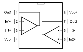
On ic lm358 pin no. (2) I connect 1k resistor and other end of resistor to +ve supply and same pin( 2) I connect 5v zener cathode and zener anode to ground
Pin no. (3) I connect 10k vr middle pin and other two pins connected +ve and -ve supply, pin no. (1) is output
On pin no. (5) I cionect 10k vr middle pin and other two pins to +ve and – ve supply
On pin no. (6) I connect 1k resistor and other end of resistor to +ve supply and same pin (6) I connect 5v zener cathode and zener anode connect to ground
Pin no. (7) is output
I’m using 12v relay coil one side connected to +ve supply and other end to bc 547 emmiter, bc 547 collector connected to ground, base connected to cathode junction
I think you made a mistake. The two opamps are oppositely configured. One opamp has preset on its (+) input and the other opamp has the preset on its (-) input….same for the zener diodes.

Please check the updated diagram below:
I’ll check and reply
Ok…
I made it temporary using your previous transistor version with delay circuit and working good, just if I want to cut at 14.2v it cut relay at 14.4v but anyways thanks will post final results
Ok, sounds good, you can improve the accuracy by using better quality presets or by using multiturn presets.
Hi by bypassing red leds it works but if using both leds relay connect automatically tried the updated circuit also
OK, please connect a 1N4148 diode in series with the green LED, and check again.
Hi now with diode it’s working good just green led glow continues on high and low
Try connecting green LED at the emitter line of the BC557, on left side of R5, and check the results,
No it’s still glow
Bring back the green LED at the base of T1, and now connect two green LEDs in series at the base and check the results.
In transistor version relay continuesly working no matter voltage is up or down
Please remove the red LEDs and check again.
I’ll check and reply
Hello, good afternoon, my name is Carlos and I am interested in the circuit but I would just like to know if you have a simple circuit that when the 220VAC network fails deactivates the relay, but when the power returns it has a delay of about 2 to 5 minutes to come back on. energize the relay.. Thank you very much in advance
Hello Carlos,
you can try the second circuit from the following article:
https://www.homemade-circuits.com/simple-refrigerator-protector-circuit/
Sir
In transistor version zener is 3v Or 6v
Hi Jas,
The zener can be any value between 3V and 6V.
How to use 24v relay on transformerless , transistorized version of the circuit
You can use a 9-0-9V transformer to get 18V AC output which after rectification and filtration will produce 25V DC for the circuit. This DC can be used for powering the circuit. The relay will also need to be replaced with a 24V relay. The capacitor voltage ratings must be increased to 50V.
Sir what if I want to use 24v relay on transformersless circuit pls advise
Hi Jas, I am sorry, I noticed it just now, there’s a serious mistake in the transformerless version shown below…you can see the dc supply to the opamp inputs is stabilized with a 12v zener diode, that means the opamp will not able to detect the ac voltage fluctuations, and therefore cannot detect and respond to the input ac fluctuations….that is why a transformer based circuit is recommended, as explained in rhe above article.
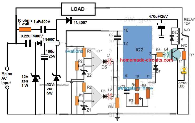
Can u provide same transistorized version circuit for 24v relay on 24v or 12v transformer
You can use the same circuit, nothing will change except the transformer and the relay. The transformer must be rated at 0-18v, 1 amp, and relay can be a 24v relay. The capacitor voltages must be rated at 50v or higher.
Sir
Will 24v relay coil works on 18v from transformer or it will need to boost
Jas, after full bridge rectification and filtration the 18V DC will become 25V DC which will be enough for the relay.
Greetings
Dear Swagatham,
The transistor version while working when it turn off and turn on the delay fail to work.delay is not discharge immediately to next on.please do a solution.
Regards,
Sison
Hi Dr. Sison,
the transistor version will produce the delay only during power switch ON. The delay has to happen, because the 1000uF base capacitor will charge slowly which will not allow the transistor relay to switch ON immediately, rather wait until the capacitor is fully charged. You can adjust the 100K preset to full resistance value meaning adjust it to full 100K resistance and check again.