In this post I have explained a simple yet very accurate temperature controller circuit using IC LM35, featuring an automatic cut off with a push button latch.
LM35 is a precision temperature sensor IC, which can be effectively used for detecting temperature differences accurately. For more details regarding this IC you can refer to this article.
Circuit Diagram
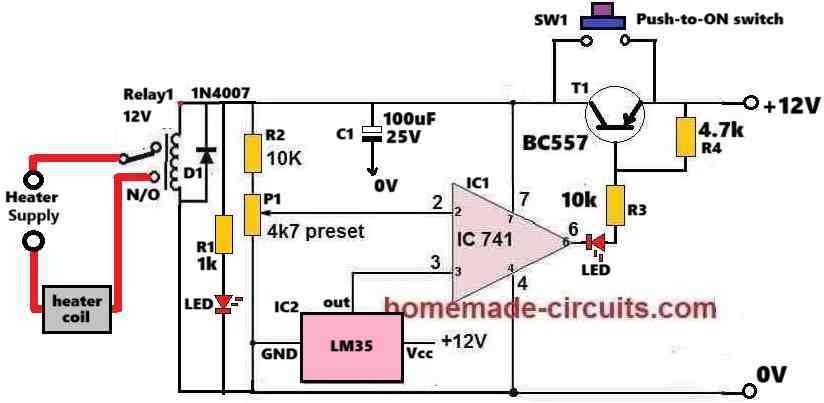
How the Circuit Works
The IC1 741 is configured as a comparator circuit.
Its pin#3 which is its non-inverting input pin, is attached with the output of the heat sensor IC2 LM35.
The inverting input pin#2 of IC1 is configured with a preset P1, which is used for setting the reference voltage at pin#2.
Whenever pin#3 voltage exceeds pin#2 voltage, the IC1 output at pin#6 turn high.
Conversely, as long as pin#3 voltage remains below pin#2 voltage, the output pin#6 of IC1 remains at 0V, or logic low.
At normal room temperature the LM35 output will be low which will keep the pin#3 potential of the 741 lower than its pin#2 reference.
Therefore, when the push button is pressed, the IC741 momentarily activates sending a 0V (low) to the base of BC557 which now conducts so that the whole circuit now gets latched even if the push button is released, and stays powdered through the BC557.
In this situation the relay switches ON and its contacts shift to the N/O points. Since the heater is wired with the supply through the N/O contacts of the relay, it is also switched ON.
The heater temperature now starts rising. Since the IC2 LM35 is attached with the heater, the LM35 also starts heating up which causes its output voltage at pin#3 of IC 741 to rise proportionately.
When the LM35 output voltage at pin#3 of IC1 741 reaches a point where it exceeds its pin#2 potential, the output of IC 741 instantly reverts and goes high.
As soon as the output of IC 741 goes high, it inhibits the negative or 0V supply to the base of BC557. Due to this the BC557 turns off.
As BC557 turns OFF, it breaks the latch so that the 12V supply to the circuit is cut off, the whole circuit along with the relay is turned off.
This also turns OFF the heater and the circuit returns to its previous original condition.
How to Setup and Test
Assemble the circuit as shown in the above diagram. Initially, do not connect any heater with the relay contacts.
Keep the P1 slider fully at the positive level or fully towards R2.
Switch ON the 12V DC to the circuit.
Push and release the SW1 switch momentarily. This should instantly cause the circuit and the relay to switch ON and get latched. Both the LEDs must illuminate.
Next, using a soldering iron heat the LM35 to the desired level. Monitor the temperature with an accurate thermometer, make sure it does not exceed 100° Celsius.
Once the desired temperature is reached, slowly adjust the P1 preset until the IC1 output turns high causing the latch to break and turn OFF the relay. This is indicated by the LEDs which are now turned OFF.
Repeat the above procedure a few times to confirm the results.
The circuit is now set and ready to work with an actual heater attached with the relay contacts.
Troubleshooting
If somehow the circuit does not work, please implement the following improvements in the circuit.
Please connect a 1uF/25V capacitor across the base/emitter of the BC557 transistor. This will ensure that the circuit does not start by itself during power switch ON, rather initiates only when the push-button is pressed.
Please remove R2 (10k resistor) and replace it with a jumper. This will ensure that when initially the slider of the preset is held at the positive side, the op amp output delivers a low logic without fail.
Also, connect a 1uF/25V across pin#3 of the IC and ground, this is optional.
After finishing the above operations, please follow the steps explained under "How to Setup and Test."
Parts List
- All Resistors are 1/4 watt 5% CFR
- 1k, 4.7k = 1 each
- 10k = 2
- 4.7k preset = 1
- Semiconductors
- IC 741, IC LM35 = 1 each
- Transistor BC557 = 1
- LEDs 20mA, 5mm = 2
- Relay 12V 10 amp = 1


Questions & Answers
sir I have changed nothing only just a preset I have lowered the value to the 5k and now it’s working! is this good ?
But as per our previous discussions, you were supposed to change the 10k resistor with a 470 ohms so that the MOSFET gate can get proper current, right? And also the 12V zener diode to 15v zener? Anyway, 24V cannot show at pin#3 of the opamp, because we have 12V zener across it. Something’s wrong in your circuit. If 5k preset works for you, you can use it.
hey there 👋🏻 sir how are you ! I have a question right now I’m facing a problem which is why I’m getting 24v maximum at lm358 at pin 3 ? and why the whole circuit is getting turned of at 9v ? previously I never faced this kinda issue but why now ? I have replaced bc546, bd140 and also new ic but then again same issue! why ?
Hey Neeraj, I am good, thank you!
The problem you are facing should never happen, because you already have a 12V or 15V zener after the 470 ohms you changed in place of the previous 10k 1 watt resistor.
That means the 10k preset is connected across this 12V or 15V supply, so how can pin#3 of the opamp get 24V?
Please check the voltage across this zener diode and confirm the results once again…
sir can we include a small series resistor (e.g., 10Ω) in series with each MOSFET gate ? for good current sharing? and if yeah then how ? and yeah I’m going with 15v zener and 470ohm 5w diode
Yes, you can do it in this way: From the gates of each MOSFET connect a 10 ohm resistor, and then join the other ends of the two 10 ohms with the common gate supply input. That’s all!!
no sir I can’t replace mosfets now but can we use 10k 5w or 2w resistor? and 15v zener diode or any other power resistor because serious changes can cause me so much now ! please 🙏🏻
You can use two 1k, 2 watt in parallel, to increase current, if you don’t want to use the extra BJT.
First, try with a single 1k 5 watt, if it works then good, otherwise use two 1k 2 watt in parallel, or use a single 470 ohm 5 watt.
Also, replace the gate zener with 15V zener diode…
So I need to buy 1k 5watt resistor and 15v zener diode? ? and also the resistance value is not too much lower nah ? like from 10 k to 1 k ?
Actually even with 1k, the current will be just 50 ma, which might be not enough to operate the gate of the high current MOSFET….in that case I would recommend using a transistor driver, as shown below….if possible replace the transistor with a Darlington transistor such as TIP122…

hello sir how are you I hope you’re fine I have a one question why my mosfets are getting crashed all the time I’m using 2 irf540n MOSFETs in parallel as you suggested me with the 12 V zener diode but after sometime one of the mosfets gets faulty but the other one stays perfect this cause circuit malfunction I checked it they gets heat up madly but is there any way so we can solve this issue without heatsink because I heard somewhere that limiting current at the gate of this mosfets can also cause malfunction and heat should we replace current limiting resistance 10k 1w ?
Hello Neeraj,
That’s correct. The 10k 1 watt resistor might not be able to provide sufficient gate current for the MOSFFETs. In that case, yes, please replace that resistor with a 1k 2 watt, or 5 watt wire wound resistor, and also increase the 12V gate zener diode value to 15V, and check the response.
sir please look at the link !
Neeraj,
The circuit diagram for MP4560 is easily available online.
Let me know what more information you need about this device?
For further discussion, please post your comment under the following article:
https://www.homemade-circuits.com/ic-mp1584-datasheet-and-circuit-diagram/
Hello sir how are you I hope you doing fine ! here I am again for something sorry! can we do something with the push button function and replace it with touch module ?
Hello Neeraj, I am good, thank you!
Did you connect any capacitor at the base of the BC546 transistor?
If not just try touching the base of the BC546 transistor with your finger and check whether that works or not.
If capacitor is present, remove it from the base of BC546 and connect it between base/emitter of the BD140. After this touch the base of the BC546 and check the response.
actually bc546 doesn’t have any capacitor at the base and I am asking for enabling touch module so I can do the push button function! without even touching bd140 with the twizzer ! understood?
If you touch the base BC546 it should work as a touch switch without push button, i hope you understood now.
If you use TTP223 it will become unnecessarily complicated.
yeah sir the base of bc546 worked but the real issue is can we make capacitive touch function? because the circuit will be behind 5mm thick plastic sheet and this bc546 can’t make it happen ! I know ttp223 will be problematic but can’t we find another way to make it possible?
Another way is to use two or three BC546 BJTs and connect them in Darlington form and then connect first transistor base with a wire whose end can be terminated with a large plate. If you bring your hand close too this plate then the circuit will be triggered,
But the problem is, this type of circuit can also get triggered by external RF interference and RF noise.
sir it didn’t worked! I have replaced 12v both zener to 5v and connected 4.7k ohm to the bc546 but still the ttp223 is not working if I touch bd140 manually and then ttp223 while the circuit is on the ttp223 module will be illustrated for some seconds and also whole circuit is not working as it was working with 12v zener there’s no voltage at the pin 2 and 3 of the ic and if I touch bd140 manually the circuit will on and then I remove my twizzer circuit will turned off !
Neeraj, Please do only the following modifications, without changing anything else:
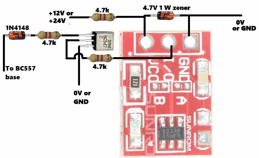
For the opamp circuit, replace both the 5V zener diodes with 12V zeners, and supply the TTP223 with a separate 4.7k/4.7V zener diode across its VCC pin, as done in the original diagram:
hello sir I know it’s been a long time since we talked I hope your are good and healthy i just wanna ask you a thing that! last time we fixed the all issues with the ttp223 but now if I install new one onto the circuit the whole story completely changes ! don’t know how I have tried several ttp223 but still all the responses were same the toggle function of the ttp223 couldn’t proform well it’s stays on whenever I touch it it’s bed how could I fix it ? i/o have 1k to the bc546 ! but still it’s not working at it should have to be !
Hello Neeraj,
Let us discuss the matter under the following article, please post your question here:
https://www.homemade-circuits.com/ttp223-capacitive-touch-module-explained/
sir it worked 🎉🎉🎉🎉🎉 after implantation of the 1k with the series of the i/o it worked seamlessly now I am testing it with every condition if I face any issues during testing I will tell you ! thanks sir 👍
this one sir
Ok, please disconnect the TTP223 and check it separately, connect an LED with resistor across its output and check its response to touching..
sir as you can see above of this comment this is the circuit we were working on last year and now I am getting issues with the touch module !!!!! I’m waiting for your comments please help me
Neeraj,
I have answered you under the TTP223 article, please discuss under that article.
Please post the exact image which you are discussing. Right click on the image and click “copy image address” and paste it in your comment…
That’s great Neeraj,
Let me know if you have any further problems with the circuit…
sir it doesn’t work at all even after replacing 1k and 4.7k and 10k the results were same as Before sir I have a little doubt if I push manually bd140 the circuit works and if I touch ttp223 is also works and led blinks whenever I touch it ! i checked the voltage across vcc and gnd pin of the ttp233 we got 5.4 v after the circuit was not before thats means if we wanna to operate this touch module as a push button then we have to make any changes so that we can get voltage to this module before we start the whole circuit! understood? can we connect the zener of this ttp223 directly to the input of the circuit? at the emitter of the bd140? as my assumption this will provide ttp223 5v and this ttp223 can start circuit! !
Neeraj, You are absolutely right, I completely missed that point.
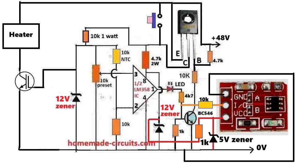
Yes the TTP223 module’s Vcc must be supplied directly from the 48V DC input so that its output can provide the triggering voltage to the BC546 base.
So, in the following diagram, please disconnect the TTP223 1k from the 12V zener diode. Then replace the 1k with 10k and connect it with the +48V supply, make sure the 5V zener remains connect across the Vcc and ground of the TTP223:
can we connect bc546 base with the ttp223 ? or with the copper plate ! ?
First confirm the TTPP223 capacitive touch distance with an LED, whether it works as per your your specifications or not, then we can configure it with the BC546. Copper plate will get triggered with other external RF disturbances, so it is not good.
yeah sir I removed the 10k resistor and then I checked voltage in gnd and i/o this whole ttp223 workes on 3v or 2.7 v and I got 2.5 v at the i/o pin should I connected this i/o directly to the bc546 base ??
Since we already have a 10k resistor in series with the VCC pin of the TTP, so it may be fine to connect the I/O output of TTP directly with the BC546, however I would still recommend using a 1k in series between th I/O and BC546 base.
Please check the results and let me know.
I have followed this circuit diagram!
You can modify it in the following manner:

If it has problems, try replacing the 1k associated with the 5V zener with 4.7k or 10k.
so can you show me the modifications on the diagram ? because of the diagram I can understand it easily please 🥺
You can try the following modified heater controller design with touch switch…..both the zener diodes are now 5v zener diodes:
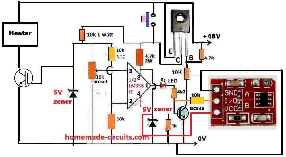
The ground side 1k resistor at the BC546 base must be replaced with a 4.7k resistor….
in simple terms can’t we reduce the input voltage for ttp223 to 3~5v and then directly connect it’s i/o pin to the base of bc546. it will be less complicated and also we can use power resistor to reduce voltage just like we did with our ic lm358 ! ????
That’s exactly what I suggested in my earlier reply.
You can connect the TTP223 output directly with the base of BC546 through a 10k resistor.
The +5V can be extracted directly from the opamp supply pin by replacing the IC zener diode with a 5V zener diode.
but how we can use simply with 10k resistor?
Sorry i did not understand your question…where do you want to connect the 10k?
but it’s too complex! can’t we make it more straight and simple?
sir now we are getting 5.4 v in the input of the ttp223 and still the circuit is not getting started because in the i/o pinout the voltage ttp223 is producing only 0.22v and this cause us ! if I use mannual option and monitor voltage at base of the bc546 then I got around 0.75 to 0.77v ! you have suggested me to connect 10k resistor at the i/o pin to base of the transistor if we monitor voltage at the i/o pin above the resistor we got 0.4v ! we need to trigger the bc546 then we need 0.7 v atleast! am I right?
Neeraj, Please disconnect the 10k from the I/O of the TTP and check the voltage directly between the I/O and GND. The voltage here should be around 0V in normal condition, and should turn 5V momentarily when you touch the TTP touch-pad.
If you are not getting 5V after touching the touch-pad that means your TTP has some problems, then you must diagnose the TTP separately.
Yes 0.7V is required to switch ON any BJT.
Actually the BC547 can be removed and the ttp223 output can be directly connected with the base of BC546 transistor through a 10k resistor…
It is the most basic configuration, and all the parts included in it are necessary.
last time i tested this circuit which you have provided me long ago !
with this ttp223 was able to work with my conditions also with 5mm thick plastic sheet!
Ok, then you can connect the 1N4148 end which is shown as “to BC557 base” to the base of BD140.
yeah sir it worked i have tested it with some distance!
Neeraj, please provide more information regarding how you tested the module?
Finally it worked both leds was working at 6v Max and I also connected 5v dc motor after replacing the leds motor also working super efficiently now I understood the whole work of the opamps thanks sir ji. Now what should we do next ?
That’s good Neeraj,
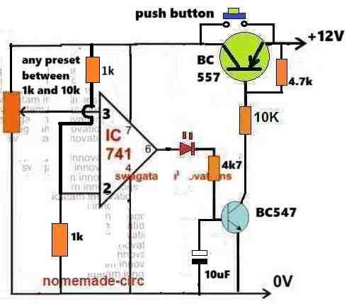
Now build the following circuit and test the push button action:
Congratulations sir we have made it 🎇
Everything is fine and working super efficiently and I have understood the function of the opamps so it is getting easy for me and I have also tested the latch function which is working so nicely now what’s the next step ?
That’s great Neeraj,
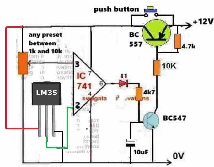
Now you can attach the LM35 at pin#2 of the opamp and check the results, as per the following diagram:
As you know, now if the LM35 voltage at pin#2 of the IC exceeds pin#3 voltage set by the preset, the opamp output will go LOW and the latch will break.
Suppose if you want the trip point to be at 80 degrees Celsius and if suppose at this temperature the LM35 output is 0.6V, then the preset voltage at pin#3 of the IC must slightly lower than this, maybe at 0.5V.
So when the LM35 output at pin#2 reaches 0.6V it will higher than pin#3 0.5V and the output of the opamp will go LOW breaking the latch and switching off the circuit.
We will use the relay afterwards once the above step is completed.
Sir I don’t know why all the time I am getting faulty lm35 i have bought them from different different retailers but still I got the faulty lm35 why ! I have also bought it from Amazon!
Neeraj, how are you testing it?
First connect the LM35 Vcc/gnd to +12V and -12V of a DC supply
Then heat the IC slowly.
Across output and gnd of the IC you should see voltage steadily rising from 0.1V to 0.7V.
Use the mV range of your meter or 2V range
I have tried same concept but I have found every ic is faulty! Some shows me fluctuating voltage and some shows me 0v also after heating up !
Ok, In that case you can try a 10k NTC instead….
But for 10k ntc we have to change the whole circuitry?
You can use the same circuit.

At pin#2 replace the upper 1k with your NTC.
Again at pin2, replace the lower 1k with 10k.
But what about the accuracy? And if I got a good lm35 then I will continue with it because I think it have a higher accuracy and for now I will use ntc for testing purpose! !!!!?
Yes, LM35 will have better accuracy.
For the time being you can try an NTC, by modifying the previous circuit, as described by me.
Sir it worked! now what’s The next step relay ? The input is 24v now so I think there will be no problem for the ic !
Neeraj,
Now connect a 24V relay coil directly across the supply terminals of the circuit (on the left side).
Remember to connect a 1n4007 diode across the relay coil. Cathode will go to positive side of the coil and the anode to the negative side of the coil.
Make sure you are using LM358 opamp for 24V operation. IC 741 will burn at 24V.
Sir relay worked but sometimes it’s a bit slow to off but now how can I use it for 48v heater ? Because now the input voltage is 48v and 8~7 amps ! How can we modify circuit in order to make it workable on 48v ! And also please suggest me which relay should I use for 48v contact rating ! ?
Neeraj, The slow switch OFF is due to the 10uF capacitor, you can reduce it to 1uF.
Connect the heater and the 48V supply with the 24V relay contacts as shown in the first article diagram.
Use a buck converter to step down 48V to 24V for supplying the emitter side of the BC557.
You can use a 48V 15 amp relay or any similar which suits your requirement.
But I don’t wanna use any buck convertor is there any way to implant something which can reduce the voltage for lm358?
If you use any linear regulator, it will become very hot.
Got an update after remaking all the circuit again I got the right things but still the leds didn’t light up! I checked the pin2 I got 6v and when the preset was little downward I got 4v or some in pin3 so thats means I got 0v at the output after turning preset I got 10.4v at the output but at the first led I only got 1.5v and at the second I got full 10.4v but the second one didn’t light up ! For now I got this results I will buy new lm358 tomorrow so let’s see what will gonna happen!
If the LED is not illuminating, then the LEDs could be faulty.
You can change the LEDs, or simply check the output with a meter.
Also make sure the preset is of good quality.
Try buying all the parts from amazon or ebay.
Sir here’s the explanation of the method which have worked for me : I have connected vcc to the 5v and ground to the ground and connected both pin2 and pin3 to the ground to see the voltage at the pin1 which is output and at the pin1 I got 0v so thats means ic is fine and now I connected the pin3 to the vcc and now I can see the voltage at the output is 5v now if we reverse it means now pin2 is connected to the vcc and pin3 to the ground now I got 0v at the output at the pin1
Is this method is right?
You must test it with a preset as shown in my previous diagram, otherwise we cannot proceed with any related circuit.
But my opamp worked with other methods! The same method I have mentioned in this link ! They have mentioned some voltage follower mode and other methods also and i found that useful please look at it
Neeraj, it should work in the basic comparator circuit in my previous link, without that we cannot proceed.
It is the foundation circuit for any opamp or a comparator IC.
Please try to learn how an opamp comparator works.
https://www.homemade-circuits.com/how-to-use-ic-741-as-comparator/
Sir I this comment is vanished this is the link of the article which I have found for opamp testing without testing circuit use http circuitdigest.com/comment/28421#comment-28421
Hi Neeraj,
If your opamp does not work with the following circuit then your IC is 100% faulty or your are doing something seriously wrong.
The following circuit is a simple comparator circuit and any opamp should work with this circuit.
If your opamp does not work in this circuit then I am afraid I cannot help you any further with any opamp related project.
Sir I have bought 10 (741ic’s) and I am also using another tester circuit for this ic’s because I don’t have trust on this ic that’s why I bought 10 of them lets see which one will work I will update you all the ic’s is from texes instrument! I will update you as soon as I got any update
That’s good, Neeraj.
Please try the following setup first to confirm your ICs (as explained previously), make sure to use an IC socket for the iC so that you can change the ICs quickly. Also, build the circuit by soldering and not on breadboard.
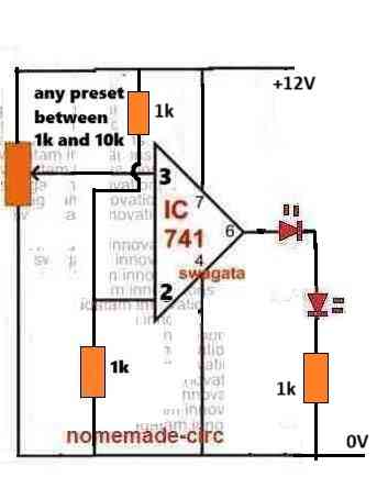
Use 5V to 12V DC as the supply, not above that.
Sir I am done with the 741ic I have bought 15 of them and not even a single one worked 😭 not even a single one I am done with it. I have doubts in building my circuit but after so many trys i am sure that my circuit connection is super fine but not the ic I have tried another circuitry for ic testing but still answer was the same the ic’s were faulty as always. Can we use another opamp ? Like lm358 because it’s more versatile and I have seen so many articles using same lm358ic if yeah then please suggest me tester for for the lm358 ic 🙏
Hi Neeraj,

Yes, if your 741 ICs are not working with the following basic setup then your ICs are definitely faulty:
For IC LM358, the pin3 and pin2 connections will be the same.
For pin#6, replace it with pin#1 of Lm358
And for pin#7, replace it with Pin#8 of Lm358
Sir lm358 have 2 opamps so it will be much better because if one opamps is faulty then I can work with the second one isn’t that !?
Neeraj,
please confirm with one opamp first using pin3, pin2 and pin1 of the IC. Make sure to connect supply pins also, pin8 (+Vcc) pin4 (Ground)
Sir can you please make a video on this circuit because whatever I do i fail all the time I am desperate right now please make a video on this circuit and how do you make it I wanna see it where is i am wrong because now I do everything right but at the end the results are same as before ? it’s my humble request to you please make a video on this circuit and also show me how to make it from scratch on your YouTube channel please because I have done previously so much works with circuits but this one is so simple but frustrating please make a video it’s my humble request and tomorrow is my birthday if this circuit won’t work tomorrow then I can’t celebrate my birthday happily !
Neeraj, a video is not required for such a simple operation. You are not not reading the steps and not discussing the results that’s why you are not able to solve it.
You have already confirmed that when you press the push button the 741 latches and the LED turns on, right?
Next, you just have to set the preset mid-way and touch the pin2 to positive for a second then remove, this should break the latch and revert the circuit to its original position, with LED switched off.
Yeah but today I was frustrated and i remade the circuit again but now the new circuit is not even functional for the push to on and the 741ic is not latching I have checked the all the connection but every connection was good but still didn’t got the result! Why ? Sometimes it’s works and sometimes it’s don’t why ? I am using all new components but still unable to make it happen why!
Please build it by soldering on a strip-board and then it should work. If you try it on breadboard it can be difficult to get the correct results. Use an IC socket when you build it on a strip board.
Sir I know the breadboard is not good that’s why I am using zero pcb which you have suggested me right now how can I upload pictures of our circuit on the comment section if I can then I will show you
Have you used an IC socket?
I can only suggest the steps and explain the functioning of the steps, beyond this i cannot do anything.
So a picture will not help.
The best way to troubleshoot is to understand the circuit working in a step wise manner, which I have already explained to you.
When pin2 voltage becomes higher than pin3, the output pin6 becomes 0V and vice versa.
Sir I was working on this circuit which is shown in the article and with lm385 and the voltage is 24v but the real thing is that the push button function is not working at all and when I connect this circuit to the power it’s directly went on and also it’s can’t even sensing the temperature and also the second led is not working at all
I followed the whole stages as described in the article
And still the circuit is not working also checked all the connection and everything is fine but still !
Neeraj,
I have added the necessary details in the article under “troubleshooting”.
Please follow the steps and test the circuit without a relay and with 12V supply first. Check the LED response at the output of the opamp.
Sir I did everything for the trouble shooting but nothing worked now I got both LEDs on but the issue is same as before there is no push button function is working and no temperature sensor at all after giving it power it’s went automatically on that’s all I also connected 1uf capacitor at pin3 of the IC to the ground! Also I am using UA741CN IC! -_-
Hi Neeraj,
Please note that 741 might burn if supply voltage is above 15V.
Try the following basic setup without relay, without LM35, and with 12V and first confirm the push button action:
Hey sir it’s working perfectly with 12.3v what’s the next steps!
Neeraj,
Now first check and confirm the working of the LM35 ic separately.
Connect its vcc pin to 12v, gnd pin to gnd and connect a voltmeter across it’s out pin and gnd….heat it slowly with soldering iron upto 70 degrees and check the voltage output, if the voltage increases proportionately, then your lm35 is OK, now you can connect it with opamp pin3 as shown in the previous diagram…and check the circuit as explained in the above article, make sure lm35 is cooled down before initiating the testing procedures.
sorry sir I know it’s been a whole month actually my grandmother was died and on the next week my grandfather also so I couldn’t test those lm35 but I have returned from the village so I tested the lm35 and heated it and connected multimeter’s ground to the lm35 ground and positive to the output pin of the lm35 but I got confused the voltage is increasing after heating it up but it’s too fluctuates ! the voltage at the output pin and gnd of the ic fluctuates so much that’s why I didn’t get the accurate results! what should I do now !
Hi Neeraj,
Please refer to youtube videos, you can find some good videos which shows how to test Lm35 IC. The output should rise slowly as long as the temperature rises, and as soon as the heat source is removed the output voltage should start dropping towards.
The range of the meter should be set to 2V or 1.5V.
The meter reading will fluctuate as the temperature is connected or removed.
Make sure you do not exceed the temperature above 100 degrees C.
sir I tried everything after testing push button function I connected the lm35 to the pin3 of the 741ic and heated it but nothing happened with the preset was turned up fully and the input voltage was 12v ! I bought 3 lm35 ic’s but got the same result! either the store owner is crock or my luck is faulty ! I don’t know ?
Neeraj,

It will work only if you do it with proper understanding.
LM35 must be connected to pin#2 of the new circuit which is suggested, not pin#3
The idea is simple, after pressing the push button the red LED will illuminate.
After this when Lm35 is heated it will create a rising voltage at pin#2.
As soon as the pin#2 voltage rises above the pin#3 voltage (as per the preset setting) the latch will break and the red LED will shut off, the transistors will shut off.
It is a simple circuit and should work immediately without much efforts.
Sorry sir but suggest me other temperature ic because I have tried 4 lm35 and nothing happened i have checked all the circuit again and again and did not found any miscommunication but still lm35 is not working as it should have to be suggested me another ic so I can complete our remaining work and after that if I visit outer market from the town then I will buy the good quality lm35 but for now suggest me other temperature ic! Please
Neeraj, if your LM35 output is not increasing from around 100mV to 700mV in response to temperatures from 30 degrees C to 100 degrees C, that means your IC is not good. If it does, then your circuit will definitely work.
Unfortunately there are no other equivalent type temperature sensing ICs which are commonly available in the market.
I would still recommend checking the LM35 separately and see whether the output increases from 100mV to 700mV or not…there are many youtube videos you can refer to.
Sir can you suggest me how to check the 741ic because after getting right lm35 the circuit isn’t working! I have taken every step carefully all the time but still unable to make it ☹️☹️? this is so bad it’s shameful for me because I can’t even make this simple circuit!
Hi Neeraj,

In the the following circuit, suppose you set the preset so that voltage at pin#3 of the IC is 0.5V. Now, when you heat the Lm35 if its output voltage at pin#2 of the IC exceeds the 0.5V then the output pin#6 will turn from 12v to 0V, turning off the transistors and breaking the latch.
Before the above operations you must press the push button to latch the IC 741 so that pin#6 is at 12V.
So basically when pin#3 voltage is higher than pin#2, then the output is high or at +DC supply level.
If the voltage at pin#3 goes below pin#2 voltage, then the output voltage at pin#6 becomes low or 0V.
Conversely, when pin#2 voltage is higher than pin#3, then the output is low or 0V.
If the voltage at pin#2 goes below pin#3 voltage then the output voltage at pin#6 becomes high or +DC supply level.
More can be found here:
https://www.homemade-circuits.com/how-to-use-ic-741-as-comparator/
Neeraj, the circuit is obvious and straightforward and will surely work, however it can be successfully completed only by proper understanding and proper setting up procedures. Tomorrow I will update the above article with the full step by step set up and troubleshooting procedures…please read it, understand it and go ahead accordingly…
Sir I have a one general question one of my friend asked me this question if I have 1 wire and I have 2 different loads first is 48v 360w with 7.5amps and second one is the 24v 360w with 15amps so can you tell me at which load this wire will heater up much faster ? At 48v or 24v ? Because the power is same but the amps is so different I am so confused ?
Hello Neeraj,
24V heater will burn if used with 48V, so it cannot be used. It will heat fast and burn or get damaged after some use.
It’s not about heater it’s about wire just simple copper wire
OK, sorry I misread your question. The wire will heat up more with the 24v load because it will pull more current than the 48v load.
And 48v is much more safer then 24v in terms of everything!
If all the relevant parameters are rated at 48V then 48V is better than 24 V in terms of power efficiency.
So power doesn’t matter
Power does matter, and it’s the current in the power which does the damage, so it’s the current which needs to be considered.
Hey have a one Little doubt can I use this circuit with 48v ?
You can use with modifications.
Sorry I am so needy but as we can assume 24v takes almost 15a in order to achieve 360w but on the other hand 48v needs only 7.5a for 360w and it won’t give much strain on the wire !
You will need a 48v coil relay for this, to avoid a regulator circuit, I hope that is OK with you.
So if I wanna switch from 24 to 48 then just change the relay ?
A few more modifications will be required, I will update the drawing tomorrow.
Which type of modification sir any suggestions!
I forgot to show a push-button between the collector/emitter of BD140, please insert a push button in that position.
It’s accuracy is same as this previous circuit?
Also please make sure to connect a 12V zener diode between pin3 of the IC and the ground line, to ensure that pin3 voltage never exceeds the pin7 voltage of the IC.
It is the same circuit as earlier except the voltage range which is 48V now.
And I can use lm358 IC instead of lm741
Yes 1/2 LM358 can be used, IC 741 will also work nicely.
Okay sir
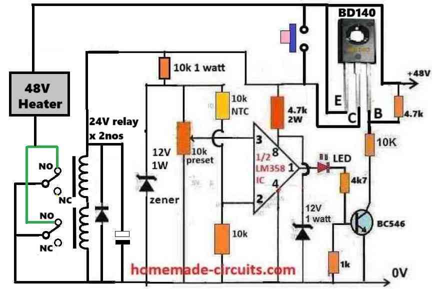
You can try the following circuit:
Remember this one ! You have made this for me it’s a 48v version! And this circuit need a little modifications! Please look at this ! And also we are now using lm358 so check it if you can make some modifications on it ! !!!!
Ok, you can try the following modified design which will work with 48V supply, relay and heater.
😊 I will update you soon but I have a doubt is there any need for the capacitor?
The capacitor at the BC546 base is not needed. I have replaced it with a 1k resistor, which is more effective.
However, if your relay chatters while switching OFF, you can add a 10uF capacitor parallel to the 1k at the base of the BC546.
So here’s the issue the latch is not working with bd140 ! And ic is getting 12v and if I connect one wire of the thermistor to the positive line then at the pin 2 I got 24v and more and at the pin3 i only got some 12~15v and If I connect thermistors wire to the 12v input of the ic then it works ! But still the latch is not working I have seen 46~48v at the base point of the bd140 but if I push the button then the push to on function is not even working! So it’s not latching nor its functioning like push button!
Neeraj, please try the following setup first to confirm latching. I have removed the relay here, we can connect the relay once the latching confirmed:
Sir latch didn’t worked circuit is not even getting started! And when I touched and hold the emitter and collector of the bd140 then I got voltage on the circuit! Also I am using 55c12 zener which produce 12v at 0.5w ! Is this gonna make issue?
Neeraj, in the following circuit which you are testing, the latch will work only when the pin#3 voltage is initially adjusted to be higher than pin#2 voltage.
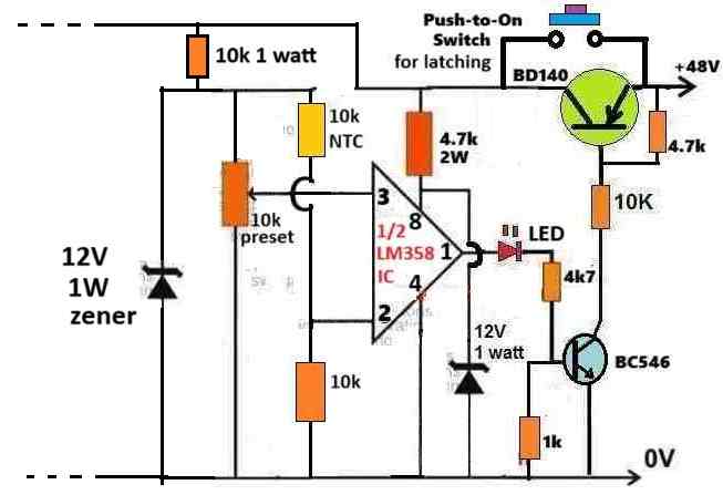
So keep the push button pressed and check the voltage at piin#3 and pin#2. Make sure pin#3 is slightly higher than pin#2.
It is i have checked it the pin3 voltage is higher then pin2 but still the latch is not working! Diodes are not the issue?
When you press the push button does the LED light up?
Nope but as I said you earlier i have to hold the bd140 and if I checked the voltage across leds terminal I got 11v or some ! But the led didn’t light up at any situation!
If the LED is not lighting up that means the IC pin#8 is not getting 12V supply, please check all these basic steps. Without power the IC will not work, the transistors will not work, the LED will not light up the latch will not work…
Sir can I have a testing circuit for the latch function testing? Because for now I have checked all the connection and components! But still the circuit is not latching! !
Neeraj,
the test setup is the same which I gave you earlier, without the relay, using two zener diodes.
Please follow the steps which I suggested earlier, check pin#8 voltage of the IC, check why the LED is not illuminating.
Sir now the led illuminated but now the issue is the push button function is not working bd140 is getting on when it connected to the input with even touching and thermistor is also working and same as before latch is not working like if I heat thermistor then the led will turned off and after the thermistor is cooled the led and whole circuit will turn on automatically! Latch function is not working and can you tell me I have connected bd140’s collector pin to the input and the base is pin3 and at pin1 is a emitter is connected to the circuit! Is this correct?
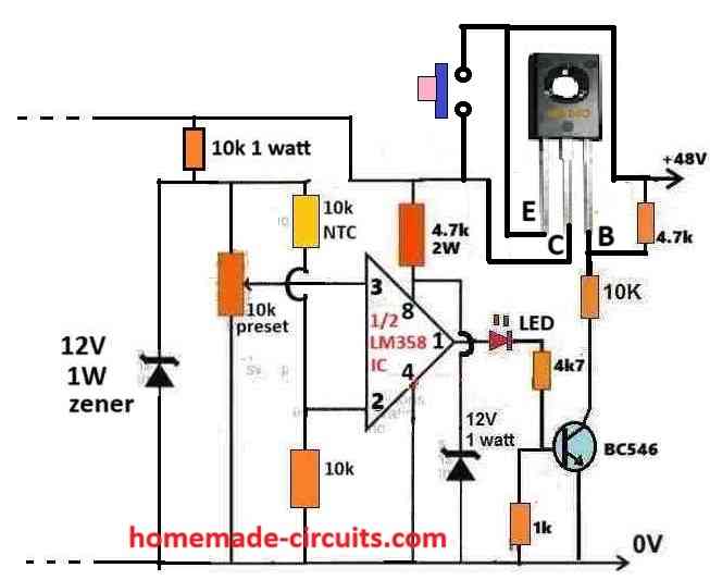
Neeraj, you can refer to the following diagram for the BD140 connection details:
Congratulations 🎉 sir we have made another successful circuit it worked last time the main cause was led and now I have changed it and now the circuit is working as it needed thanks sir for all of this ☺️ now what’s the next step?
That’s good news Neeraj, now you can connect the 48v relay coil with a parallel diode, as shown in our earlier diagram, and check the results by heating the thermistor with a soldering iron. Make sure to adjust the preset correctly.
Do I also have to add the extra diode and 10k resistor which we have added for testing circuit?
Yes, for 48v operation it should be exactly as shown in the following image, the dotted lines will go to the relay coil
Don’t forget to add a diode across the relay coil….
Sir how are you? I have a question can we use igbt or bjt instead of relays because I couldn’t find out any single relay which can work on 48v 360w or maximum 400w load I got one 48v coil voltage relay but after some use the relay melted a bit and I don’t consider it good for long term if there is any way to use igbt in this circuit the it might help us ! ? Reply me as soon as possible because I am going Market today if you suggest me a igbt then I will buy it now !
Hi Neeraj,
If your load is a 48V DC load then you can use a MOSFET or an IGBT.
So which MOSFET or igbt should I use and buy ? And how can I implant it in our circuit?
What is the ampere rating of your 48V heater?
Not more then 8A it’s a maximum ampere
Actually MOSFETs can be unpredictable devices and might get damaged without any clues….so I would recommend using a BJT instead.
You can try a TIP35 BJT it will work perfectly for your 48V 8A load
What about igbt ?
IGBTs are good you can use any 100V 20 amp IGBT
So which one will not require heat sink igbt or bjt ??
Both will require heatsink
Alright 👌 but as per my opinion the igbt will be better then bjt ! ?
Yes an IGBT is always better than a BJT.
So how can we implant it to the circuit and which igbt should I use for the operation
Any IGBT rated at 100V and over 20 amps will do the job….Once you buy the part let me know I will show you how to integrate it with the circuit…
MBR20100CT ? Can this igbt will work ?
That’s a Schottky Diode, not an IGBT
I have searched the internet but all I see is 1200v or 600v igbt ! Can you suggest me something?
Yes, IGBTs are mostly rated with high voltage, in that case you can try a 1000V IGBT such as FGA50N100BNTD
Sir this igbt that you have suggested me is not available on the market so I bought this one it’s a H20R1203 igbt it’s a 1200v 20a igbt can this igbt will work for us ?
Hi Neeraj, It should work according to me. You can try the following configuration:
Sir I know I am so demanding guy but can I use irf540 MOSFET for this circuit because it’s have 100v and 33a rating ! Because currently I have irf540 MOSFET!
Yes, you can use IRF540 MOSFET also, connection will be exactly similar to the IGBT diagram shown previously.
MOSFETs drain will go to the positive line of the circuit and source will go to the negative line and gate will be that same ??
….actually this circuit was designed for a relay operation by the input BD140 transistor…now since you are connecting the 8 amp load directly with the BD140 supply, this transistor will not work, it will burn.
You must replace the BD140 with TIP36.
What about MJE2955T instead of tip36? Can I use it ??
It is rated at 10 amps only, it won’t take the load….tip36 is rated at 25 amps
Yeah but the load is also 48v 8.5A !
You can try it and see if it works or not.
The drain will go to the positive through the heater load, not directly.
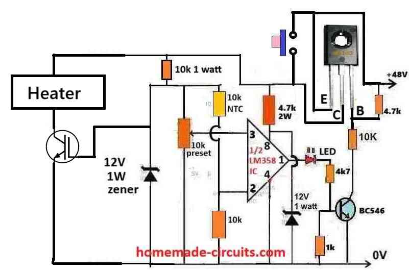
Source to ground
Gate to the 12V zener cathode.
Please refer to the previous IGBT diagram, the connections are identical, just replace collector with drain, emitter with source, and gate with gate.
Sir irf540n MOSFET is getting so hot within seconds at the load of 48v 7.5A ! Is there any other MOSFET is available which is suitable for our circuit?
Hi Neeraj, you can try the following MOSFET.
https://www.homemade-circuits.com/high-current-mosfet-irfp2907-for-wind/
Sir I have doubt can’t we use the same tip36c for heater because I think it’s more worthy then anything else! Because I couldn’t feel heat on it at the input! Can I use it also for output?
Neeraj, I had suggested you TIP35 in the beginning, but you said that you wanted to use a MOSFET.
Anyway, yes you can use the transistor TIP35 for operating the heater, not TIP36 because it is PNP.
For base resistor you can use 100 ohms 1 watt
Alright tip35c with 100ohm 1watt ?
Yes, TIP35c with 100 ohm 1 watt base resistor.
Sorry sir for the late my exam was on going btw I have bought tip35c with 100ohm 1watt resistor and now i am a bit confused about the connection 😕!
No problem Neeraj,
The TIP35 connection will be exactly identical as the IGBT connections which I had shown you earlier, just make sure to add the 100 ohm in series with its base.
Sir tip36c is unsuccessful it’s touch 100°c within seconds I can’t work on it !
Neeraj, are you referring to TIP35 or TIP36? I think tip36 is on the input side and tip35 is supposed to be on the output side with the heater…so which transistor are you referring to?
Sir after changing the emitters wire to the thik one it’s doesn’t made any difference still tip35c is heating Maddy!
Then I think a relay is the only option left, because all transistors will heatup. You will need a heatsink for all types of transistor.
Or you can try configuring the tip35 like a Darlington pair with 2n2222 and see how it works…this should allow to reduce the heat on the transistor.
Alright leave transistors now we only gonna work on relays but relay also have some issues like it’s chaters also maker noises when it is going on off stat and the pins also makes some sparks ! And finding 48v coil voltage relay in the market is very tough 😕 also 30v 10a DC load relay heats alot and sometimes melted also I have one 48v coil voltage relay with 28v 10a DC load this relay worked but the same issues gave me pain ! So now which type of relay should I need ! And what will be the coil voltage? And my load current is not that much it’s stay between 7.5 to 6A !
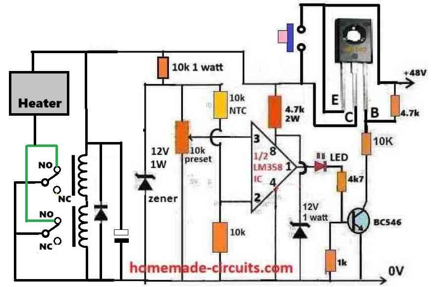
You can do one thing, take two 24V relays and put their coils in series, and contacts in parallel, this will solve all the related issues instantly.
To solve the chattering problem, simply add a 220uF/100V capacitor parallel to the relay coil (end to end across the series coils).
Don’t forget to put the 1N4007 freewheeling diode also across the relay coil…
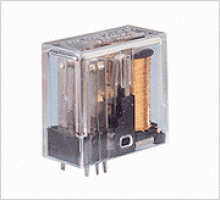
For the relays you can use OEN make 24V relays such as these:
So these relays are not available in 48v version?
It may be available but not everywhere, because there’s less demand for 48V relays compared to 12V and 24V. So 24V may be more easily available.
And I think using 2 relay in series won’t increase there current load capacity! ?
using 2 relay coils in series with parallel contacts will decrease coil current, and increase contact current capacity.
Couldn’t I use 2 normal 24v relays which have 5 pins in series?? It will be more easier then this relay! And also easily available to the market! What’s your thoughts?
The OEN relay is also an ordinary relay with 5 pins, but its quality is very good…you can use any other 24V relay 5-pin if you want.
So right now I have 2, 24v 15A relay they are generic and now how can I make connections! Can you show me with an image ? Because words are confusing me !
You have to wire the relays in the following manner:
Spotted a mistake in the diagram the heaters positive input should have to be connected to the emitter of the bd140 not at the collector of the transistor! Because bd140s emitter to collector continues current carrying capacity is not enough am I right?
You are absolutely right, here’s the corrected diagram:
Can I use OEN 26 RELAY 1 form A or 1 form C ? You can see it’s datasheet by searching oen 26 relay ! Please check the datasheet and tell me which one is better for me because these relay comes in both 48v and 24v version this also have 12A and 16A current carrying capacity oen dealer suggested me this relay ! Please check
You can use the 48V 12 A or 16 A both should work, because your heater load is 8A.
And 1formA have no NC pin should I go for it ?
without NC is fine, but 28V DC load restriction is not OK…
Like this calculation – 28v x 12a = 336w dc load capacity? And 28v x 16a = 448w and our needs is 48v x 7.5a = 360w I think both relay can work without any hassle! ?
You can check the relay practically, and verify if it works or not.
But every relay have the same dc voltage 28v max load rating and have difference between current and i remember when you said that voltage doesn’t matter much the current carrying capacity matters ! And power !
It is my assumption, I may be wrong, so it is better to confirm with the OEN dealer.
Sir I got an idea the relay will take time to deliver to my residence until then can we work with irf540n MOSFET? Because last time i used this MOSFET in our circuit it worked but since it’s got heated we decided to change it with tip35c but this transistor heated so faster then ever faster then MOSFET so in my opinion can we use 2 irf540n MOSFETs ? In this circuit I think they will heat less then ever? What’s you thought on this please tell me !
Hi Neeraj,
You can try two MOSFETs in parallel, it will be cooler compared to a single MOSFET.
Make sure to connect the positive side terminal of the heater directly with the +48V DC input.
Sir we made it we made it possible it worked after all this month’s we made it possible I have used 2 irf540n MOSFET in parallel and it worked and believe me the MOSFET heated so less that I can hold it with my bere finger it worked i have tested it with full load but I have seen a bit difference one MOSFET heated a bit higher then the other is that gonna make any issue?
Thanks Neeraj, glad it is working now using MOSFETs.
If one MOSFET heats up little more then it will proportionately start introducing higher resistance to the load current, so that the other MOSFET is forced to handle this extra current, so now the previous MOSFET starts cooling and the new MOSFET starts heating up…this current exchange will continue and the heat will be thus uniformly shared across the two MOSFETs.
So it won’t have any serious issues.
This is just the opposite to BJTs, because MOSFETs have negative temperature coefficient, meaning as it heats up, the current passage through it is reduced proportionately.
Still, if you are not sure, you can simply mount the two MOSFETs over a single common heatsink, very close to each other.
The accuracy of the thermistor is not good because sometimes circuit off at 80°c of the water temperature and on the next time it’s cut off at 77 or 75 ! I have sets preset and i didn’t touched it again but this type of accuracy is not good enough! Should I use lm35 because I can calculate voltage to temperature easily in lm35 but also most of the temperature ic I get were faulty!
Sure, You can try LM35 sensor in place of the NTC thermistor. Buy it from amazon or any other reputed online source.
But sir in this pdf you can see 1 form A relay is with 4 pins and it have 16a load rating and another 1 form C have 5 pins and 12a rating both have 28v dc load voltage which one should I choose?
I think 28V DC load specification will not work because your heater load is rated at 48V.
https://drive.google.com/file/d/1n_2OIa8tTKsc0tjydMkqcVWJUpoSFKe7/vie w
Remove the dash between view and link will be available
I have contacted oen relay dealer he told me there is one relay which can help me so can you check the datasheet! 1 form C and 1 form A which one should I consider both have 24v and 48v versions
The google drive link must be in the shared mode so that others can open it. Right now it is not in the shared mode so it is not giving me the access.
90% of the circuit is completed but the rest 10% is taking everything 😕
Well I am using tiny thin wire at emitter of this transistor does it can cause this issue? -_- because this tip35c should have to handle that much current without any hassle!
It should be thick wire otherwise the wire will not hold 8 amps and melt…The wire should be 2mm thick…
Oh sorry it’s tip35c !
Good morning sir 🌄 I have bought mp4560dn module 5v output but I ma confused at the input of this module because what is the meaning of the EN at the vin+ input ? Because when I connected + input and – input the module didn’t worked at the output I didn’t get anything! now should I have to connect EN instead of +input and -input ? I am confused! I am sharing the link of the module
Good Morning Neeraj,
Yes EN is the enable input.
Pulling this pin below the specified threshold shuts the chip down.
Pulling it up above the specified threshold or leaving it floating enables the chip.
Please read this datasheet pinout details carefully, everything is explained in this datasheet:
https://www.farnell.com/datasheets/3161503.pdf
Sir I have a question I have tried your lm2576 ic article and i tried the circuit which can be used for 40 to step down 5v or so but as I can see now it worked on 48v too but the real issue is that when I connected this lm2576 fixed voltage circuit to the relay i saw that at the input of this circuit I got 48v and it was dropping and I didn’t even on the circuit of the temperature control circuitry and when I did the input was fine but I didn’t got anything at the output then I got confused then I tried with 12v temperature control circuitry and the same thing happened! If I use this lm2576 circuit directly with the SMPS and the load is 5v dc motor it worked super efficiently! But then I did it with temperature control circuitry I didn’t got anything! Why ?I am using lm2576 5v fixed ic ! And a standard circuit which I have found on the datasheet of this ic ! Sorry I have written down too lengthy 😅
Hello Neeraj,
The maximum tolerable input voltage of LM2576 is 40V, so you must not exceed this limit at any cost.
Please provide the schematic link in which you are trying to use the LM2576.
This is the circuit
Not this, the temperature controller circuit in which you are integrating the LM2576…
This one
Is the above circuit operating normally as per our previous discussion, did you connect the relay and check?
Yeah I checked it the circuit is working super nicely 🙂 with relay !
Ok, but you cannot connect the LM2576 with 48V, you can use LM2576HV instead.
Sir I have bought lm2576hv 5v fixed and as I said earlier as soon as I turn on the temperature control circuitry the lm2576 blasts and the whole step down circuit stopped working it’s my second time 😭 but the small results can’t we use power resistor as we used for our temperature control circuitry to step down 48v to 12v or so ! Because all I need is a 5v Motor to be turn on with my heater at the output of the temperature control circuitry! Please sir do something!!!!!!
Hi Neeraj,
Resistor can be used to drop 48V to 5V but the resistor might dissipate a lot of heat.
Please provide the AMPERE specifications of your motor, I will try to calculate the resistor value.
The motor I am using is used in dvd so I don’t think it will take more than 2 amps !?
You can use Ohms law to calculate the resistor value;
R = (V_supply – V_motor) / I_motor = 48 – 5 / 2 = 22 Ohms
Power = R x I^2 = 22 x 2 x 2 = 88 watts.
Resistor will waste around 100 watts of power.
Alright so we can’t do that ? But idk how the lm2576hv is getting blasted everytime! This is how I connect the step down circuit to the temperature control circuitry positive input of the stepdown goes to the relays NO connection just like the heater and the nagative goes just like -48v directly is this ok I know it is but why ! And now how could we make something which can work!
Neeraj, the LM2576HV is a adjustable buck converter. Did you make it as per the instructions given in this article or its original datasheet?:
https://www.homemade-circuits.com/0-to-50-v-adjustable-switching-power-supply-circuit-using-ic-lm2576/
If yes, then your IC may be duplicate type and not original.
I think you should buy the assembled board from amazon, and then check its response.
Sir can you tell me which step down module is better for my needs ! mp4560dn module or XL7015 module ?
Which one should I choose?
Hi Neeraj,
The mp4560dn looks perfect for your application since it can supply 2A current as required by your motor…just make sure to buy a readymade preassembled tested module.
Which type of modification any suggestions?
Thats great but it’s with much more parts and I have a question does this circuit can work with 24v 15a 360w ? Directly? And how there is no transistor to operate the relay and can I connect 24v input directly?
Yes, you can use 24V directly with a 24V relay, but then the opamp will need to be from the IC LM358.
The relay is operated by the BC557 output itself.
Yeah but 24v relay is not available widely in the Market! So if I need 12v relay to be used then I have to add 7812 in the input of the circuit?
Sorry but I couldn’t understand the “opamp will need to be from the IC LM358”
You can use the circuit as shown with 12V supply and 7812 IC but then the 7812 will heat up a lot.
If you use 24V DC and 24V relay then the opamp should be from LM358.
There are two opamps inside LM358, use any one of them.
What about the connection of the lm358 ? And I have heard that this lm358 is more versatile then the lm741. Please confirm about its connections
Pin3, pin2 and pin4 will be as it is. No change required.
Replace pin7 with pin8.
Replace pin6 with pin1.
Yes, LM358 is more efficient than IC 741.