• Skip to main content
  • Skip to primary sidebar

Homemade Circuit Projects

Need circuit help? Post them in the comments! I've answered over 50,000!

Blog | Categories | About | Hire Me | Contact | Calculators-online
You are here: Home / Datasheets and Components / High Voltage Transistors BUX 86 and BUX 87 – Specifications

High Voltage Transistors BUX 86 and BUX 87 – Specifications

Last Updated on May 18, 2026 by Swagatam 1 Comment

In this article we are going to make an effort to understand the technical specs of the BJTs BUX86 and BUX87 which are high voltage complementary paired transistors.

Table of Contents
  • Introduction
    • Technical Specifications and Electrical Tolerances

Introduction

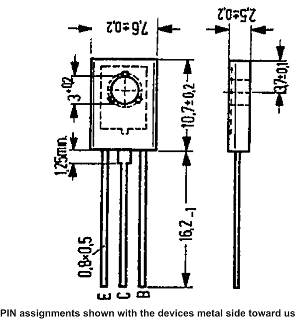
The Bux 86 and BUX 87 are typically high voltage switching transistors with silicon epibase. They come in TO-126 package and are NPN types.

These devices are especially known for their outstanding short switching characteristics and for having a high dielectric strength.

The main applications using these devices can be found with TV circuits, electronic ballasts, converters, SMPS power suppliers etc.

Technical Specifications and Electrical Tolerances

  • The maximum tolerable electrical parameters for BUX 86 and BUX 87 may be understood with the following points:
  • Maximum collector to emitter voltage for BUX 86 is 400 volts and 450 Volts for BUX 87.
  • Maximum tolerable collector current for is 500 mA for both the devices.
  • Maximum tolerable instantaneous peak current across collector and emitter is 1 Amp for <2 ms for both the devices
  • Maximum tolerable constant base current is 200 mA for both the devices.
  • Maximum peak instantaneous base tolerable current is 300 mA for both the devices.
  • Maximum power dissipation must not exceed 20 watts for both the devices
  • Typical Static characteristics @ 25 degree ambient temperature of BUX 86 and BUX 87 transistors are listed below:
  • Collector cut-off current is <0.1 mA
  • Typical forward current gain for both the devices is around 50
  • Collector to emitter saturation voltage is less than 1.5 V @ 100 mA collector current and 10 mA base current.
  • Base to emitter saturation voltage is less than 1 volts @ 200 mA collector current and 20 mA base current.
  • Maximum frequency handling capacity is 20 MHz for both the devices
  • Turn ON switching speed is 0.25 micro-second.
You'll also like:

  • spdtTypes of Switches, Working and Internal Details
  • AMS1117 1A LDO Voltage Regulator IC – 3.3V, 1.8V, 2.5V, 5V Regulators
  • 2n2222 1BJT 2N2222, 2N2222A Datasheet and Application Notes
  • 40ampdiode40A Diode with Reverse and Overvoltage Protection

Filed Under: Datasheets and Components Tagged With: BUX, High, Specifications, Transistors, Voltage

About Swagatam

I am an electronics engineer and doing practical hands-on work from more than 15 years now. Building real circuits, testing them and also making PCB layouts by myself. I really love doing all these things like inventing something new, designing electronics and also helping other people like hobby guys who want to make their own cool circuits at home.

And that is the main reason why I started this website homemade-circuits.com, to share different types of circuit ideas..

If you are having any kind of doubt or question related to circuits then just write down your question in the comment box below, I am like always checking, so I guarantee I will reply you for sure!


Previous Post: « How to Make a Remote Control Circuit from a Remote Bell
Next Post: How to Understand and Use IC 4093 NAND Gates, PinOuts »

Reader Interactions

Questions & Answers

Total Posts: 1
Newest Oldest
Florin MOINEAGU
June 19, 2025 • 1 year ago #181895

POTENTIAL PARTNERSHIP
WE ARE INTERESTED FOR AN ELECTRONIC MODULE TO LASER DIODE
ARRAY OR SINGLE

Reply

Need Help? Please Leave a Comment! We value your input—Kindly keep it relevant to the above topic! Cancel reply

Your email address will not be published. Required fields are marked *

Primary Sidebar


Categories

  • Arduino Projects (95)
  • Audio and Amplifier Projects (134)
  • Automation Projects (18)
  • Automobile Electronics (103)
  • Battery Charger Circuits (89)
  • Datasheets and Components (109)
  • Electronics Theory (150)
  • Energy from Magnets and Earth (40)
  • Games and Sports Projects (11)
  • Grid and 3-Phase (20)
  • Health related Projects (27)
  • Home Electrical Circuits (13)
  • Indicator Circuits (16)
  • Inverter Circuits (100)
  • Lamps and Lights (163)
  • Meters and Testers (72)
  • Mini Projects (28)
  • Motor Controller (68)
  • Oscillator Circuits (30)
  • Pets and Pests (15)
  • Power Supply Circuits (91)
  • Remote Control Circuits (50)
  • Security and Alarm (65)
  • Sensors and Detectors (107)
  • SMPS and Converters (46)
  • Solar Controller Circuits (62)
  • Temperature Controllers (44)
  • Timer and Delay Relay (50)
  • Voltage Control and Protection (44)
  • Water Controller (37)
  • Wireless Circuits (31)


Circuit Simulator

circuit simulator image


Subscribe to get New Circuits in your Email


Other Links

  • Privacy Policy
  • Cookie Policy
  • Disclaimer
  • Copyright
  • Videos
  • Sitemap

People also Search

555 Circuits | 741 Circuits | LM324 Circuits | LM338 Circuits | 4017 Circuits | Ultrasonic Projects | SMPS Projects | Christmas Projects | MOSFETs | Radio Circuits | Laser Circuits | PIR Projects |


Recent Comments

  • Swagatam on Pure Sine Wave Inverter Circuit Using IC 4047
  • Budai J on IC 556 Pure Sine Wave Inverter Circuit
  • Johan on Pure Sine Wave Inverter Circuit Using IC 4047
  • Swagatam on How to Build a Simple Egg Incubator Thermostat Circuit
  • Swagatam on Ultrasonic Pest Repellent Circuit

Social Profiles

  • Twitter
  • YouTube
  • Instagram
  • Pinterest
  • My Facebook-Page
  • Stack Exchange
  • Linkedin

© 2026 · Swagatam Innovations