• Skip to main content
  • Skip to primary sidebar

Homemade Circuit Projects

Need circuit help? Post them in the comments! I've answered over 50,000!

Blog | Categories | About | Contact | Calculators-online
You are here: Home / Datasheets and Components / IC 4063 Datasheet, Pinout Working, Applications
IC 4063 pinout

IC 4063 Datasheet, Pinout Working, Applications

Last Updated on March 3, 2023 by Swagatam 2 Comments

The IC 4063 is a CMOS-based 4-bit magnitude comparator IC that can compare two 4-bit binary or BCD numbers and determine which one is greater than or equal to the other. It operates on a supply voltage range of 3V to 18V and is compatible with TTL logic levels.

Table of Contents
  • Features:
  • Electrical Characteristics:
  • Pinout Configuration:
  • Pinout Explanation
  • Applications:

Features:

Some of the key features of the IC 4063 include:

  • Wide supply voltage range: 3V to 18V
  • Low power consumption
  • TTL-compatible inputs and outputs
  • Operating temperature range: -55°C to 125°C
  • Output current capability: 10mA
  • Output voltage swing: nearly rail-to-rail

Electrical Characteristics:

Some of the key electrical characteristics of the IC 4063 include:

  • Supply voltage range: 3V to 18V
  • Input voltage range: -0.5V to VDD + 0.5V
  • Input current: ±10mA
  • Output voltage range: 0V to VDD
  • Output current: ±10mA
  • Propagation delay time: 180ns typical (for VDD = 10V)
  • Quiescent current: 6μA typical (for VDD = 10V)

Pinout Configuration:

warning message: electricity is dangerous, proceed with caution

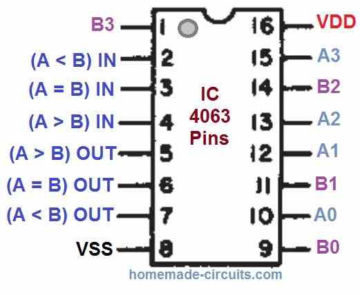
The IC 4063 has a 16-pin dual in-line package (DIP) as shown in the above pinout diagram:

Pinout Explanation

The IC 4063 is 4-bit magnitude comparator chip which is normally used is computers and logic circuits. In these applications, the IC 4063 calculates and finds out whether or not a 4-bit word (Binary or BCD) is equal to, less than, or greater than a subsequent 4-bit word.

You will find 8 pinouts in the IC 4063 which are assigned for the comparator functions. These pinouts are A0 (pin#10), A1 (pin#12), A2 (pin#13) A3 (pin#15), B0 (pin#9), B1 (pin#11), B2 (pin#14), B3 (pin#1).

The IC 4063 also includes 3 inputs for the cascading function. These are pin#2 (A < B), pin#3 (A = B) and pin#4 (A > B).

The above 3 inputs facilitate the developers to upgrade the comparator functioning of the IC to 8, 12, 16, or up to 4N bits.

If you want to cascade the inputs of a single IC 4063, you can do it in the following manner:

  • (A < B) = Low,
  • (A = B) = High,
  • (A > B) = Low

In order to process words that are longer than 4 bits, multiple IC 4043 ICs could be cascaded by hooking up the outputs of the less significant comparator with the relevant corresponding inputs of the more significant comparator..

For example the 3 inputs (A < B) = Low, (A = B) = High, (A > B) = Low, from a least significant IC 4063 should be connected to low, high, low logic in the cascaded system.

Applications:

The IC 4063 can be used in a wide range of applications that require the comparison of two 4-bit binary or BCD numbers, such as:

  • Digital counters
  • Arithmetic circuits
  • Control systems
  • Instrumentation
  • Data acquisition systems
  • Communications systems

You'll also like:

  • 1.  EGS002 Datasheet, Circuit Diagram Explained
  • 2.  TL494 Datasheet, Pinout, Application Circuits
  • 3.  BJT 2N2222, 2N2222A Datasheet and Application Notes
  • 4.  IC 4027 Datasheet, Pinout Working, Application
  • 5.  IC IR2184, IR21844 Half-Bridge Driver Circuit Diagram, Datasheet, Working
  • 6.  IC 4040 Datasheet, Pinout, Application

Filed Under: Datasheets and Components Tagged With: 4063, Applications, Datasheet, Pinout, Working

About Swagatam

I am an electronics engineer and doing practical hands-on work from more than 15 years now. Building real circuits, testing them and also making PCB layouts by myself. I really love doing all these things like inventing something new, designing electronics and also helping other people like hobby guys who want to make their own cool circuits at home.

And that is the main reason why I started this website homemade-circuits.com, to share different types of circuit ideas..

If you are having any kind of doubt or question related to circuits then just write down your question in the comment box below, I am like always checking, so I guarantee I will reply you for sure!

Previous Post: « IC 4049 Datasheet, Pinout Function, Application
Next Post: IC 4069 Datasheet, Pinout Working, Applications »
Subscribe
Notify of
guest
guest
2 Comments
Inline Feedbacks
View all comments

Primary Sidebar

circuit simulator image

Subscribe to get New Circuits in your Email

Categories

  • Arduino Projects (90)
  • Audio and Amplifier Projects (132)
  • Automation Projects (17)
  • Automobile Electronics (101)
  • Battery Charger Circuits (83)
  • Datasheets and Components (105)
  • Electronics Theory (140)
  • Free Energy (37)
  • Games and Sports Projects (11)
  • Grid and 3-Phase (19)
  • Health related Projects (25)
  • Home Electrical Circuits (12)
  • Indicator Circuits (15)
  • Inverter Circuits (89)
  • Lamps and Lights (142)
  • Meters and Testers (71)
  • Mini Projects (46)
  • Motor Controller (64)
  • Oscillator Circuits (28)
  • Pets and Pests (15)
  • Power Supply Circuits (89)
  • Remote Control Circuits (50)
  • Security and Alarm (64)
  • Sensors and Detectors (103)
  • SMPS and Converters (29)
  • Solar Controller Circuits (59)
  • Temperature Controllers (42)
  • Timer and Delay Relay (49)
  • Transmitter Circuits (29)
  • Voltage Control and Protection (38)
  • Water Controller (36)

Other Links

  • Privacy Policy
  • Cookie Policy
  • Disclaimer
  • Copyright
  • Videos
  • Sitemap

People also Search

555 Circuits | 741 Circuits | LM324 Circuits | LM338 Circuits | 4017 Circuits | Ultrasonic Projects | SMPS Projects | Christmas Projects | MOSFETs | Radio Circuits | Laser Circuits | PIR Projects |

Social Profiles

  • Twitter
  • YouTube
  • Instagram
  • Pinterest
  • My Facebook-Page
  • Quora
  • Stack Exchange
  • Linkedin
  • Recent Comments

    • Swagatam on How to Convert a Low Power Inverter to a High Power Inverter
    • Swagatam on Simple Buck Converter Circuits using Transistors
    • NGANG on How to Convert a Low Power Inverter to a High Power Inverter
    • Swagatam on Make this 7 Segment Digital Clock with Beep Alert Circuit
    • Swagatam on Make this 7 Segment Digital Clock with Beep Alert Circuit

    © 2025 · Swagatam Innovations