It is possibly the smallest LED flasher to date, which is able to flash an LED ON/OFF infinitely using a single transistor, a resistor, and a capacitor.
Can you imagine making a great looking LED flasher or blinker with just a single transistor and a couple of other passive parts?
That's exactly what I have explained in this post! This is perhaps the world's simplest and the tiniest LED flasher you can get!

How it Works
I came across this phenomena some eight years ago (2006), accidentally, while trying to make a smallest possible motorcycle side indicator flasher, and was surprised by the phenomenon.
However, then I realized that the phenomenon was already discovered by Mr. Dick Cappels while investigating the negative resistance theory in BJTs by the Japanese researcher Mr. Reona Esaki (Aka Leo).
Reona Esaki's thesis work in the relevant field and on tunnel diodes ultimately won him the Nobel Prize in 1972.
That looks too good to be true, however the following diagram will simply prove that it's really possible to create a working LED flasher circuit using just one general purpose transistor as the main component.
At that time, I was unaware that this was occurring as a result of the transistor's negative resistance characteristics.
The circuit actually exploits the negative resistance factor in transistors to produce the blinking effect.
I'll be soon writing a comprehensive article on this and we'll see there how the concept can be modified in many different ways.
Parts List for the proposed single transistor LED flasher circuit
- R1 = 2K7,
- R2 = 100 Ohms,
- T1 = BC 547,
- C1 = 100 uF to 470 uF
- LED = Any Type, any color
The flashing rate could be varied either by changing the value of R1 or C1 or both together. But the supply voltage not be less than 9V otherwise the circuit might fail to work correctly.
You may also love to read this article: Blinking LED Circuit using LDR
Circuit Diagram
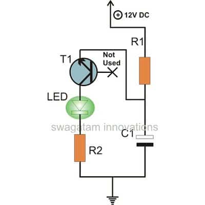
Calculating the LED Flashing Frequency
You can use the following formula for approximately calculating the LED ON/OFF blinking rate
Frequency (f) ≈ 1 / (2.1 * R * C)
Where:
- R is the resistance in ohms
- C is the capacitance in farads
This formula gives us a rough idea of what the flashing frequency might be. But the actual frequency can be affected by a hand full of different factors, for example like the specific components you are using in the circuit, the voltage of the power supply and also the temperature.
To adjust the flashing rate:
- Increase the resistance (R): If we make the resistance higher, it will take longer for the capacitor to charge up which means the flashing rate will be slowed down.
- Decrease the capacitance (C): On the opposite side, if we lower the capacitance vaalue, the capacitor will charge up faster causing the flashing rate to speed up.
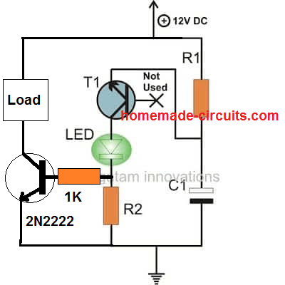
Connecting an External Transistor for Higher Loads
Video Clip:
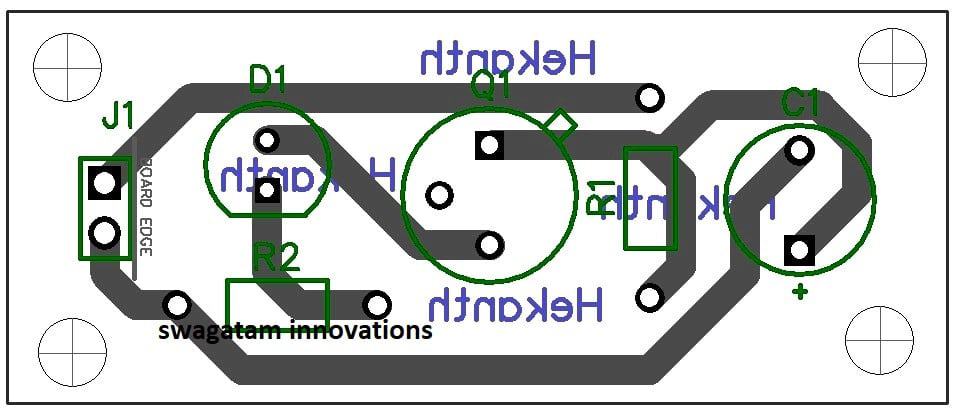
PCB Design
Circuit Basics
In this circuit we are using one NPN transistor which is BC547, one electrolytic capacitor of 330 uF, two resistors of 2.7 k and 100 ohm, and one LED, and supply voltage is +12 V.
Here the LED is connected in the collector path of transistor, while the base of the transistor is not connected directly to the supply, but instead it is controlled indirectly through the RC network made by the 2.7 k resistor and the capacitor, and this indirect base control is the main reason why oscillation becomes possible.
Start Condition When Power Is Applied
When power is applied then the capacitor is in a fully discharged condition at the start, and because the capacitor is empty at this moment, current immediately starts flowing from +12 V supply through the 2.7k resistor into the capacitor.
At the same time a small voltage slowly begins to appear across the capacitor and this rising voltage also starts appearing at the base of the 2N2222 transistor, but the transistor still remains in the OFF state because the base voltage is not yet high enough.
Capacitor Charging Action
As time passes, capacitor continues to charge slowly through the 2.7 k resistor and because this resistor limits the current, voltage rise at the capacitor and at the transistor base is gradual and not sudden
When the base voltage reaches around 0.6 V to 0.7 V then base-emitter junction of the transistor becomes forward biased, and at this point the transistor suddenly turns ON.
LED Turns ON And Rapid Discharge
When the transistor turns ON then collector current starts flowing through the LED and 100 ohm resistor, and because of this current flow the LED lights up.
Now the important thing happens because the transistor in ON state provides a very low resistance path for the capacitor, so capacitor discharges very quickly through the base-emitter junction and through the transistor itself, and this fast discharge is the key feature of the Esaki oscillator.
Transistor Turns OFF
As the capacitor discharges rapidly, then base voltage falls sharply.
When this base voltage drops below the required base-emitter threshold then the transistor immediately switches OFF.
When the transistor switches OFF then the collector current stops flowing and the LED also turns OFF, and circuit returns back to its initial condition.
Cycle Repeats Continuously
When the transistor is OFF again then capacitor once again starts charging slowly through the 2.7 k resistor, and this slow charging followed by sudden discharging keeps repeating again and again.
Because of this continuous repetition the LED keeps flashing ON and OFF as long as the supply voltage remains connected.
Why This Circuit Is Called Esaki Oscillator
This type of oscillator works because of non-linear behavior of a semiconductor junction, mainly the base-emitter junction of the transistor.
And the sudden ON OFF action caused by fast discharge of capacitor creates a behavior that looks similar to negative resistance effect observed in tunnel diodes, which were studied by Leo Esaki.
That is why this simple single-transistor relaxation oscillator is often referred to an Esaki oscillator.
Flashing Speed Control
The flashing speed of the LED mainly depends on the RC time constant formed by 2.7 k resistor and 330 uF capacitor, so when the resistor value is increased then the capacitor charges more slowly and LED flashes more slowly.
When the capacitor value is increased then OFF time becomes longer and flashing rate reduces, but the 100 ohm resistor does not affect oscillation frequency because it is only used to limit the LED current and protect the LED and the transistor from excess current.
Why This Esaki Oscillator Does Not Work At 5 V Or 6 V
Now we see this circuit works fine at 9 V or 12 V but when we try at 5 V or 6 V then the circuit stops working or works very weak.
The reason is simple, the voltage becomes too low for this type of oscillation.
When we give supply then the capacitor must charge and push voltage to the base of the transistor but the transistor base-emitter already needs around 0.6 V. And the LED in the collector also needs voltage to conduct, and the resistors also eat some voltage.
So now when supply is only 5 V or 6 V then very little voltage is left for proper action.
So the capacitor charges very slowly and also cannot reach a strong enough level and when the base voltage reaches near 0.6 V then the transistor only turns ON very weak, not strong.
Because of this weak ON condition the capacitor cannot discharge fast and without fast discharge the oscillation cannot happen properly.
When the transistor does not switch sharply then the circuit stays stuck in between ON and OFF and the LED either stays dim or does not blink at all. This is why at low voltage the circuit fails.




Questions & Answers
i used all the components shown and it didn't work the first time. it works now because i changed out the transistor until the led started blinking
congrats!
Can any TV remote control the circuit
you can try this one:
https://www.homemade-circuits.com/2011/12/make-yourself-simple-led-flasher-at.html
What are the formulas to calculate the timing of the flash?
t = -log((V-Vc)/V)R*C
To calculate Vc at a specific time, the formula can be modified to:
Vc = V-(V*exp(-t/(R*C)))
I am trying to imitate cloud to cloud lightning using the smallest possible circuit. I found this project that uses only the flashing LEDs and a battery…www.youtube.com/watch?v=Rj5tqhGypAE&feature=player_embedded. I found 3mm flashing LEDs …lighthouseleds.com/led-component-lighting/animated-leds-flashing-blinking/3mm-led-flashing-round-top.html
Can I power 2-3 of these (amber and/or white) using one CR2032 battery? Can I get them to flash at different rates? …I think that may drain the battery too quickly since there are no resisitors used, is that correct?
I am trying to imitate cloud to cloud lightning using the smallest possible circuit. I found this project that uses only the flashing LEDs and a battery (Candle Flicker Hair Bow). I found 3mm flashing LEDs (3-3.4V, 20mA, 1 Hz flash frequency)
Can I power 2-3 of these (amber and/or white) using one CR2032 battery? Can I get them to flash at different rates? …I think that may drain the battery too quickly since there are no resisitors used, is that correct?
you can include a 22 ohm resistor in series with the LEd in order to make the battery drain slower.
alternatively you can employ a joule thief circuit for making the batt last for ages.
a flashing LEd could have an automatic flash rate changer built-in, so it could go on changing the flash rate by itself.
hi my name is madhu i want electronic variable wattage choke circuit diagram for flurocent tube. pls send to the mail below
email: madhubabu.sv@gmail.com
sorry, presently I do not have this circuit.
HI
will this circuit work for 16v?
yes…
I want to design a LED Flasher Cirrcuit with Input : 9V-16V, On time : 0.5s +/- 10%, Period : 1s +/- 10%, Reverse polarity protection : required can you help me with the above circuit? Will it work for this conditions?
need your response
thank you
the above circuit won't be appropriate, search for:
transistor astable multivibrator circuit …..or 555 astable multivibrator circuit
Can you tell me in technical prospectivem, why cant we use this circuit??
the above circuit is not configured in a conventional manner so could have limitations in terms of interval setting accuracy…you can try it out, though.
Hi,
thanks for your prompt response.
Could you Just modify the circuit for this specifications LED Flasher Circuit with Input : 9V-16V, On time : 0.5s +/- 10%, Period : 1s +/- 10%, Reverse polarity protection required, by using any other stage of RC or any other way. Using astable multivibrators is cost effective for my project, need a simple circuit. Hope for your response.
Thanks in advance
It will need to be tweaked and verified practically for those results….there are no formulas for it.
Hi, can you please tell me how the transistor is activated without the base connected?
In the circuit, the capacitor is charged by R1 until the voltage becomes large enough to get the emitter-base junction to avalanche which lights up the LED and also discharges the capacitor to trigger a fresh cycle….it basically takes place due to the negative resistance characteristic of the BJT
Hey buddy,i have installed 12v3led strip in my bike and i need them to blink.i knw i can use this circuit but what all i need to alter?to adjust speed and to power led 12v..
Mukesh you cannot use the above circuit, instead you can try any of the following designs:
https://www.homemade-circuits.com/2012/01/how-to-make-any-light-strobe-light.html
Please reply soon thnkx:-)
Hi Swagatam, were you able to write the comprehensive article explaining how this works?
Hi Siddarth, sorry no I could not complete it due to lack of time and other more complex assignments…you can Google "Esaki single transistor flasher circuit" to learn more about it.
Nice bro I am satisfied with this ckt. Can you please help me to blink some more faster
thanks bro, just decrease the value of C1 to make it blink faster
Hi Mr swagatam,
Can you guide me to make an automatic switching for my led emergency light using Transistors? I have connected 50 no's of led and planned for 6V/4.5 Ah battery.pl explain with circuit diagram.
Hi Mohan, you can refer to the following circuit and do it accordingly for getting the required results:
https://www.homemade-circuits.com/2011/12/how-to-make-efficient-led-emergency.html
how to test transistor emitter Base collector
Hi, how could I make this circuit flash twice every second like a police or ambulance vehicle?
Sir Swagatam,
Can I use this circuit as replacement for my turn signal flasher on my motorcycle? or is there another circuit you can refer to me..
As a 12v signal flasher for 12v led light.
Thank you very much..
Paul
Paul,
it may be possible, but you will have to add an additional BJT buffer stage for powering the lamps.
Thank you for your response sir.. How can i accomplished that? Can you please show me a circuit diagram with BJT circuit that i can follow sir..
Thanks again sir..
Paul, I’ll explain you verbally:
In the above circuit, remove the LED and join R2 directly with collector of T1, but make R2 = 1K
now take a TIP127 BJT, connect its base directly with the above junction of R2 and T1 collector, join its emitter with the +12V line…and connect the collector with the bulb…bulb other end will go to the ground line…I hope you understood.
Hi Swagatam,
I have seen it’s possible to make this LED stop blinking by disconnecting the capacitor. Is it possible to disconnect / reconnect the capacitor by means of an additional transistor on the cap side of the circuit? I would like the LED to be on then when the second transistor gets signal the cap is connected and flashing starts. I’ve achieved this with relays but as I will have many of these in my circuit the cost of relays isn’t a good choice.
Thanks for an excellent website!
Thank you Theuns, yes that may be possible, but instead of modifying the C1 section, I would recommended you to configure the ground supply line of the above circuit with an NPN such that when the NPN is triggered the circuit gets activated. For this you may connect the collector of the NPN with the ground line of the circuit,and the emitter with the supply negative.
Ha! If I did not see the video i would not have believed it.
Does not work in simulator.
http://www.falstad.com/circuit/circuitjs.html?cct=$+1+0.000005+12.050203812241895+53+5+50R+656+160+656+80+0+0+40+12+0+0+0.5g+656+464+656+528+0r+656+160+656+256+0+2700r+656+464+576+464+0+100162+576+352+576+464+1+2.1024259+1+0+0+0.01t+384+336+576+336+1+1+0.00012985325697745242+-0.30249585765328524+500w+576+320+576+272+0w+576+272+656+256+0209+656+256+656+464+0+0.00033299999999999996+0.8571050617707789+1o+4+64+0+4099+0.625+0.00009765625+0+2+4+3
that’s exactly why I never rely or use simulator softwares, they are no match for an human brain.
Considering simulators like LTspice can easily simulate op-amp and power supply circuits, it should easily be able to simulate your circuit, but try as I might, I too cannot get it to simulate.
BC547 A, B or C ?
LED: which one did you end up using (what breakdown voltage, forward current, partnumber…)
When only BC547 is written it means any BC547 can be used since the supply voltage is only 12V, in the video you can see that the LED is a 5mm 20mA type.
A simulator may have difficulty in simulating because the circuit works with unconventional principles.
I have a switch with implemented LED which is extra connected to minus. Is it somhow possible to get the LED flashing while switched on? I had to connect this circuit somehow after the LED on the negative pol.
If it is a 12C DC then You can probably try this circuit
https://www.homemade-circuits.com/how-to-make-single-transistor-led/
Hi sir,
1)In above circuit,can the blinker time be adjusted.(like “ON” for 1sec and “OFF” for 1 sec.).
And instead of led,how can i connect transistor which can act as a switch.(the transistor switch will be “ON” for 1sec and “OFF” for 1sec.)
2)The circuit diagram is shown in the link below
https://drive.google.com/file/d/10bVfTV6iDspl3Ma76lMcr33gFKMPpgy8/view?usp=sharing
how to adjust the blinker time ((like “ON” for 1sec and “OFF” for 1 sec.).
And instead of led,how can i connect transistor which can act as a switch.(the transistor switch will be “ON” for 1sec and “OFF” for 1sec.)
Thank you
Aakash,
I have updated the required diagram in the above post, you can check it out!
Sir,
How can i adjust its blinking time?(.(like “ON” for 1sec and “OFF” for 1 sec.)
Thank you
By using different values for R1, or C1. But it may not be too accurate
Sir can you please tell me the value of r1 and c1 for “OFF” 1sec and “ON” for 500Msec or 1sec.
Thank you sir for your kind reply and patience..
Hi Akash, I don’t have the formula for calculating the values, the best way to find is by some trial and error. Try 470uF for C1 and see if that produces 1 second ON/OFF
Thanks a lot sir..
Awesome u’ve made my day
How to connect only 2n2222 directly without LED diode and resistor R2. 2n2222 case is TO-92 or TO-18?
You can try replacing the LED with a direct link!
Did you mean this change? https://drive.google.com/open?id=1hWoMbVoXlW7XV_cBq9DYQzzY7w3ybYl8 You did not tell me 2n2222 case is TO-92 or TO-18?
Yes that’s correct, the package doesn’t make any difference!
Thanks Sir.
The circuit only when I touched the base of bc547 transistor. Otherwise it is not working. Why?
May be the transistor is not good, or there may be a connection fault… please recheck everything carefully.
yeah i had same issue. i had a high load led so after fiddling with capacitors and resistors – had to use 500Ω and 1KΩ resistor and changed caps from 100 – 470uƒ to get working.
Hi! Great tiny circuit! Will it work with 24V DC supply? If not, what changes have to be made? Thanks a lot!
Hi, Thanks, I am not sure whether it will work with 24V or not, but you can give it a try. The only change the circuit might need for this is the resistor, which could be increased to some higher value such as 4k7
Is there a circuit simulator that I can use to reproduce the same results? I’ve used many and none of them work.
It doesn’t work. How will current go from collector to emitter without the base current?
Good day Swagatam,
Awsome circuit, I’m trying to make a flashing led circuit like this but need it to activate on contact with water, do I simplify add a transistor to circuit so base closes on contact, if so where in circuit and how to incorporate a joule thief into circuit. If you have such schematic it would be much appreciated.
Thank you jonathan, you can modify the design in the following manner
For a joule thief circuit you a refer to the following post:
https://www.homemade-circuits.com/1-watt-led-driver-using-joule-thief/
Thanks so much, very new to electronics and programming, this will help alot, what is minimum voltage it will work with.
You are welcome, the minimum operating voltage is 9 V.
Ok sir
Thanks for the information. ????????
Hello Swagatam, Awesome circuit repo here.
Two things: —
1) I need an exact circuit as Jonathan but with the opposite effect. I need the flashing LED when there is “no contact” in water i.e ‘no signal’ from water. Meaning, when the water-tank is empty I need the alarm [buzzer and LED both to blink] on, but when there is water in the tank the circuit should not make any noise!. Being a newbie myself in the field I can’t seem to make any head or tail to reverse the signal effect in this circuit. May be I can use the ‘not used’ base pin of T1 for the purpose? I thought if there is any signal/pulse to T1-base then the LED would be off totally, but it doesn’t, why not? How can I do this?
2) If I need to get a buzzer to go ‘beep’, ‘beep’, ‘beep’ … continuously and parallel/alternative to LED until there is a signal on the T1-base, I presume the buzzer can go parallel to the LED in circuit?
Can you please point me to a direction to solve? I’d really appreciate any help.
Thank you N Syed,
You can probably try the following design:
for better response please connect another 1K resistor between the base and emitter of T2.
Yes you are right, you can connect a piezo buzzer in parallel with the LED for getting the required beep beep sound.
Dear Sir, i done it using bc 548 and working fine. Let mw know how to connect a high watt led eg. (3wattx3 series) to flash in this way or to use a 12volt relay instead of the led?
Dear Aju, please see the second diagram, you can the replace the LOAD with your LED, make sure to add appropriate limiting resistors with the LEDs, and also replace the 2N2222 with TIP122
Dear Sir,
I had used a mosfet 80to3gp and put high load. Its working fine. I have Doubt that whay resistance should i use in across gate ?
for MOSFeT gate resistance may not be required, so you can safely replace the 1K with a short link.
Dear Sir,
How to obtain a positive output in higher load connection? (in the collector Point of 2n 2222)
You can connect a TIP147 to the collector of 2N2222
sorry changing duty cycle may not be possible in this design
Dear, I am looking for a simple time delay circuit using this flasher for a 12 volt relay operation, the LED should glow stable once the relay is on. Thank you
Connect the positive voltage from the relay source with the collector of the transistor, or the anode of the LED
I need a circuit for a 5v led flasher using power from a USB cable.
Just to point out to people, that if you can’t get the transistor mentioned, the more common 2N3904 (included in a lot of starter kits) will do just fine.
If I want to run this Strobe effect on 3V ? is the same circuit or I have to change specification of Resistance capacitor
No, this circuit will not work with 3 v supply, it will need a minimum of 9 V too operate correctly.
Thank you Swagatam for your post. It is as cheap as recommended for my applications. I’m looking for a circuit that lights up a 10watts (or more) led lamp as the night comes in and turn off as the night comes out. It’s easy to find out this kind of circuit but the ones that uses relays to turn on and off the loading but what I need is a circuit that operates in fading mode, increasing charge in ascending way to lights up in the evening and decreasing charge like the morning comes to produce effects like a gradually lightening and dimmering the lamp.
Could you suggest me something to help, please?
Thanks a lot.
Gleiner.
Thank you Gleiner, you can try the following concept for implementing the specified slow fade action of the lamp in response to dawn and dusk.
Can this circuit be modified to run on a 1.5V or 3V coin cell battery? If no, why, and if yes, how?
Unfortunately, the above circuit cannot run on voltages below 9 V. The transistor requires at least around 9V to conduct using the indicated configuration
thank you!
I like the part where you included the diode
I found a circuit driving 10 LED with 4.5V battery using a Henry HR706 but can not find any info on the HR706. Is it just NPN transistor or more ?
The circuit uses the HR706 to drive the LEDs to flash every second or so.
The circuit has a 10 ohm resistor from the Base to Gnd, E (?) to LED and C (?) direct to +4.5V. Other side of LED is tied to 4.5V.
There’s indeed no online information about HR706, so it is difficult to tell whether it is a transistor or IC.
I need your assistance or advice on which transistor circuit diagram I can use to suit my needs. I need a circuit diagram which takes action e.g blinking the LED when base voltage is supplied and blink LED when base voltage is removed.it can have either 1 or 2 output terminals for signal.
That looks a bit difficult. Blinking an LED with a base voltage applied is possible, but blinking it with base voltage removed looks difficult…can’t figure it out right now.
Thanks for responding! Who do you think can help with such idea?
I don’t seem to have anybody in my contact who would do this for you…. maybe some knowledgeable person visiting this page is able to throw some light on this.
Like the unusual circuit! So many references to “simple LC flasher circuit” on internet, but nothing found. Where to find a tiny circuit to flash LED string?
Please provide the specifications of the LED string? I will try to suggest a suitable circuit.
Specifications are difficult to find. The strips are mostly available in 12V, 300 LEDs, available batteries are 5V, time on is 300ms, frequency is ~2HZ. So the circuit has to boost the voltage. The operation period will be <2 minutes usually. I have some BTA16 800B if they can be used.