This programmable timer can be used for switching a load ON and OFF with two sets of time delays, which are programmable from 2 seconds to 24 hours independently.
The delay timings are adjustable according to the users personal specs. The ON time delay and the OFF time delay are independently settable and this facility becomes the most important feature of a programmable timer circuit.
Using Versatile IC 4060
In this page I will elucidate a very simple yet reasonably useful timer circuit diagram whose ON time and OFF time settings are independently adjustable through ordinary pots.
The idea becomes so easily configurable due to the versatile IC 4060 which require minimal number of component for getting the unit running.
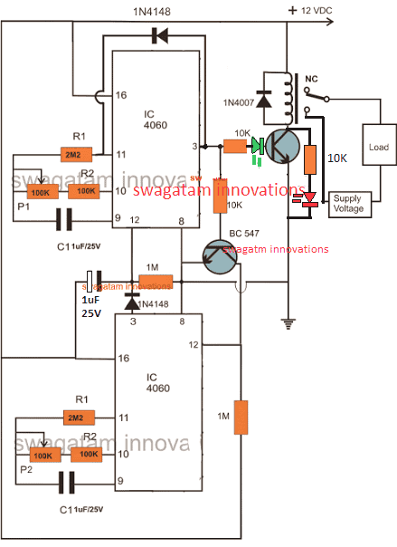
Looking at the CIRCUIT DIAGRAM below we can see that two inexpensive IC 4060 have been wired up as two independent timer modes.
However though the timing settings are independent for the two sections, these are coupled with other such that their initialization become very much interconnected.
Basically both the configurations are similar and have been rigged in the standard counting modes of the IC 4060 devices.
You may also want to make this Arduino based programmable timer circuit
How the Circuit Functions
The output of the upper IC is coupled to the reset input of the lower IC via a transistor in such a way that once the upper IC's output goes high, it triggers the lower timer into operation.
The lower IC then starts counting and when its output goes high, it halts the upper ICs counting and resets it to its original state and the process is initiated back from the start.
It simply means that as long as the upper ICs timing does not lapse the lower IC remains idle, however once the upper ICs timing lapses and its output becomes high, it switches the output load as well as the lower ICs operation.
The pot associated with the upper IC can be used for determining after how long the load will be switched ON, while the pot associated with the lower IC is used for determining how long the load remains in the switched ON position or simply after what time it should be switched OFF.
Update:
The LED positions have been changed in the following updated designs, because the earlier LED positions were conflicting with the relay operations, and therefore the positions have been relocated for ensuring foolproof operations.
Circuit Diagram of a Versatile Programmable Timer
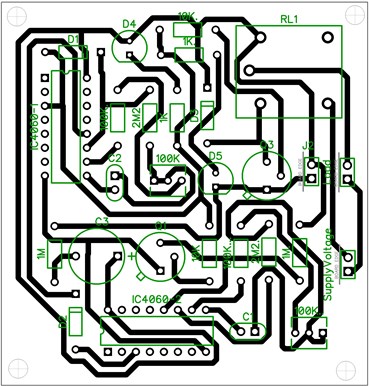
PCB Layout
Video showing the proposed 2-stage programmable timer circuit with LEDs
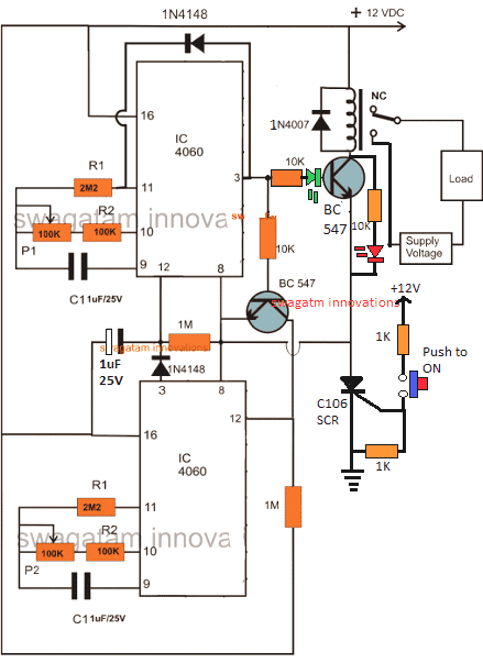
Using a Start Push-Button
The above design could be upgraded with a push-button to facilitate a push button start. This further ensures that the timer shuts off completely in case a power failure occurs while the circuit is operational, which in turn ensures that crucial loads like heater, or geyser are completely turned OFF during such situations.
Calculating RC Timing Components
It can be done through a formula, but the manual way is much simpler and accurate. It can be done as I have explained below:
- Connect any arbitrarily selected resistor above 100K in place of P1/R2 in the upper circuit.
- Switch ON and carefully note down after how much time pin#3 of upper IC 4060 becomes HIGH. This will be your "sample delay".
- Once this is noted, the other desired time delays could be calculated using the following simple cross multiplication:
Sample Delay / Desired Delay = Selected Resistor / Unknown Resistor
For example if you find the pin3 becoming high after 300 seconds, this becomes your sample delay value.
Now, we have the sample delay and the resistor value responsible for this delay.
Therefore if we assume the desired delay to be 1 hour or 3600 seconds, we can calculate it by substituting the values in the previous equation:
Sample Delay / Desired Delay = Selected Resistor / Unknown Resistor
300 / 3600 = 100 / x (unknown resistor)
300x = 360000
x = 1200 k or 1.2 Meg
This shows that 1.2 Meg in place of the P1/R2 will produce the required delay of 1 hour at pin3 of a IC 4060
Please note that the above calculation is only an example and the values do not indicate the actual results.
Customizing the Above Concept
This circuit of a flexible programmable timer circuit I have explained in this article was designed by me in response to a request by Mr.Amit. Let's know more about the request and the circuit details.
Technical Specifications
I need a circuit for my aquarium where it should do the following:
It should switch off the lights at 10:00 pm and start at 7:00 am daily + switch off the light at 12:00 pm daily and switch up at 6:00 pm back.
This will help to make my fishes live longer. 🙂
Thanks in advance.
Amit desai
The Design
So here's the circuit that I came up with. As the name suggest, the timer is pretty flexible and may be adjusted to produce any desired time periods, according to the above requested format.
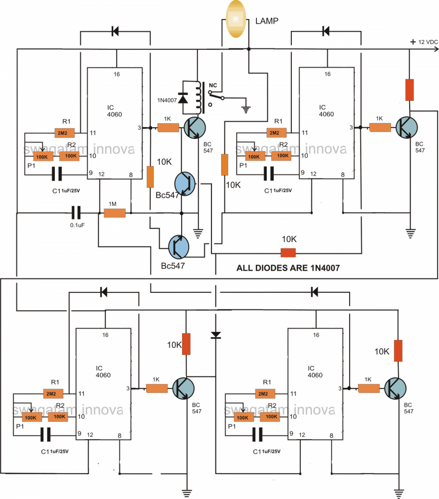
The circuit consists of four identical stages, made up of the IC 4060 timer configuration. Te timer sequence begins from the IC at the top left corner.
When power is switched ON this IC starts counting. Depending upon the setting of its pot, the IC triggers after a certain period og time interval.
This switches ON the relay and the driver transistor BC547 which consequently switches OFF the connected lamp. The stage gets latched with the help of the diode connected across its pin 3 and pin 11.
The above triggering also switches another BC547 transistor which connects the reset pin of the next IC 4060 to ground which initiates this stage also.
After a predetermined time, this IC also triggers its output at pin3 and gets latched by the corresponding diode, however this actionsends a feedback signal to the relay driver transistor, instantly switching it off and restoring power back to the lamp so that it lights up again.
Just as the above actions, the sequence further proceeds and switches ON the third IC 4060 in the line which counts the set time interval and pulls the relay back to OFF position via the diode connected to the collector of its bc547 transistor, such that the lamp again gets switched OFF.
As soon as the above triggering happens the last section at the bottom right corner switches into action and counts as per the setting of the respective pot, until the ICs output becomes high, this high reset the the first IC and switches ON the lamp once again so that the process may be restart the cycle all over again.
The pots may be increased to 3m3 for generating higher time interval periods, so is true with the respective capacitors.
Circuit Diagram
How to Adjust and Set Up
The timer may be adjusted as per the sent request, in the following manner:
If we consider the first timing sequence to begin at 7am and end at 12pm, means the upper left timer's P1 needs to be adjusted such that it activates the relay and switches off the relay after exactly 5 hours.
For keeping the lamp switched OFF in the above position and switch it ON back at 6 pm we now adjust P1 of the upper right timer section such that its output triggers after another 5 hours. This switches ON the lamp again.
The above situation needs to be kept intact until night 10pm, which is about 4 hours of period, therefore we adjust the lower right timer's P1 to get it triggered after 4 hours of time interval.
Finally, for initiating the above procedure back again the next morning at 7am, P1 of the last timer at the lower right is adjusted such that it resets the first timer after 9 hours..... and the cycle repeats.
For making the circuit work according to the above specified timing pattern, after adjusting the respective hours, the unit should be powered or switched ON exactly at 7 clock in the morning....rest will automatically follow.
Cascaded Programmable Timer Circuit with Multiple Outputs
If you are looking for a programmable timer circuit having multiple outputs for controlling multiple loads and with individual time settings, then the following circuit will do the job for you.
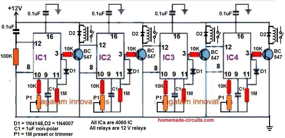
Here, a 4-step programmable timer circuit is shown, but you can add more number of 4060 stages to increase the number of cascaded outputs, as desired.
The time delay output of each 4060 timer stage can be individually adjusted and set using the relevant P1 preset.


Questions & Answers
can you please make a circuit which will turn on led for 10 seconds and then turn off for 10 minutes
You can try the concept which is explained in the above article using IC 4060. Let me know if you have further questions.
Buna ziua domnule.In diagrama de mai sus cu cele două 4060 programabil timer circuit, unde pot pune led pentru clipire ca în video.Multumesc fiți binecuvantat
Gelu, You can put the LED between pin#14 and ground, or pin#15 and ground, through a series 1k resistor.
Hello once again.
I must apologize to you. My first request on the programmable circuit at 2 o’clock I L’ai formulated while I had not read this second page yet. would you not consider this first request?
Joseph
Thanks
No problem Joseph, Glad you found the right post for your specific application!
hi sir, I want to 5v power supply and 1 day 2 times timer ( 6:00 am switch on to 6:15 am switch off ), (4:00 pm switch on to 4:15 pm switch off ).Please support circuit diagram with ic4060 for me.Thank you.
Hi Min,
It will require a combination of 4060 IC and 2 or 3 ICs of 4017….but still the timing durations might not be accurate.
Thank you for publishing your design. I am an electronics tech myself, and after a number of hours repairing things on my bench, I tend to leave and forget to turn off my desoldering station or power supplies.
So what I want to do, is use a circuit that has a start button , that closes a relay for an adjustable length of time, say 2-4 hours. Then opens and saves my Hakko desoldering station or my power supply’s from being on all night… or days.
A reset button would also be helpful, as some times I am down in the shop for longer than 2 hours.
Your thoughts?
Sure, that makes sense.
Here’s a simple design which will fulfill your requirement perfectly:
You can increase the timing range by increasing the value of C1 appropriately to higher values, but it should be a non-polar capacitor only.
Please ignore the previous design and use the following instead:
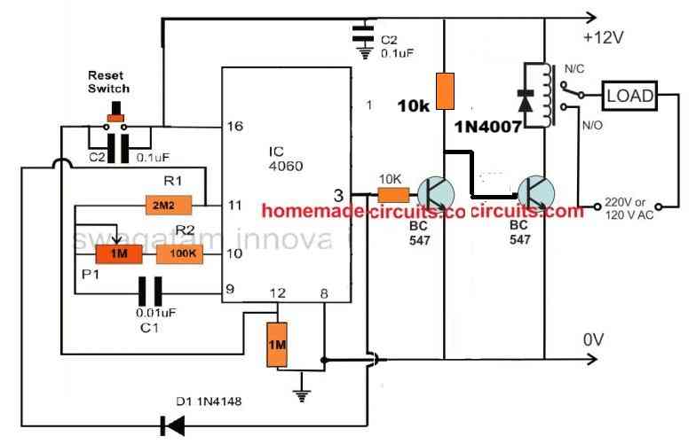
The capacitor c1 can be a 1uF/50V or higher, non-polar type.
Hi dear swgatam
Me need minimum 500 milisecond.
R1,R2 and C1 what tobe
Thanks
Hi Ismail, for a single timing output you can use a 555 timer instead.
Dont single,ı want 1 munite off 0.5 sn on for filter cleaning valve.
In the article I have provided the method to calculate the part values, please follow that procedure, you should be able to identify and select the right parts as per your specification.
Thanks dear you Are perfect
Thank you, it’s my pleasure!
Sir, Thanks for yu patience in replying. I have got a request. I am using bore well motor having starting capacitor and running capacitor and i want to automatically switch it on. As you know that once power is given starting capacitor will be in closed circuit for 3 to 5 seconds and should disconnect after that. Is there any simple circuit which can replace the function of push button presently used?
Thank you Ravidran,
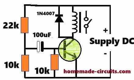
To keep the capacitor of the motor energized for a few seconds you can try implementing the following circuit:
The relay N/O contacts must be wired in series with the capacitor connection.
The 100uF capacitor and the 22k resistor values can be experimented to change the delay period as required.
The transistor can be a BC547 transistor.
This is the first time i am getting a guidance on a u tube chennal. Thanks for your quick response. I have started assembling cycles timer using CD 4060 published by you. I will make it success with your support. I do have some project. Pl share your email id.
Thank you Ravindran, i will try to help you as much as possible until you succeed.
We can comfortably discuss through this commenting platform so that other readers are also ale to go through our discussion and learn more about the subject.
Its better for me if you mention transister pin nane, like emiter collecter and base, i want to leqrn, i already maked for delay off for qs long i want, but problem is its not automatically on after 3 or 4 hrs, ppease support me……
You can checkout the BC547 datasheet below and compare the pinout details:
https://www.homemade-circuits.com/quick-datasheet-of-bc547-transistor-45v-100ma-npn-transistor/
Hello sir, hope all is going well. Sir i need your kind support. O want to diacuss about timer on and off circut. Sir can you give me a favor plz. Can you guide me resiaters, caposter valies as per cd4060 ic pin configration timing? Lile pon no 3 is for 8 to 24 hrs. Which resiaters and caposter value and pot value we have to use for same timer plz
Thanks in advance
Hello Ghulam,
There’s no accurate formula to calculate these values. You will have to find it yourself with some trial and error and using the cross multiplication formula given in the article. Please follow the steps provided under the title “Calculating RC Timing Components”
Hello sir, sorry to disturb you again. Sir, I am facing an issue in timer circuit. It works fine for almost 2 or 3 days, but after 1 or 2 or 3 days randomly it gets stuck on delay off section. I chose pin no 1 of CD4060 for delay and pin 3 for on time. 2 capacitors 22 uF as a polar capacitor I used on pin 9, 100k on pin 10 with 500k pot, and pin 11 used 2.2 mega ohm 2 resistors in series. While working, it worked fine but got stuck some time on delay section. Please guide me why it happens?
Hello Ghulam, do not use polarized capacitors. Please use only non-polarized capacitors. You can use 22nos of 1uF/100V PPC capacitors in parallel to get an equivalent 22uF non-polar capacitor.
Sir thanks for reply. Sir can i put 5mm led with 100ohm resister for pulse on pin no 7 for both ics seperatly? Or of there is any other way plz guide me
Ghulam, pin#7 will produce very fast pulse, which cannot be distinguished on the LED, instead you can use pin#15 or pin#14. Use 1k series resistor.
Its more easy if you make vedio on breadboqrf for me please.its request sir plz
Please don’t try on breadboard because breadboard can have loose connection problems, build it on a perfboard by soldering.
Dear sir, i want yo make timer for 20hrs load on and 4 hrs off. This cycle work automatically daily. Plz support me with simple diagram plz
Hello Ghulam,
The diagram is already given in the above article. You can try the first diagram.
However please do not attempt this circuit if you are a newcomer to electronics.
This circuit is recommended only for those who are reasonably expert with electronic circuits
Thanks for reply, sir i tried and its work for same time on and off, like only almost 10 seconds its on and off, i changed the resister values and pot to 1 m woth pin 10, but same. If i will not try then how i will learn, plz guide me b3cause i want to learn…..as i told you i alreqdy maked for delqy off as i want. With accurate time, but after load off not comes on automatically, i need solution for that load will on after our setting time. Plz
Hello Ghulam, The first circuit in the above article is a tested design and it worked for me perfectly.
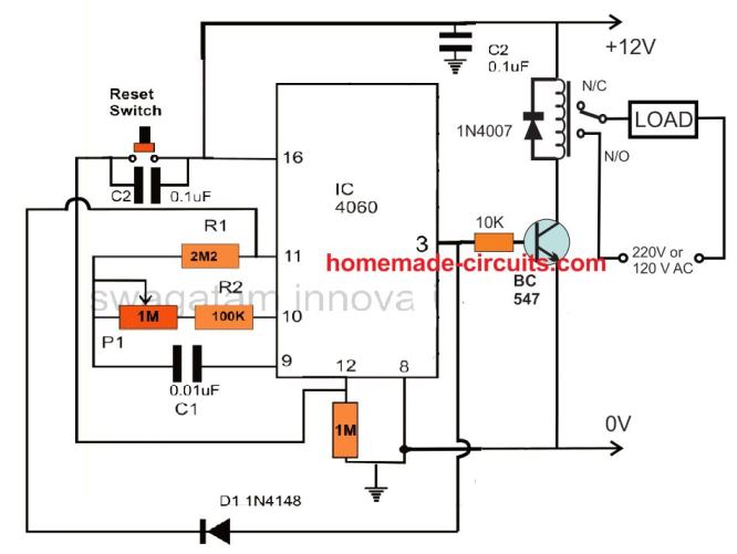
If you are confident that you can build it then you can try the circuit step-wise. First build the upper 4060 IC stage with the BC547 and the relay as shown in the following example design. If you succeed with this, then you can add the lower 4060 stage to it and check how it works:
Yes sir i tried and this uper circut is working, now how to add 2nd ic, can you make seperate diagram plz,
Ghulam, The diagram is already given in the above article. Please see the first diagram and see how the lower IC is configured with the upper IC.
Hi sir, lot of thanks for your support. now its working, thank a lot
That’s great Ghulam, glad it is working now.
Thanks for your passion to guide me…….if some one have good teacher like you then nothing is impposible. I cleared impossible mistion due to you. Thanks a lot
You are most welcome Ghulam, Please keep up the good work!
Can I use your above circuit to switch on at 6.30pm and switch off at 10.00 p.m. please?
Yes, that’s possible but the timing will not be accurate always.
Hi Swagatham
Can you please send me the circuit of the 4060 IC timer circuit for a 1 to 2 hours or more for time delay relay OFF
Hi Val,
Here’s the link you are looking for.
https://www.homemade-circuits.com/how-to-make-simple-versatile-timer/
Great article, Swagatam. I’m not too au fait with modern electronics, so please bear with me.
I’m basically wanting to switch an ultrasonic mister, powered via a mains transformer giving 24v rated at 1.0amps, on and off every 5 minutes or so (still experimenting) to control humidity in a small enclosed space I’ve constructed for a plant.
It appears to me that this circuit would do the job, but I’m unsure of several things which I hope you’ll be able to answer for me
ie what type of relay to use, what range of resistor values would you suggest I use as I’m starting from scratch, and whether It’d be feasible to tap into the 24v supply for the mister to power the circuit, using some form of voltage reduction (simple series resistor perhaps?).
Could a potentiometer be used in place of experimenting with various resistors, as the timing is not millisecond precise, and what range would you suggest please?
Thank you Peter,
If your ON/OFF time are equal and there’s no need of trying the above explained complex 4060 circuits. You can simply achieve it using a IC 555 timer circuit as explained in the following article:
https://www.homemade-circuits.com/alternate-switching-relay-timer-circuit/
You will only have to experiment with the 470uF capacitor for getting the 5 minute ON/OFF delays for the relay.
Please ignore the second load connected with the relay….you can use only one load as desired by you.
All resistors are 1/4 watt 5% CFR
Thanks for your prompt reply, Swagatam, and I appreciate you directing me to the other circuit.
However, as I’m still experimenting with timings, I think I would prefer to have the versatility of choosing different times for the on and off periods, so feel.
So could you please advise accordingly?
OK no problem, here are the answers to your previous questions:
Resistors are all 1/4 watt 5% CFR
Relay can be any 12V SPDT relay with a coil resistance between 200 ohm to 400 ohm.
To extract 12V from 24V supply , you can use a 7812 voltage regulator IC.
You can use a potentiometer only for P1 and P2 and vary the time delays as per the adjustments.
Thanks again. As I have no resistors in stock, I was hoping for some guidance on what values to purchase in order to achieve my aims. Alternatively could I substitute P1/R1 and P2/R2 with 1meg linear pots (+/- 20%) to achieve my aim, or would that not be high enough (the largest value I’ve found so far is 2M2 with a +/- 30% tolerance above 1M).
As I said, I’m not too familiar with modern electronics, but would it simply be OK to take the output voltage direct from the regulator (it has a tolerance of 2 to 4%) without any extra components?
All advice greatly appreciated.
You can replace the components at pin#10 of the IC with a 1M pot and a 10K series resistor. With C1 = 1uF you can get significantly long delays at pin#3 of the IC with these values at pin#9 and pin#10 of the IC. The remaining resistor values can be as is.
If you have good filtered DC input at the input side of the regulator then you do not have to add any other components at the output of the regulator. With a 24V input and 12V output your regulator can get very hot, so a heatsink may be required for it.
That’s excellent – thanks! As far as the 24dc supply goes, all I know is that it’s a standard mains direct plug-in transformer with 24v 1a rating made in China. Not sophisticated, but could it do the job? If not, any suggestions welcomed.
No problem, you can check the output of your adapter with a meter to confirm whether it is a pure DC or not. If it is a DC then the 7812 regulator will require no additional components for its configuration. Hopefully it should be an AC to 24V DC adapter
Yes it is 12v dc, so I guess I can go ahead!
Thankyou so much for your prompt answers and patience in dealing with my relatively basic queries!.
You are welcome, I am always glad to help!
Can I use the IC4060 timer circuit shown here only to turn a small electromagnet on and off for specified and adjustable millisecond periods of time? An example table is below. Don’t need quite the high accuracy indicated here.
Time (milliseconds)
On Off
1.09 | 28.91
0.55 | 14.45
0.36 | 9.64
0.27 | 7.23
0.22 | 5.78
0.18 | 4.82
0.16 | 4.13
0.14 | 3.61
0.12 | 3.21
0.11 | 2.89
Yes that’s possible. You would need two 4060 ICs for that. However adjusting to the milliseconds could be very difficult.
Hello Swagatam,
I’m glad it all cleared up, no harm was done.
From what I’ve read, one of the biggest disadvantages of transformerless power supplies is that they don’t protect the circuit they feed from electrical interference of any kind, without adding additional electronic components, which are either expensive or hard to find, end up increasing the complexity of executing a circuit.
Since it is a circuit with ICs and for better protection, I would like to ask if it would be possible to supply your circuit (using the TRIAC version) with a 230V/9V/1.5 VA transformer, as I have found a lot of them in emergency luminaires that have all been replaced by LEDs, and whose circuits are all functional. Do I need to rectify, filter and stabilize this power supply before feeding it to your circuit?
How would the 2 electrical diagrams look like?
Thank you in advance.
Best whishes,
Thank you Joao,
If you don’t wish to have a transformerless power supply, then the configuration woud become like this:
To this circuit you can supply a 12V DC from a transformer power supply with a full bridge rectifier and a filter capacitor or from an SMPS unit. The negative of the power supply will connect with the line that is marked with the ground symbol (line connecting the pin#8 of the ICs).
The bridge rectifier can be build using 4 diodes, and the filter capacitor can be a 1000uF/25V. You can include a 7812 IC for stabilization if you have one, which will ensure better working of the circuit.
Hello Swagatam,
In the circuit “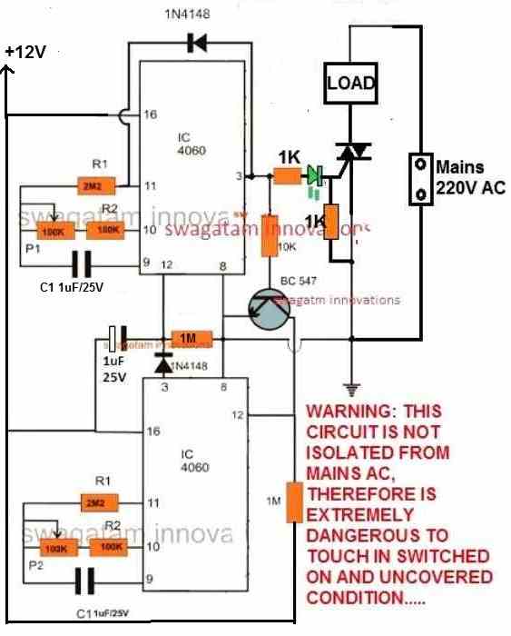 ” that you suggested, what would happen when connecting the 230 Vac mains supply , if I connected de L to the DC ground’s circuit and N (neutral) at the other end of the load?
I don’t know if it is implicit or not, in the article “Simple Triac Triggering Circuits Explained”, but I can’t find the answer to this question.
In Portugal and other European countries, it is not necessary to connect the L and N electrical conductors of the mains supply on the same side in the sockets, as the plug can be inverted.
Best wishes,
Hello João,
The Live/Neutral polarity is not critical in the specified triac circuit, you can connect the L/N any way round as you wish, it won’t have any affect on the working of the circuit.
But be very careful with this circuit, since the circuit is not isolated from mains AC it can be lethal to touch in part of the circuit in open and powered ON condition.
Hello Swagatam, thank you for your reply.
a) In the aforementioned circuit, is there any of the electronic components that need to dissipate more heat and therefore be greater than 1/4W or 1/8W, and the triac will need a heat sink?
b) To test the mentioned circuit with 12V DC, which components must be changed and what are their values?
Very soon I will share photos of the circuit that you helped me to build, using the email.
Best wishes,
Hi João,
Nothing will dissipate heat in the circuit, so no changes are required, all resistors can be 1/4 CFR. The triac BT136 may require a heatsink if the load is higher than 100 watts.
The circuit is intended to work with 12V, so nothing needs to be changed.
Sure, if you succeed with the project, please do send the pictures, I will add them to the above article.
Let me know if you face any issues.
Make sure to test the circuit without a triac and load, and only with LEDs, with one LED across pin#3 of each IC and ground. The LEDs must have a 1k series resistor.
Hello Swagatam, thank you for your reply.
What I intended to say by testing the circuit at 12vdc was the following: Assuming that the triac behaves like a switch in the ON state, if instead of using 230Vac, I use the same 12Vdc used to power the circuit, can I use as a load, for example a fan or an LED?
Best wishes,
Thank you João, the triac will latch once turned ON and will not turn off until power is switched OFF, so it won’t work with a 12V DC.
But you can use 12V AC from the transformer wires directly, that will work. Just replace the 230V AC with 12V AC, and the load can be an LED with series resistor.
Hello Swagatam, thank you for your reply.
Ok, I will use your suggestion, as it is much, much, much safer.
Best wishes,
No problem João,
please let me know how it goes.
Hello Swagatam, thank you for your reply.
Please clarify, what you are saying is that it is not possible to supply this circuit with a 9V transformer; 1.5VA , (about the meaning of 1.5VA, I will put the doubt about its meaning, in the category “https://www.homemade-circuits.com/how-to-make-transformers/”)?
Because it would imply new calculations of the electronic components used, and/or in this circuit reducing the supply voltage, would make the operation unstable?
It will be possible to use it, using a ZENER of 12V/1W (or less), also calculating its series resistance, instead of IC7812, the final voltage after rectification and filtering will rise above 9V, believe it will be sufficient/efficient ?
Best wishes,
Hello Joao,
The proposed programmable timer circuit using triac can work with any voltage between 5 V DC and 15 V DC. The ideal value is 12 V DC. If you use a 9V transformer with a full bridge rectification, that would produce around 9 x 1.41 = 12.69V or 13 V peak, which may be just sufficient for the circuit to work efficiently. Slight fluctuations in the DC will not affect the working of the circuit. However, for better accuracy you can include a 7812 IC. A zener diode will not work and could burn due to over current. Using a limiting resistor for the zener might reduce the gate current for the triac and might cause triggering issues for the triac. Nevertheless, you can try using a resistor with the zener diode and see if that works OK or not. The resistor value can be arbitrarily selected as 470 ohms. If you want to calculate it perfectly then you can refer to the following article:
How to Calculate Zener Diode Resistor
Hello again,
I forgot to ask which TRIAC do you think is suitable for this application (5W/240V=0.021A or 21mA), for ON/OFF rhythmic operation? There is so many part numbers…
Best wishes,
You can use BT136 triac, it is a very common 1 amp 300V triac and may be easily accessible for the local market.
Hello Swagatam, thank you for your reply.
Best wishes
You are welcome Joao!
Hello Swagatam, thank you for your reply.
Well then the IC 7812 will be. Do I need to apply a heatsink to it?
What will be the expected current consumption in the TRIAC version of your circuit?
If the current is more than (1.5VA/9V=0.17A or 170mA), then “Houston, we (I) have a problem”…
Best wishes,
Hello Joao,
The consumption will not be more than 20 mA, so 170 ma is more than enough for the circuit.
Heatsink will not be required for the 7812.
Hello Swagatam,
The 1st place I tried to find the IC 4060 data sheet was here in this knowledge sharing space, but without success (sorry if I didn’t see it).
The 2nd was on the net, but I found so many different designations, that I was confused. I found several letters before and after the reference 4060, which left me in doubt if it is the same IC. Can you explain to me how I should analyze these same datasheets?
Best wishes,
Hello Joao,
The prefix after the 4060 is not important. Meaning, you can use any 4060 IC that you can get. The number 4060 is the only important thing that needs to be considered on the IC. All 4060 ICs should work in the same way. So you can refer to any 4060 datasheet, the specifications will be all the same.
Hello Sir,
I would like to ask you if is it possible to replace the relay with a Triac and make the circuit without transformer? So it can be assembled inside small electrical outlet to control a mosquito destroyer (240V AC/5W).
Thank you in advance
Hello Joao,
You can try the following modification:
Dear Swagatam,
Thank you for your fast reply. I´m going to try it, as soon as possible.
Please clarify me, the green LED is going to light up, at the same time as the TRIAC switch ON, or will it work as a standby indication, turning OFF when the TRIAC turns ON?
Do you believe it is not necessary to stepping down and rectify the AC mains, before de Zener? If so, is it sufficient 1W or do I need more?
Best wishes
You are welcome Joao,
The green LED will light up when the triac switches ON, and will remain switched OFF as long as the triac remains switched OFF.
The AC mains will be stepped down to 12v due to the presence of the 0.33uF/400V and the 12V zener diode, so no need of any additional circuit. Since the 0.33uF will be able to generate only 25 ma current, a 1 watt zener should be quite sufficient according to me.
Hello again,
So just because it’s only 25 mA, you don’t need a resistor in parallel with a 0.33uF capacitor either.
Best wishes
You can put a resistor parallel to the 0.33uF/400V capacitor to ensure that the capacitor is quickly discharged whenever the circuit is unplugged from mains AC. This maybe helpful to avoid a possible electric shock from capacitor discharge. However, this resistor has nothing to do with the working of the circuit.
Hello Swagatam, thank you for your reply.
Can you teach me how to calculate this resistance, in a simple way? I read (I don’t know where) that it can also serve as a fuse, is that true?
Thant you in advance.
P.S. Please tell me where I can ask my questions about LED power supplies.
Hello Joao,
I do not have the formula for calculating the resistor parallel to the 0.33uF capacitor. However, it is not required anyways, because any resistor between 330K and 1M should be able to discharge the capacitor in less than a second, so calculating may not be crucial.
No, it will not work like a fuse since it is not positioned to work like a fuse.
For LED power supply you can ask under the following article:
https://www.homemade-circuits.com/how-to-design-simple-led-driver-circuits/
Hello Swagatam, thank you for your reply.
Best wishes.
My pleasure Joao!
Would the circuit above need to have P1, R1, R2 and C1 changed in order to have the timers do minutes, instead of hours?
Only P1 and C1 needs to be changed in order to change the output delay. Alternatively only one of these could be changed for the same.
hi dear sir
i need a timer circuit that start a pump on via relay for 2 hours to circulate water of pool then off for 22 hours and again on the pump for 2 hours .repeat daily.
thanks a lot
Hi Abbasali,
2 hour ON and 24 hour OFf can be difficult to adjust, instead the timing can be adjusted to 144 minutes ON and 1296 minutes OFF.
como se instala una tarjeta que usa un CI MC14541BCP DE HORNO TOSTADOR TOASTMASTER MODELO 357S SI PUEDE INVIAR DIAGRAMA
Sorry, I do not have the information with me regarding How to install a card that uses an IC MC14541BCP OF TOASTMASTER TOAST OVEN MODEL 357S
Dear Sir,
Need circuit design for solenoid valve working. the case is that I have 2 switches, once I push on left switch it should on the left one solenoid valve and when I switch on right one the right one solenoid should work. once both switches are on then left solenoid valve should work. can you give me pcb circuit design for that. It will be great help for my project.
Thanks
Arun
Dear Arun, What is the specification of the switch? Is it SPST switch or push button type?
Dear Sir,
In addition I measured voltage between PIN3 and PIN8 shows 0V. Between PIN3 and GROUND of circuit shows 5V on both ICs. Relay is not activated and both LEDs are glowing for ewer.
Dear Sir,
Thank you very much. It works perfectly.
Nedzad Niksic
Thanks Nedzad, glad it is working now!
Dear Sir,
I copied your PCB layout and assembled the circuit exactly as it shows on PCB layout components drawing. All capacitors are 1 microF. For C3 I used tantalum. When power ON the relay is activated immediately and both LEDs are ON for ewer. When I change transistors PINOUT (here in Bosnia, you newer know who is manufacturer of such small transistors, so the PINOUT is problematic) the relay is not activated, but both LEDs are ON for ewer. Please HELP. I need the circuit that activate the relay twice a day for 2 minutes to water my plant.
Hello Nedzad, please do not rely on the PCB design since it was designed by an external source, and it might have problems.
Please build the circuit on a veroboard first according to the given schematic, and confirm its working, and then get the PCB designed from a professional designer.
The circuit is thoroughly tested and will work without any issues.
I have made this and it delays the switch-on of load first time you switch it on. The lower timer seems unable to reset the upper and they both freez counting and remain idle until you manually reset the upper timer. What could be the problem?
That should not happen. I have checked this timer thoroughly and it worked perfectly for me. Even in the video you can see the timers are changing over perfectly and providing the necessary delay outputs.
You can try checking the lower 4060 timer separately, and check whether it is working properly or not.
Thanks for the advice, retraced my circuit and found I had not properly configured the resetting/latching section of the two 4060. Works perfectly now and I am using it to turn on borehole pump for a set short period after waiting for longer period.
Thank you for the update, Glad it is working now!
Load shedding problem,
If you turn it on again, it is being reset, is there any solution? I want it to start from the time it stopped.
Sorry, that may not be possible with this circuit.
Hi
if i want make a timer that 8 sec on, 1 sec off, 1 sec on, 1.5 sec off, then repeat ; can i use this circuit ?
The above circuit is a 2 stage timer, it cannot be used for 3 stage timer as you have mentioned. For your requirement a 3nos IC 555 sequential timer would be required
Greets Swagatam,
The circuit you have here looks perfect for a 6 hour on/18 hour off timer I wish to apply to some LED-based artificial Christmas trees I use in front of my house. Looking at the circuit and PCB layout, there seems to be some discrepancy concerning the 1M resistor. Is it truly connected across pins 8 and 12 of the upper 4060 and across pins 3 and 8 of the lower 4060? When confirming the schematic with the PCB layout, it looks as if that 1M resistor has nothing to do with those 4 mentioned pins. Also, I will assume that the 2 monitoring LEDs, D4 and D5, on the PCB layout are still in the old locations you mentioned in your description’s update? Thank you for your reply.
Hello Kevin, please do not depend on the PCB layout as it was created by a non-professional individual. The diagrams are correct, and you can design your own PCB with a little effort.
So that 1M resistor IS supposed to be between all four of those pins? That puts a new spin on the circuit. And darn, already did some circuit drawing based on that PCB layout – oh well, need to sharpen my pencils again 8). Also noticing that the red LED has a 10k resistor on it – should that be a 1K resistor? Or does it matter, since the green LED is also reliant on a 10K resistor? Believe me when I say that I will breadboard this circuit to confirm its operation in either instance. Thank you for your reply, then and now.
The 1M is actually between pin#12 of the upper 4060 IC and the ground line. The pin#8 of both the ICs are Vss pins or the ground pins.
The modern RED LEDs are extremely bright!, using a 1k resistor may cause it to produce blinding illumination, that is why I have used a 10k for the RED.
The 10k for the green is a must because the 10k is actually for the transistor base, which is should be actually 22k, but normally I use 10k for a relay with a coil resistance of around 400 ohm. So the green LED might look a bit dim, nevertheless if you find it too dim, you can try lowering the base resistor to 4k7. I actually liked bread-boarding as they are not 100% reliable, I would rather suggest to go for a strip-board and assemble by soldering the parts for reliable operations.
Ok, I see that pin#12 is not only tied to the 1M in the schematic but also to the 1N4148 that goes to pin#3 on the lower 4060 IC and the polarized capacitor that is also connected to pin#16 of the lower 4060 IC. This is all on the left end of the 1M. The right end of the 1M is as you say, sharing a ground connection with the two pin#8.
I have some older LEDs that will probably work in this circuit just fine and not be killer bright; I was thinking of just having one end of the LED in the circuit and the other end with its dedicated resistor and continuing to source voltage. After all, the LED is only ‘monitoring’ the signal and not actually a functioning part of the circuit. What say you to this thought?
Finally, what relay would you use for this circuit? I’m looking at an uxcell JQC-22F-12VDC-S-Z DC 12V Coil, but when you mention the resistance of the coil itself, that info I do not see yet; will look for that.
Oh, 1 more item – since you say you are using the 10k for the red LED to be more visually comfortable, are you also saying that the 10K has nothing to do with the BC 547 across the collector and emitter? If that is so, that may eliminate a little headache I’m experiencing in my circuit design. Thank you as always for your time and reply.
Yes all the shown connections in the schematic diagram are accurate and correct.
You can connect the LED to any other favorable position, it will be fine as long as it fulfills the requirement.
The relay will depend on the load current, for loads below 5 amps, any ordinary 400 ohm coil resistance can be used.
The resistor across collector/emitter of the BC547 will not matter as long as it is over 1k ohm.
dear swagatar, to which pins the ic counter leds in the video will be connected
You can try connecting an LED with pin#14 or pin#15 for both the ICs, with respect to the ground line….make sure to have a 1k resistor in series with the individual LEDs
thank you so much sir..
You are welcome ismail!
Dear Sir:
I am looking for a controller which will put the load for 10 seconds and cut off 1o minutes. It should go cyclic manner.
I would like to have a PCB also for the same.
Would you please help me? My load is operating in 12V.
With regards
John T. Eapen
Hello John, since the ON/OFF periods are equal and short, you can implement it using any standard oscillator such as
a transistor astable
NAND astable,
4047 oscillator
555 astable
4060 astable
Hi Sir ,
I want circuit diagram for LEDs which will turn ON from 4am to 6am and 7pm to 10pm.automatically and daily at same time
Hi Prakash,
You can modify the first circuit presented in the following article:
https://www.homemade-circuits.com/how-to-make-long-duration-timer-circuit/
There are 10 outputs from the IC 4017, you wil have configure these outputs accordingly to get the required results.
Thanks for reply… you are doing great job.
You are welcome, please keep up the good work!
Sir please tell me what is the green and red symbols in circuit?
Asad, those are RED and Green LEDs, if you cannot understand the components then how did you buy them?
Sir i buy them on my own thinking…
OK, all the details are given in the diagram, please compare your components with them and assemble.
Very thankyou sir… I am assembling this circuit for egg incubator turner. Is it will work 24 hours?
You are welcome Asad, yes you can use it for 24 hours or continuously forever.
Sir please tell me what is c106 scr That is connected with button i cannot buy this because not found on shops & tell me that the button is necessary for switch on circuit & this button is push button or another type of button…
C106 is an SCR, the button is a push button. It is required only if you wish to have a push button, otherwise it is not required, you can use the first circuit
Hi! Sir Please Sir Please Answer to My All Questions.
#1): What are the green and red symbols in diagram like led diode?
#2): Is All Diodes that are used in circuit are 1N4007?
#3): What is the Wattage of Resistors that are used?
#4): What is mean of arrow on P1 & P2?
#5): What is C106 scr with switch?
#6):For What thing the switch is used?
#7): The upper +12 of switch is will connect to the +12v of circuit?
#8): Where We Connect Leds Like your video?
*Can You Give Me your Fb Link or something like this for Contacting*…
Hi Asad, You should try to figure them out yourself because all the answers are provided in the diagram itself and article description. It seems you are extremely new to electronics in that case you must first learn all the basics of electronics and only then attempt this circuit.
Sir please give me Answer… I want yo apply on my egg incubator please sir please… 1 Already Purchased All Components….
Asad, those are RED and Green LEDs, if you cannot understand the components then how did you buy them?
nice desings
Hi
nice website. very useful information. Unfortunately I have built another circuit with 4060 but its not working as it said. can I send the circuit for you? maybe you can help me with that. i really appreciate that.
Hi, you can upload to any free image hosting site and provide the link to me here, if possible I’ll try to solve it for you…
Hi and thank you for sharing your great circuits. Is the pcb layout for the 1st timer, inverted & sized correctly or do we still need to invert & check sizing?
Hi thanks, the PCB was designed and submitted by an external source, so the users are advised to check and verify the design by themselves and then implement it.
Sir Please Tell Me What Is 2M2 and 1M in the Circuit… & please tell me which is the latest diagram that i will use to make this… Please….
Asad, you can build the first diagram. 2M2 = 2.2 Mega ohm, 1 M = 1 Mega ohm
Hi again. I built the circuit & it is working very nicely. I’m just struggling to calculate the timing resistors. Currently I’m not able to set the time’s to low value’s like 2secs (just for testing) as stated. I end up waiting hours to get the green led to turn on, no matter how I adjust the pots. Can you please explain in a bit more detail, how to calculate the timing resistor values. “Sample Delay / Desired Delay = Selected Resistor / Unknown Resistor”. What value do I put for the “delay”? Is the value in seconds? Eg: 1hr = 3600. Also I’m uncertain about “Connect any arbitrarily selected resistor above 100K in place of P2/R2 in the upper circuit.” Are you referring to the P2 (potentiometer) connected to the lower IC4060 & R2 (fixed resistor) of the upper IC4060 and should they both be the same value? I appreciate your assistance. Thanks so much.
Hi, yes P1, P2 are the potentiometers or the presets in series with the resistor R2. You can replace this combination with a single fixed resistor
I have updated the calculations with a practical example but this example does not exhibit the real results, it is only for understanding purpose..
Thanks for your reply.
I’ll be sure to double check it then.
Thanks so much.
Hi
I require a mains monitoring circuit which switches a 230 volt ac supply off and switches an inverter on if I have a power cut and then returns the 230 volt ac supply into the circuit when the mains then returns stable for minimum 60 seconds. The inverter is powered by a 150 amp/hour leisure battery which is recharged from the 230 volt ac supply. There is a stipulation wherein the inverter output can only replace the 230 volt ac supply when it itself is stable (after 5 seconds). So, in effect, I would have an uninteruptable power supply which, in state 1, would switch through a 230 volt 16 amp ac supply but when this fails, state 2 would be initiated which is a 4000 watt inverter, which is fed from 12 volts dc and would be switched into the circuit after 5 seconds and when the 230 volt ac supply returns for at least 60 seconds, state 1 would be re-constituted. I already have the inverter and the battery and charger,
I think that I have (with some difficulty) explained my situation. If you can help me with this logical conundrum, please do.
Thanks and regards
Ivor H. Barnett
Logical Diagram:
230 volts ac present >> 230 volt ac switched through to load. >> Inverter output isolated.
230 volts ac absent >> 230 volt line isolated. Inverter powered on (single pole 1 way relay contact) >> 5 second delay >> Inverter output switched to load.
230 volts ac line returns stable for minimum 60 seconds >> 230 volts ac switched to load. >> Inverter output isolated.
230 volts ac absent—— Inverter output absent >> Load isolated from both supply lines.
Hi
It would seem that your Mains High Low Voltage Protection Circuit with Delay Monitor would fill mt necessity perfectly. Do you have a PCB design for it or must I make one myself?
If you can help me with this, please reply to me with the price.
Thanks and regards
Ivor Barnett
Sorry, I do not have a PCB design for it, you will have to contact professional designer for this. But you must first test the circuit on a general PCB before designing the PCB.
Hi,
I have a sprinkler coupled with solenoid valve and I want to automatically switch it ON every evening @ 5 pm to 5:30 pm (only 30 mnts a day) and rest of the time it should be in Off state. So please can you set a ckt. Diagram for the same.
Hi, you can use the first circuit from the above article. For C1 use 20uF/25V for the upper 4060 circuit, and for the lower 4060 circuit you can use a 1uF/25V capacitor. The 25uF capacitor should be configured using 20nos of 1uF/100V PPC capacitors in parallel. For calibrating try any resistor such as 47k resistor in place of P1 + R2, and check after how much time the pin#3 goes high. Use this value in the following equation to get the actual resistor for the required time :
47 / R = delay obtained for 47k / required delay
R is the resistor which must be used for the P1 + R2 or P2 + R2.
Ok sir
Hello Sir,
If zener diode connecting IC-2, 3rd terminal to IC-1, 12th terminal went wrong then such thing happens? Because yesterday there is accidental short occurd in 3rd terminal to 12th terminal.
Mostly it will have no effect, but make sure the short is removed now.
In my ckt. Referring to fig: 1, when the 1st IC O/P gose high, 2nd IC suddenly resets the 1St IC, so O/P remains ON for a fraction of second and turns off. O/P LED only blinks. Initially the ckt. Worked properly, but the problem occurred after 5 days.
Please check or replace the P2/C1 pats values or settings of the lower 4060 IC, and check the response again.
Thank you Sir..
Hello Sir,
So the value of R for upper IC is kept large and lower IC is kept verry small.
Yes that’s correct.
You can checkout the following circuit
Many thanks and a good new year tto you.
Regards
Ivor
Thank you, and wish you too a Happy New Year!
Hi, it looks feasible, I’ll try to figure it out and design it soon….
Hi…
I want to develop Circuit for my one of Commercial Product,
Request you to contact me as soon as possible,
Please email me back.
Thanks…
Hi, I have replied to your email.
Hello sir
I’m required to create a logic circuit project that is programable meaning it must have a code to it
I decided to create a switch timer for homes but I’m not really sure about the components to use and how to design them in my project
How can I go about it with designing my project
Hello Charmaine, please provide more details regarding the functioning of the project and the type of code you want it to work with?I’ll try to figure it out..
Hello Sir..
I want make timer delay 90minutes use CD4060 to control LED.
idea use single push on /off button to turn on/off LED, also LED can turn off automatically after 90 minutes.
1. When push button… LED turn ON, Timer start counting.
2. When push button once again … LED turn OFF, Timer stop.
3. When push button once again.. LED turn ON and Timer start counting.
4. if Timer reach 90minutes, LED turn OFF.
5. if push button once again LED turn ON and Timer start counting
Can you teach me which circuit suitable with my idea ?
I try use Timer CD4060, but I cannot stop Timer without waiting until timer reach desired time.
Hello Damanhuri,
you will have to use an SPDT switch for this, a push button will not be appropriate.
Connect pin#12 of 4060 with the center terminal of the SPDT, connect one outer terminal of the switch with the positive line, and the other with the negative line.
That’s all, your application will be fulfilled with this!
Toggling the switch up/down will accomplish the required operations!
Hello Sir..
Thank You for your advice.
i try, But I found problem. when select switch SPDT to (+) or (-) … only timer stop or start counting, but output IC no change (same as previous condition).
– SPDT to (+) –> timer stop, Output Low.
– SPDT to (-) –> timer start counting, Output still Low. (Output High if timer reach desired time).
– after Output High,
I need every select switch SPDT, Output also changing.
Hello Damanhuri, The IC 4060 will always begin counting with a zero logic, to invert this you can connect a PNP transistor with the IC output. Connect its base with the IC output through a resistor 10K. Connect its emitter with the positive line, and then the relay can be connected across the collector and ground.
Hello.
Thank You for your help.
I mean, when Output IC Low, and toggling the switch, Output keep Low.
I need Output change every time toggling the switch.
For Example :
a. ON/OFF mode during timer counting (not yet finish desired time).
– Push switch –> Output Low –> Push Switch –> Output High –> and so on.
b. ON/OFF mode with Timer reach desired time.
– Push switch –> Output Low (timer count) –> Timer finish –> automatic Output High –> Push switch –> Output Low (timer count) –> push switch –> Output High –> push switch –> and so on.
Sorry for your inconvenience cause.
Thank You for your guidance and your patience sir.
I study some option :
1. I use single push on/off button on pin#12 (as reset). and adjust Capacitor on pin#9 to change clock to faster counting. (For example use 2 parallel Cap 100pF and 10uF).
when push button –> timer counting –> push button –> i remove Cap 10uF to faster timer and then timer become finish –> output High.
But I don’t know how to use electronic switching circuit to control this Cap.
2. I add Push ON/OFF latch transistor circuit to cut off Vcc of IC 4060.
so, when push button –> Vcc ON to IC 4060 –> timer start counting –> push button –> Vcc cut off to IC 4060.
but problem, when push button –> Vcc ON –> timer start counting –> timer finished –> push button –> Vcc cut off to IC 4060 (suppose Vcc ON).
Hi Damanhuri, for electronic selection you will have to use a relay and a flip flop circuit, that will solve the 1) problem, as shown here:
https://www.homemade-circuits.com/simple-touch-sensor-switch-circuit/
for the second option you will have to operate pin#12 with a SPDT switch as described earlier, Vcc ON/OFF will not work.
I can implement the a) operation, it will be on the output side of the IC. meaning while the timer is counting the output state can be reversed as required from high to low or low to high, so that when the timer finishes counting it will again revert the selected logic by the user.
I am sure not about the b) option
…and make sure to connect the output pin (pin#3 recommended) with pin#11 through a 1N4148
Sir the switch is ok and working properly,thankyou for your guidance and patience sir,????????????,..my only problem now is how to set my desired time,.do you have a tip sir how to get your desired time needed?,.thankyou verymuvh,.????????????
That’s good Ken, I have updated the method in the article. Please check it out
Hi sir, I am learning a lot from you, i am burning with desire to try your circuits
Sure Gerald, I wish you all the best!!
Thanks,…sir it is possible to put a reset switch in lower ic?,.how can i do that sir?,.that when i push the reset switch the lower ic reset and start counting,.and the upper ic stop counting,…
Connect a 1K in series with the pin#4 of IC 555 in addition to the 1n4148
Now shorting pin#4 with ground will reset the IC
Can u send me a schematic sir,..the lower ic is 4060 sir,..i need a reset switch sir that can stop the upper ic counting and the lower ic start counting,.thanks
So i can not run the lower ic that can bypass the upper ic,…ok sir thanks for assistance,,.????
It’s probably not possible, because the upper IC won’t stop counting until its pin#3 goes high.
Yes sir i made the reset in upper ic…how about in the lower ic sir?,.because i connect the collector of bc547 in the pin12 of the lower ic with 10k,and i short the 1M in pin12 of lower ic to reset the lower ic like you said,..it reset the lower ic sir but it only works if the lower ic start counting sir,..i what a switch sir that even the upper ic is not yet finish counting,when u press the switch the upper ic stop from counting and the lower ic start to count,.pls help sir
Ken, This is a 2 stage programmable timer which is designed to work in sequence. They cannot run separately. Otherwise you may have to create two of these without linking them together through the lower BC547
I need to add a ic 555 sir?,..but the lower ic is 4060,how can i rest it to stop the upper ic counting and the lower ic start counting..
When i short the 1M in pin12 of the lower ic, the upper ic is still counting,.. I want a switch the stop the upper ic from counting and start the lower ic from counting,..
Sir how can i put a switch that can stop the upper ic automaticaly from counting and make the lower ic start to count,.,.like bypassing the upper ic to switch the lower ic 4060,…for example i want to use the the load in my circuit,.when i press the switch the lower ic will start to count,.by passing the upper ic causing it to stop from counting..
Ken, connect a push-to-ON switch across the 1uF connected with pin#12. Pressing this switch momentarily will reset the upper IC
OK, I think I got confused with the other comment sent by Mr. Davis.
If you have IC 4060 for the lower side you can do in this way:
connect pin#12 with the BC547 collector though a 10K resistor. Now shorting the 1M at pin#12 will reset the lower IC
Whats the main use of c106 scr in the circuit sir?,..when you push it on using momentary switch it stay on until the power failure occurs or you remove the supply?
it’s for latching power to the circuit with a single push of the button…the latch is restored back to OFF when power is switched OFF
Ok sir,..why when i push the button it stay on when i release, it turns off,.what should be the problem of the circuit sir?
OK, it’s probably due to the 1M resistor, please reduce it to 10K and check again
I try to change 1M to 10k sir,.but the result is the same,.when i release the button the circuit also stop,..
try it separately. Connect a LED with 1K across anode and positive line, and cathode to ground. If the led latches ON then the ScR is good otherwise there could be some problem with the SCR or its connections.
Hi SWAGATAM I made the circuit for 555 timer and tested it worked for short delay I wanted but when I connected it to the upper 4060 circuit as u told me . It has failed to trigger the load , testing both circuit separately work but don’t know why it has failed .help.thanks
Hi Davis, it has to work, try connecting pin#4 of IC 555 through a diode 1N4148. Cathode will go to pin#4, and anode to pin#3 of 4060. Also connect a 10K from pin#4 to ground. To monitor the output of IC555, connect an LED from its pin#3 to ground via a 1K resistor.
Thanks my master SWAGATAM it has worked perfectly.
I am glad it worked!!
Hi SWAGATAM, for upper circuit help me how to replace the lower 4060 ic with 555timer circuit for short time count ,the reason I have hcf4060 ic tested and was counting as I tested first stage but when replaced with cd4060 the ic failed to count I bought many from different store failed to work but for hcf4060 worked perfectly for that reason I want lower stage I use 555timer for short delay and upper stage using my hcf4060 for long delay.help me my master thanks
Hi Davis, you can probably do it in this way:
remove the lower BC547, and its base 10K
configure IC555 in its basic astable mode. Connect its pin#4 with pin#3 of IC 4060
Connect pin#3 of IC555 with pin#12 of IC 4060 through a 1N4148 diode.
This should do the job
Please how can the last circuit be made to run continuously 24/7
Sir what replacement for c106scr can i use?.thnks
Ken, you can use any small SCR between 200mA and 1 Amp, such as this:
https://www.mouser.in/datasheet/2/389/x006-957645.pdf
Sir can i change d 12v relay to 9v relay?,..and i can use 9v 250mA as a supply voltage?,.thanks sir
yes you can do that, no problems.
What do you mean in unnecessarily costly sir?..yes sir thats the switch i used,..the momentary switch sir,.what happen sir in the circuit when i push it?,it turns on right,.and when i release the timer will stay on until the power failure occure to stop the circuit?
I mistakenly read it as BT139.
BT169 is perfectly fine and a cheaper option than C106.
Sir can i use bt169 in replacement of c106 scr? What push switch will be use sir,?the normally close switch that when you push it turns On then when you release it turn to normally close again,.or the switch that when you push its on and when you release it stay on,.pls help sir thanks
yes you can use it but it will be unnecessarily costly. The switch is push-to-ON type meaning it will be ON only as long as pressed and will be OFF when released.
what ampere of the transformer can i use sir?,.or the ampere rating does not matter,.what ever ampere i use?,,,..sorry for asking to many question sir,..thanks
Ken, It should not be lower than the minimum requirement of the circuit and the load….while higher amps will not have any effect since the circuit will draw only the required amount of current, so no problems.
But i can use also a 12v 250ma transformer right?-.thanks for ur help sir
you can use 12v if the relay is also 12V, otherwise not!
Sir can i use 2n2222 or bc547 for replacement of c106,.thanks sir,..
Ken, the SCR is used because it is able to latch when the push button is pressed, if you want to replace it with BJTs then you will have to configure 2 BJTs as shown in the first diagram from this article:
https://www.homemade-circuits.com/2015/07/how-thyristors-scr-work-tutorial.html
It is designed to run continuously
In reference to washing machine agitator circuit because there is no comment section, can I use 12v relay. Can I use electrolytic capacitor of 10uf/25v polarised because there is difficulty in getting for C2 etc. Thanks
Please how can I make 3months timer
Please give a guide, I didn’t get how to do it. I have gone through some of your articles on ic4017.
In the present diagram the delay generated at pin#3 if IC 4060 is increased 10 folds by IC 4017 at its pin#11, if we add one more IC 4017 by connecting its pin#14 to pin#11 of the first 4017 then the pin#11 of this second 4017 will give 10 times more delay than the first IC4017…in this way if go on adding the 4017 ICs, the subsequent pin#11 of the ICs will enable 10 times more delay than the preceding 4017.
I hope you understood now.
You can try the following design:
https://www.homemade-circuits.com/how-to-make-long-duration-timer-circuit/
Just go on adding more number of IC2 4017 in sequence to increase the delay by 10X for each addition
comment was accidentally disabled, I have enabled it now.
Yes you can use polarized capacitors for all the shown capacitors.
Hai sir…*
Few doubts sir…
1.Pls tell the function of 1uf polarised capacitor in between 3 and 16..
2.when the upper case counting starts.The lower case ic not started counting what’s the reason..
When the upper case ic reaches the time counting then automatically lower case ic starts count and resetting the whole ic…
Pls explain it how this happening…
Kesav, the 1uF is connected with pin#9, it is the timing capacitor and this capacitor along with the resistors at pin#10 determines the delays or the frequency rates at the outputs of the IC. The capacitor must be non polarized ideally
the upper and the lower timers are designed to work sequentially or in a cyclic manner, that’s why you see them work one after the other and not together,
Thank u sir…*
Sir ,
Love to see your respnoce, you are in realtime.
I thought PCB design is through a software like eagle is easy. I can try but I don’t have PC or laptop :-‘)
Thanks Anjali, I love answering questions, and I am online most of the time here. I too do not have any PCB software because my expertise is in the field of designing circuits and not PCBs. I only have Coreldraw which is a great software but not a specialist for PCB designing.
If you are into some kind of electronic business then you must have a PC with you.
No I am not belong to electronic field. Well coral draw is very good software but it cannot produce circuit digram to PCB layout.
But sir you are the admin of this very good blog you must have something like eagle
I am sorry I do not have or use any special software such as Eagle, I totally depend on Coreldraw and do everything with it right from schematics to PCB
Sir this pcb layout have both side. may affect on etching ?? I need separate sir four led is not used in circuit digram ??
Hi Anjali, I am sorry I am not good at designing PCBs so it’ll difficult for me to modify the design for you. All the PCBs were designed and acquired from an external source. For the flashing LEDs, you just have to add an LEd from pin#14 of the two ICs to ground. just make sure the LEDs have a 1K series resistor with them.
Kudos for the great projects sir! I am Israel you have really inspired me through your home made circuits blog. i am a student and i would like to build an incubator circuit that checks humidity say at 22, temp at 38 celcius, and automatically forwards and reverses a 12v motor
thanks my email is musomaji@gmail.com
Thank you Israel, I have one similar Arduino based circuit, which you can find here
https://www.homemade-circuits.com/incubator-using-arduino-with-automatic-temperature-and-humidity-control/
Sir i want to use this circut to control water heater but it start automaticly with power on i need a programable timing circuit that start count with push button and dont start after power cut.
Hi Suleman, in this circuit the relay will not start on power switch ON. he relay will switch ON only after the upper IC has finished counting and the upper IC’s stipulated time has elapsed.
There may be some fault in your circuit or it could be due to the low capacitor value at pin#12 of the upper IC, I have changed it to 1uF…please use this new value and check again
I made this circuit several times again and again but i think there is something wrong in the diagram because both two ic work Properly if i don’t connect the lower ic pin 3 to upper ic pin 12 with 1N4148
If i connect it damage the ic
The circuit is thoroughly tested by me and there’s nothing wrong that I can see in the above drawn diagram
Pin#3 from the lower IC applies a positive logic to pin#12 of the upper IC so that the whole system can reset back to the original condition, how can there be anything wrong in this process??
you can try this manually also, just touch the pin#12 of the upper IC to the positive supply with a wire, and the IC will reset back to zero.
make sure your supply input is not above 12V ideally, because 15V is the maximum recommended level.
If your IC is getting damaged when pin#12 is touched to (+) supply then your IC is definitely faulty or duplicate in quality.
is it possible to use one 4060 and one 555 IC please give me diagram
I need a circuit that on for 10 min in an hour Please help…….
10 mintues is OK for IC 555, i’ll try to update it soon.
it is possible, but IC 555 will give inaccurate delay results and will be suitable only for short delays.
For the push button the circuit will need some modifications…I’ll try to update the new design soon…
dear sir i want 3 hour timer circuit when power is on the timer wants tostart counting after 3 hours the output relay comes to activate after that i will reset the circuit after resetting the circuit the counting will repeat the same proces
dear kanagraj, you can try the following concept
https://www.homemade-circuits.com/how-to-make-simple-versatile-timer/
Hello Swagatam. I am your new subscriber. I already made some of your circuit design. And i want to say you thanks.
Thank you and welcome to my site Ani, I am so glad to have you on board
Sir,
I would like to refer to a post for which you have replied as follows.
************************************************************************
edwin siy says
December 3, 2015 at 8:48 am
Good day Sir,I build this awesome circuit but the problem started when I switch on the red led and relay instantly activated while the green led light up after 5 sec. and goes off after 5 sec. but the red led and relay still energize. The green led goes on/off 5 sec. interval continuously with both red led and relay energized. The only components I change are the ff. P1 to 2m and R2 of the lower circuit to 10k and pin#9 of the lower circuit to 0.1uf ceramic cap,the rest stay as is. I know by the way I explained,you already pictured what went wrong. Thank you
Reply
Swagatam says
December 3, 2015 at 2:42 pm
Good day Edwin,
red LED will light up when the circuit is initialized, this is correct, but this should not activate the relay because the BC547 is not supposed to activate when the red LEd is ON…it looks contradicting.
when green LED lights up, the red LEd should shut off….so again the result is incorrect in your circuit.
try increasing the setting of the pot and check the response in a slow motion to read the operations correctly….there could not one but more issues in your circuit which will need to be traced and eliminated…
Reply
*****************************************************************
Sir, this is the same problem I came across. I also changed the C1 & C2 to 0.22uF and P1 & P2 to 500K since I needed 10 minutes ON and 20 minutes OFF sequence.
As mentioned in Mr. Edwin Siy’s post, the relay and the red LED keep on activated all the time while the green light comes on and goes off to the set time interval. Further I notice, once the green LED is ON the brightness of the red LED decreases.
Sir could you please give me an advice and help me to solve this problem.
Thank you.
Regards.
Fernando
Hi Fernanado, please understand yourself and try to figure this out….if the red LED is ON, that means pin#3 has to be at zero logic.
If pin#3 is at zero logic how can the BC547 conduct? because the BC547 will require at least 1V to switch ON.
My guess is that your IC is not of good quality and due to which it might be leaking some voltage while the upper IC is in the counting mode….
you can probably remedy this by adding a diode in series with the emitters of both the BC547 transistors….anode will connect with the emitter, while the cathode to ground…do this and check the response.
also increase the value of the 0.1uF cap at pin#12 of the upper IC to 0.33uF or 0.47uF so that the IC gets correctly reset when the power is first switched ON.
Sir,
Thanks a lot for your prompt reply and for your kindness. I shall try your advice.
Thank you.
Regards.
Fernando
You are welcome Fernando!
Hi sir
Myself Rishabh, sir I made this circuit but the problem is that the green led along with the relay turns on when I disturb the wire connected between voltage source and the circuit or when I shake the circuit board , this is a weird please help me.
Hi Rishabh, there could be some kind of loose connection in your circuit, i hope you have made it by soldering and not on a breadboard…please check the solder connections and resolder the joints if possible…
Hi sir the circuit is not working properly only the red led is glowing when the p1 is in lowest value , please help.
Rishabh, Please go through all the comments and try to solve the problem by referring to them…I cannot troubleshoot your circuit fault because do not know what mistake you might have made in it…it will need a practical checking….
Or you can first make two individual 4060 timers separately and check them, if you succeed with them, then you could combine them as per the given figure for the final result…
Hi sir,
My name is Rishabh and I want to ask you one thing that can i use polar caps in this circuit because unfortunately I have got all polar caps of desired rating.
Hi Rishabh,
yes you can use them for all except the ones which are connected at pin#9 of the ICs….here you can put two polar capacitors in series to make non-polar capacitors as shown below:
—–+||——||+——
or
—–||+——+||——
Hi Sir could you help me design a circuit that outputs 3v or 5v for 60 sec every 12 hours? thanks in advance
Hi John, the above shown design can be used for your application, the upper IC could be set for achieving 12 hour delay and the lower IC for 60 seconds
First of all I would like toltell you that green led is glowing (very low) at the ssametime when red LED is on.
I removed the diode. Checked there is no blinking only continuous glowing . Also both the LED is glowing . Within 3 minutes upper ic temperature got too high . Extremely hot.
Plz help… can you plz share another circuit for this. I want to run the motor (cooler) for 3 minutes and after 3 minutes it should be off for 20 minutes. And so on….
That's great, it means you have almost succeeded with this project.
your relay is definitely not working because of the inadequate input supply, please replace it with any 12V/1amp AC/DC adapter, and it will instantly start responding
I again tried. Both ic are are working well. Both led are indicating according to their time. How ever relay is not triggering.
I used an old battery for power supply whose voltage is 9 voltage.
Is 12 v supply is must?
Can I use a DC power adapter of 12 V output & what should be the current out put.
Plz suggest.
Ok sir.thank you.
Meanwhile I will do it from a fresh start. Thank s for ur support
If possible I may update another circuit using IC 4017/IC555.
by the way the above IC4060 circuit has been thoroughly tested by me…
this IC can become hot under any of the following 3 conditions:
1) output short circuited
2) supply voltage above 16V
3) IC itself is duplicate and faulty.
I cannot troubleshoot your circuit because I cannot see it practically.
I would suggest you to buy another good quality IC, and first build a basic timer circuit as explained in the following article.
https://www.homemade-circuits.com/2011/12/how-to-understand-ic-4060-pin-outs.html
connect LEd across its pin#14 and check whether it blinks or not….confirm this and then you can go ahead with the above programmable design as before
I have done the following things.
1. In Pot 1 & Pot2 : I used two pin. i.e. center pin & side pin.
Following connections done individually for both the IC.
2. 2.2Mega Ohm connected between ic pin no. 11 and centre pin of pot.
3. 100k resistance between IC pin No. 10 & side pin of pot.
4. 1uf/230vAC between IC pin no. 9 & center pin of POt .
3. All other component as per circuit.
Now what happening is :
1. Red LED is glowing /on and relay is operated.
2. Red LED is always in on condition. (Green LEd in not glowing).
Diagnosis result:
Upper ic: I connected a led +500 ohm resistance between IC pin no#15 and Vss. LEd not glowing. But when connected between pin no. #7 & Vss then continuously glowin.
Lower ic: led not glowing (gor pin no.# 15 ot pin no. 7)
I also tried to put bkth the pot on 0 ohmm. Still red LED is always on. There no any delay at all.
Plz suggest what to do.
rememeber when red will be off and green will be ON when power is switch ON, red will light up, and green will shut off when the upper IC has finished counting…and this will mean that the lower IC has begun counting.
as soon as the lower IC finishes its counting it will erst the upper IC which will start counting again…the cycle will continue…
It looks like your upper IC is getting latched on power switch ON, but in that case the lower IC should begin counting.
anyway, first confirm the upper IC working by removing the 1N4148 diode across pin#3 and pin#11…..this will allow the LED at pin#15 or pin#14 to blink.
once conformed reconnect the 1N4148 into position.
to prevent the power ON latching….increase the value of the 0.1uF capacitor to 1uF….you can use an electrolytic capacitor for this….connect negative terminal to the pin#12 of the IC and positive terminal to positive line….
do this and see the response
Thank for your reply ….
I have purchased that…
So in this circuit we have to connect supply voltage to " NO" pin and load wire ro " common pin". Right ?
And for "No" pin there is no connection . Plz confirm.
Thank you.
The load,the supply voltage, the relay N/O, and the relay pole points must be all wired in series…the exact positions of the load and the supply are not important…they should come in series that's all….
for N/C point there's no connection…it's unused.
Hello dear swagatam ji
I'm a Mechanical Engineer. For this simple programmable timer circuit I am unable to find the name of some component and specifications.
It is my request to you plz share the complete list of component with their specification.
I will be very great full to you.
Thank you
Vivek
hello Vivek, every relay will have N/C and N/O pair of contacts…if your relay does not have it then do not use it. change it with the following type:
1.bp.blogspot.com/-xpR6CBVr5RY/VB7jiU5puOI/AAAAAAAAIRA/gKnCI1xGHFA/s1600/relay%2Bpinout.png
sorry It will difficult for me to confirm your schematic…I can only assure you about the above schematic, which is perfectly correct…if you follow everything as given in the my diagram then your circuit will definitely work…unless any of the component is faulty.
Hello sir I have purchased all the components. One thing I want to confirm there is not "NC" pin in the relay I have purchased . Is it good. Do I need to connect one load wire to common pin and one power supply wire to "NO" pin.
Plz have a look at the circuit (PCB) and let me know if there is any correction (if any)
i66.tinypic.com/15mequr.jpg.
I have made the circuit one you will approve I will run it and will revert back you.
I hope it will be all good.
Thanks
Hello Vivek,
please copy all the parts name as given in the diagram and show it to the part dealer, he will be able to understand and provide you with the right components.
If possible I'll try to upadte the parts list soon…
Dear swagatam ji
I want to make a circuit which should be "on" for 3 minutes and then "off" for 30 minutes. And after 30 minutes again "on" for 3 minutes and so on . Until the power supply is off.
Load is about 100 watt (AC).
Plz help me sir.
Hi Vivek, you can try the same circuit which is explained in the above article and get the required sequential timing cycles
dear sir, actually i have three phase motor with dol starter, i want to automatically on the motor after 10 or 15 minutes when failed power is came back, and after running i want one hour stop and one hour run with adjustable on/off timings not exactly 1 hour for example only i say some times 30 minutes some times 10 minutes like that, actually i want circuit for controlling same starter by on/off buttons using relays.
Dear KSR, for sequential ON/OFF timing you will need the above explained 4060 circuit in order to get independent ON/OFF switching for your motor, but for the delay switch ON, you will require the circuit which was suggested in the previous comment by me.
sir i want to start the motor after 10 min of power came. can i use this circuit.
KSR, the above may not be suitable for your application,instead you can try the following
https://www.homemade-circuits.com/2016/07/simple-refrigerator-protector-circuit.html
dear sir i want a circuit for making motor on after 10 minutes of failed power came and also this operation also. thank you
Hi
I need a circuit to control the RO plants. The cyclic timer needs to switch on and off the ro plant for 3 hrs. That is First plant on for 3 hrs while second is off for that period. After 3 hrs the first goes off and second starts. The timer should not reset with power failure but continue counting count And keep the running plant on for the balance period after power comes on. Secondly the time setting should be Digitally visual so that it can be set as required between 3 hrs to 4hrs.
Thanks. Will wait for ur reply.
Rgds
Panwar
Hi, a digital readout won't be possible, rest can be done….
Tried several time. Circuit not working.
Wen i switch on red led turns on and relay also turns on.then nothing happens . Doesnot turning relay off
Help me please
remove both the 1N4148 initially and check again.
check across all the outputs of the 4060 IC by randomly connecting LEd and 1K across each of the pins and ground, make sure at least one of the pins flashes the LED, if none of the pinout flashes the LeD then definitely your circuit has some problems or the IC faulty.
first confirm this….
Hi Sir,
Thank you so much for the great work you are doing. I was wondering if you can design a simple timing circuit that can be set to turn a load at specific time (for example 6am everyday) the goes off after specific time (ex 15 min) without my interference. I will be very grateful if you can do that circuit for me.
Hi Zack, for getting accurate results you may have to use digital clock and integrate its alarm output with any simple 4060 timer circuit. the integration can be done at pin#12 of the IC.
Hi Swagatam,
I want to build a 230V AC electric immersion heater (for heating water in a bucket) whose duration of heating the user should be able to set. We use this to boil our borewell water to make it suitable for drinking (we feel RO is too wasteful). Depending upon the bucket size, we heat the water for around 15-25 minutes. The problem is that we get busy in doing other things and sometimes forget to turn it off after that period, often to find it evaporated below the danger mark on the heater. So we use the alarms on our mobiles to remind us. We just want that the device be smart enough to turn itself off, that's all. Auto-off versions of the product are not available in the local market.
The user should be able to set the ON duration by pressing up- and down- keys (operating 2 switches) to increase or decrease numbers that show on a dual 7-segment display (for showing 1-99). The numbers that show in the 7-segment display is the time in minutes the heater should stay on for and then switch itself off.
Can you help me with this? Your blog is fascinating as it addresses common needs felt by many people who want to innovate by making their own products. This is mine. Hope you can help.
Thank you Ranjit, yes it is possible, and I would recommend to go for a simple 10 LED stage heater controller circuit instead of a digital readout, because here the cut-off might not require an extremely accurate monitoring of the temperature.
a seven segment readout is also possible but will unnecessarily make the design expensive and complex.
Dear Sir,
I have made the above circuit and tested using pin 15 and pin 7 of ic. LED blinks at pin 7 of ic2 but not worked at pin 15 of first ic. Relay also operate at start and both LEDs are glowing when power on the circuit. Please let me know your suggestions. I am waiting for your reply.
remove the red LED from its existing position and connect it in series with the upper BC547 base, check if that helps
Dear Narendra, move the pot to different positions to verify the blinking at pin#15….
pin#7 will be much faster than pin#15 and vice versa.
both LEDs can never glow together…..when pin#3 is high, green will glow….and when pin#3 is low red will glow.
both ICs will never oscillate (count) together….when upper IC locks (relay ON) lower IC will begin oscillating….and while the upper IC is oscillating (relay OFF) the lower IC will stay disabled
there's something not right in your circuit
Hi swagatam.
Can you help me make a circuit thay turns on for 7min and off for 20min on. Thanks!
Hi Donn, you can use the same circuit that's explained in the above article for your mentioned requirement.
Thank you!!
Hello Sir can any of these circuit be modified for time period such as 15sec to 1min? because as i saw only over 5-10mins
Hello BlackOwl, you can appropriately reduce the value of C1 to get any desired lower delays from the above timers.
Hi, can u tell me how to use the above circuit with 220v AC supply by inserting a triac to switch a 50watts fan? And when powering the circuit, the circuit should work as on-off-on-off..
Hi, it can be done as shown in the following article:
https://www.homemade-circuits.com/2013/07/simple-triac-timer-circuit.html
I have also published your earlier request here:
https://www.homemade-circuits.com/2016/06/motorized-sun-shade-circuit.html
sir,i want use this switch for hydroponics where the motor must start automatically for 5-10 minutes after a interval of 2-3 hours will it work for 24 hours
Jagtap, you can try the design which is explained in the above article and optimize the pots accordingly for your requirement.
Dear S.M.
Hope you have a successful life.
This is Rajab Ali from Afghanistan
We need a circuit for controlling an aotoclave for sterilization in hospital the machine works as.
1 when starts cycle by pushing start button it should turn on three water heaters(30_60 Amps) after reaching 2.2 bar pressure from water steam then the circuit keep running with on and off two heaters to control pressure between 1.8 to 2.2 bar for 20 more minutes. If there would be any possibility to adjust the time is great.
Many warm regards
Thank you Rajab Ali, I'll try to post the design soon in a couple of days….
what is the minimum and maximum time which i could set ??
sir can i run this circuit like, 1 min on then 10 min off in cycles?
does it remember the pattern after power failure ?
realy need help sir. plz reply
Hi Rameez, yes that's possible with this circuit, if mains fails the circuit will reset and initiate from the beginning, you can add a small battery to it to add a memory to the circuit…
SIR CAN I USE THIS CIRCUIT LIKE 1 MINUTE ON AND 20 MIN OFF THEN AGAIN 1 MINUTE ON AND 20 MINUTES OFF AND LIKE SO ?
yes that's possible with this circuit….
hello sir,
I tried the above circuit for one of my projects. But i'm not getting the required output. could you please tell me what will be the time period if i give the potentiometer value as 10K ohms. And also could you please let me know much details about the circuit(like components used , working ,calculation of the time etc.,) if possible.
hello sai,
10k will give delay in seconds, to get higher delay periods, P1 should be at least a 1M pot.
you can use 4060 formula or simply test the time practically using a stopwatch. if suppose 10k gives 20 seconds then 100k will give 200 seconds so you can calculate in that way…
please click on the diagram, and copy the parts as its given.
all resistors are 1/4 watt rated… rest needs no specifications as all are standard parts.
Hi Swagatam,
I'm sure you're very busy but if you could find time to help me out I'd be very grateful!
I'm designing a product which will have a DC motor, minimum rpm of 100 and torque of around 30Nm. I need to create a control system which will allow the user to switch it on, off and run it on a timer.
Any help would be appreciated,
Thanks, Morgan
OK, you can try the following circuit :
https://www.homemade-circuits.com/2014/11/long-duration-timer-circuit-using.html
remove the push button and replace it with a jumper link.
Now the ON/OFF switch which may be positioned for supplying the voltage to the circuit will serve as the manual ON/OFF control of the system, for the user.
Once switched ON, the relay will almost immediately switch ON the load and the circuit will start counting….depending on the values of the 2M2 resistor and the 1000uF cap the relay will be switched OFF automatically ater the set time, switching OFF the load…..in case the user wants to stop the load in the middle of the count, he may do this anytime by simply switching OFF the ON/OFF switch…..otherwise the circuit will do it automatically after the predetermined time elapses….as set by the resistor at the 2M2 position and/or the capacitor at the 1000uF position.
Thanks for the swift reply, not entirely sure what you mean by the sequence bit, but il give you an overview of the product. It is an archimedes screw type device which draws compost out the compost bin. The user should be able to turn it on and off, and also set it to run for say 20 seconds at a time before it switches itself off. Does this give you enough information?
Hi Morgan,
You did not specify the exact sequence of the functioning, and whether these are required to be automatic, manual, or semi-automatic, so all these info would be required for the correct figuring out of the design or for providing you with the correct instructions.
i am not good at all but one of my frnds is professional in playing with circuit diagrams
hi Bro i need a circuit that turns off 4 energy savers after 12 hours
i turn on my energy savers in night at my farmhouse which is almost 20 KMs from my home and to turn off the lights in the morning i had to go there it costs too much fuel and time waste can you design a switch that turns off all lights after 10-12 hours automaticaly
Brother try using photo senser which will automatically on the lights when it is dark and off when there is sun. You will easily find one in amazon.com
Hi bro, you can try the concept as explained in this article
https://www.homemade-circuits.com/2013/07/simple-triac-timer-circuit.html
by the way you could also try a day/night automatic switch circuit for the same:
https://www.homemade-circuits.com/2012/01/how-to-make-light-activated-day-night.html
thanks Ali, yes, a light activated day night switch circuit can also be used for the purpose
Hi bro, you can try the second circuit from the following link:
https://www.homemade-circuits.com/2013/07/simple-triac-timer-circuit.html
why don't you try a light sensor circuit to operate your energy savers??
bro Swagatam can help you better in this regard.
Ali
Can I make the same using ne555 ic ?
you can but it won't be as reliable as a 4060 circuit
Dear Mr Majumdar,
I'm working on a project where I need a relay activated for 2 or 3 minutes once every 24 hours. The circuit needs to be battery operated and low power consumption. Will this circuit on this page work? It is for an art installation. Thank you!!! 🙂
…do not add for the lower C1, add only only to the upper C1
Dear Jason, you can surely use the above shown circuit, just make sure to add more capacitors in parallel with C1 and it should be of the highest quality for enabling accurate repetitions.
Sir
I hade problem with my 7"angle grinder running all the time so I need timer switch circuit for machine on for 15min then off for 15min that cycle every time so please help me
Sir need timer switch for my 7"angle grinder 2600 watt 15 amp get on and off every 15min cycle so help me
you can use the following circuit:
https://www.homemade-circuits.com/2013/07/simple-triac-timer-circuit.html
make sure to remove D2, and use a 16amp/500V triac
Sir,
Can this circuit be used to switch on aquarium lights everyday for 8 hrs?
What modifications need to be made..
I am new to electronics
Total load is 54 watts
Bibaswan, yes it can be used for controlling fish aquarium lights…
can u help me to build a 12 v dc to 220 v(50 hz) inverter…..
Hi
Can you please help with
How to connect three phase water pump as load in the circuit with a required delay of 24 hours
You can simply change the shown SPDT relay with a three contact SPTP or single pole triple throw relay and use the three contacts of the relay with the 3 phase AC input and the motor
which value off load to be connected to that circuit.
can i connect my ac loads like cfl ,mobile charges…
it's a relay that's controlling the load, so obliviously you can use any type of load…
power limit will depend on the relay contact rating..
can u build a circuit for off timer which turns off in 3 hour's…
you can try the second one from the following article:
https://www.homemade-circuits.com/2013/07/simple-triac-timer-circuit.html
Thank you Swagatam for your quick response,I'll try to follow what you advised and tell you the result afterward. Thank you
you are welcome….
Good day Sir,I build this awesome circuit but the problem started when I switch on the red led and relay instantly activated while the green led light up after 5 sec. and goes off after 5 sec. but the red led and relay still energize. The green led goes on/off 5 sec. interval continuously with both red led and relay energized. The only components I change are the ff. P1 to 2m and R2 of the lower circuit to 10k and pin#9 of the lower circuit to 0.1uf ceramic cap,the rest stay as is. I know by the way I explained,you already pictured what went wrong. Thank you
use a higher than 0.1uF for the lower IC…may be a 0.68uF can be tried
Good day Edwin,
red LED will light up when the circuit is initialized, this is correct, but this should not activate the relay because the BC547 is not supposed to activate when the red LEd is ON…it looks contradicting.
when green LED lights up, the red LEd should shut off….so again the result is incorrect in your circuit.
try increasing the setting of the pot and check the response in a slow motion to read the operations correctly….there could not one but more issues in your circuit which will need to be traced and eliminated…
Hi Sir. I like to ON/OFF may porch light (Max 100 w) on every day by using timer. Please advice me a circuit.
Thanks.
K.R,Vasudevan
kozgimukkathvasudevan@gmail.com
Hi K.R.
you can try the following circuit for your application:
https://www.homemade-circuits.com/2012/04/how-to-make-long-duration-timer-circuit.html
Sir i need pcp diagram of this circuit
Hi Sir. Is it possible to obtain the three different set of on and off delay, like using switch or knob?
Hi Ankur, you can use the following circuit and use the output of the 4017 IC for extracting 3 different time intervals
https://www.homemade-circuits.com/2012/04/how-to-make-long-duration-timer-circuit.html
Dear Sir Swagatam,
Sir how can i make this circuit to turn on & off for about 15mins every day..
thank you very much in advance
Paul
Dear Paul,
For equal ON/OFF timer period you can use a single 4060 time circuit, that is eliminate the lower 4060 section entirely.. but you'll need to switch it ON manually each day for achieving the automatic 15min OFF/ON cycle
I am new to electronin …please tell me which legs of pot to connect normally we get pot with 3 legs
the arrow indicates the center lead while the ends of the resistor correspond to the outer leads of the pot….
https://www.homemade-circuits.com/2015/09/potentiometers-pots-explained.html
Hello sir what is p or pot in your circuit digram
Hello sir what is p or pot in your circuit digram
Hi swagatam,
Actullay I m going through a prob.I want to know a option that I can fix on my lift so that I get to know the exact total time of my lift when it is used.as I want to calculate the total units consumed by my lift in 24 hrs with 5 kw motor on it.
If u can sort it out it will be a great help
Thanx
Nitin
Hi Nitin, if possible I'll surely post it in my site soon…
Yes, exactly, as long as "T1" is at least within .2 to .5 seconds to allow full engagement of the latch before valve is opened.(shortest "T1" time is preferred) Some adjustability for "T2" (via potentiometer I assume) as you stated is required from about .1 to 1 second.
Sorry if I'm repeating myself.
And still plan on posting a sketch for all intensive purposes.
Good day and good night to you from sunny Ontario, Canada
OK thanks, I have posted the design here:
https://www.homemade-circuits.com/2015/07/timer-circuit-for-pneumatics.html
Here is a sketch:
https://drive.google.com/open?id=0B8cU3NynJy7keXRUZVVnajhyZnM
OK I'll try to do it soon, please stay tuned.
Sorry, wish I could make it easier on you and say I am familiar but I'm not. I have very little experience with these components let alone their functions. I doubt I'll be using a PCB board and am planning on using a bread board. So yes a design and an explanation would be necessary and greatly appreciated.
Thanks in advance
OK thanks, got it,
did you try a 555 IC in the monostable mode, that would probably fulfill the t2 stage.
If you are not familiar with it then I'll design and explain it to you.
So glad I found this site, might be my new Favorite. I'm an amateur here who's racked his brain enough already. Hoping you can help me out. What I need is an "on delay/true off delay timer" as detailed here–> https://drive.google.com/open?id=0B8cU3NynJy7kekE4bXIxUFBORXM . The signal going to the delay timer will be from a "pulsepause timer" and I would like to just have the delay timer delay that pulsepause signal before replicating it a half second later to another component. Basically I need it to produce the same signal for the same duration but just delayed a fraction of a second.
Is there something cheap out there that will do this for under $30 or could you provide me with a schematic.
Thank you
oK, so that means "t1" can be ignored and we can just concentrate on acquiring an adjustable "t2", right?
and the supply voltage will be constantly present, and it's not relevant to the switching procedure, rather we only consider the triggers that may be applied as per the mentioned sequence?
I'll try to design and post it possibly soon.
Yes, of course. What I should have said is I plan on using the supply voltage to supply the three things that would need it (pulse/pause input,pulse/pause relay input and the delay timer relay input). I suppose this could all be incorporated on one circuit board but I already have the pulse/pause timer and am just looking to add a second delayed signal. But to add to that I would like the "T2" delay (shown in my previously posted link) to be adjustable from about .1 to 1 second. What I am using it for is a pneumatic ball throwing arm. The pulse/pause timer output will be used to trigger a latch to hold/lock the arm and also to trigger the start of the delay timer at the same time. At the end of the "on" delay of the delay timer it will trigger the pneumatic valve to open, pressurizing the cylinder (which is still held by the latch). At the end of the pulse/pause time (when pulse pause relay is opened), the latch will release allowing the cylinder to extend at a higher rate than would be possible without it being previously pressurized. Now the next part is where I want it adjustable. I need the time the relay on the delay timer is is closed to be adjustable so I can adjust how long the pneumatic valve is opened. Another spec would be that the "on" delay of the delay timer should be about .25 to .5 seconds.
Sorry if this is confusing. I'll post a sketch today to give you a visual.
Thanks again
Thanks, I am glad you liked my site.
In your given specs, the input voltage is the supply voltage, however if the supply voltage is removed then the circuit might not function correctly….the supply voltage cannot be removed, only the trigger can be applied or removed.
Please clarify this, then we can proceed with the designing.
Hai,
I like to connect the above circuit with bathroom fan. The fan should run for 15 mins and off for 1hr. so do I need to change the resistor and VR at pin10 on both the ICs in the above circuits or the same wil be fine??
Sriram, just disconnect the pin#3 diode cathode of the lower IC from pin#12 of the upper IC and connect it to pin#11 of the lower IC.
Hi, Chris,
I have one similar design in my site, you may refer the following circuit:
https://www.homemade-circuits.com/2013/11/week-day-programmable-timer-circuit.html
However each "day" is configured with a single event (timer), to have six could make the design extremely lengthy, ….so may be a microcontroller based circuit would be more appropriate for this application.
I want to set different OFF and ON timing. So the circuit which you suggested above is wont fit for me. I want to run in the above circuit itself. So once the above circuit is switched ON means, first the OFF sequence will starts from IC1. Then the ON sequence will start from IC2. So once the ON sequence is started means it ( the relay) should maintain in ON state only until I power off the circuit. It should not go for OFF state again.
Hi, Swagatam,
Can you design a timer circuit for me that will allow for a seven day program that can have up to six events per day that may last up to 30 seconds each. It will be used to turn a motor on/off and if possible have a wireless remote to turn the device on/off.
Thanks,
Chris
Hai, you can try the following circuit:
https://www.homemade-circuits.com/2012/01/how-to-make-simple-versatile-timer.html
replace the buzzer with a transistor relay driver as in the above article
Hai, I made the ciruit. working good. Thanks for the circuit. The above circuit will work in OFF ON cycle. But I dont want the circuit to work in cyclic process. Once the ON sequence is initialized means it should remain in the same state only until I power OFF the circuit. So what changes i have to do for that?
why so? it doesn't make any difference whether the relay negative is switched or the positive is switched….the requirement is to switch it ON when the IC is powered
anyway you replace the existing transistor (in the above diagram) with a BC557 and connect the relay across its collector and ground
Actually I want to connect the relay's one pin directly to the ground and another pin to transistor for getting positive to the relay. So the relay should activate by supplying the positive from the transistor. How to make changes for that??
transistor connections are OK
relay connections are wrong
Pls check it now.
imgur.com/F3udHAf
Sorry that's wrong….please see the linked article again….there's no BC557….both the transistors are BC547 and needs to be connected exactly as indicated in the related diagram.
Thanks. I made a schematic like that. Pls check it.
imgur.com/echNkCC
I connected the collector of the BC547 to base of BC557 with a R2 (10k). Do that R2 is needed or can I connect the collector of 547 to base of 557 directly??
for achieving that you will have to include another transistor stage….check out the following article and see how T1/T2 are arranged, do the same for the above circuit also:
https://www.homemade-circuits.com/2012/04/semi-automatic-water-level.html
In your above circuit, first the OFF timer will work and then ON timer will work. That means , when the circuit is switched ON, the relay will be in de-energize state in the OFF timer and then after the particular time, the relay will get energize in the ON timer. But what I need is , when the circuit is switched ON, the relay should get energize and after the particular time, it should de-energize. For this, shall I change the BC547 as BC557 in the upper IC and connect the ground to the relay directly and +ve to the emitter of the BC557 and collector to the relay. so when the OFF timer is running means the relay will be in energize state and when the ON timer is running means the relay will be in de-energize state. After this change, will this work as I am expecting??
hai, that's very strange and technically doesn't sound OK to me because as soon as the lower IC pin3 goes high, it will reset the upper IC pin#12 forcing the upper IC pin#3 to go low….which will instantly shut off the red LED and also the relay….
do one thing keep the LED as it is, just add a 3V or 4V zener diode in series with the base of the upper BC547 transistor…
Hai, I have found that where is the problem. The relay is not getting de-energize after particular time period due to the red LED with 1k connected to "+ve''. when I removed that, the circuit is working grt.
Thanks for the circuit.
if you separate the circuits then how will the looping initiate….without the lower IC's pin#3 triggering pin#12 of the upper IC the circuit will not reset and return to its original state.
connect the circuit back to the above shown form and connect a third LED from pin#3 of the lower IC to ground via a 1K resistor….
after 10 minutes, as calculated by you this LED must turn ON, and as soon as this happens the entire circuit is supposed to reset, with this LEd shutting off immediately and the red LED illuminating…the sequence should keep repeating now.
I checked the two stages separately. i.e I made the upper part separately. when I power on the circuit. The green light is in OFF state and relay is also in de-energize state. After 8 seconds, the green light is in ON state and the relay is also got energized. Then after 8 seconds, The green light goes OFF but the relay is not getting de-energize. I changed the transistors also. But the result is same.
check the pin#3 connection of the lower IC with pin#12 of the upper IC via the diode….may be you have done something wrong in this part of the circuit.
because after the lower IC counting is over (time elapsed), its pin#3 will go high which is supposed to "poke" pin#12 of the upper IC and reset the whole circuit into the original state.
I hope you understood the procedure.
Hai, I made the circuit. The OFF time I calculated is 8 sec and ON time 10 minutes. When I power ON the circuit, the red light is ON and relay is in de-energized state. After 8 sec, the green light is ON and relay got energized. But after 10 minutes, the relay is not getting de-energize. All the connections are correct. Don't know where is the fault. Pls help.
t is time delay between each pulse generated at the selected output pin….Rt, Ct refers to P1 and C1 in the above circuit…N refers to the pinout sequence given by Q1, Q2, Q3…etc check the datasheet of the IC for a detailed info about all these…
So the formula is Freq = 1/ 2.2RtCt or T out= 2.2RtCt2 X (N-1) ??
If it is T out means , what is Rt, Ct2 and N?
Hai, yes that's correct….
the formula can be found in this article:
https://www.homemade-circuits.com/2012/01/how-to-make-simple-versatile-timer.html
Ct will be in Farads………….. not in uF
Hai, The resistor, VR and capacitor at pin 9, 10 are used to calculate the ON and OFF timing in the circuit. Correct me if I am wrong.
And is there any formula to calculate the ON and OFF time?? So I can place specifi value for resistor and cap at Pin 9,10 for OFF and ON.
…the ON/OFF sequence can be reversed simply by changing the relay contact config with the load
Hai, yes you will need to adjust the shown preset at pin10 for achieving the specified time delays, the upper preset should be set for the OFF time (15 min) and the lower preset for the ON time(1 hour)….the circuit will initialize with the OFF time when switched ON
hello sir,can you plz publish a simple circuit that off cooler after 3 to 4hrs…???
Hi, P1 will determine the OFF time and P2 the ON time of the relay, when power is switched ON the relay will NOT activate and will execute the off time, after the specified time has elapsed the relay will switch ON and begin implementing its ON time and this will repeat itself as long as the circuit remains powered.
switching off will not alter the P1/P2 setting and the timing, but the counting of the timers will initiate from the point the circuit gets powered.
the time setting procedure will need to be done through some trial and error, i might have explained it in one the above comments, you can search it out.
the relay coil resistance will depend on the relay contact rating (heavier contacts will have lower coil resistance specs), for the shown BC547 transistor the ideal rating of the relay should be between 300 and 400 ohms
can you please explain it in more detail, it will help to understand the application better.
sir, is this programmable timer affected by power failure..?, because when power failure happen at my place it can be as long as 12 hours or even longer, will it affect the program?
oswald, yes it will be hampered if the power fails, you can employ a battery back up or the following modification for both the ICs
https://www.homemade-circuits.com/2014/07/timer-circuit-with-auto-pause-and.html
Sir, can you post the detailed explanation of working of the circuit and the components used?
kshitiz, If possible I'll try to update the explanation soon, the component numbers can be seen in the diagram itself, just click the diagram to enlarge.
excellent circuit
nas. I very interested with your excellent circuit. By the way. I want to ask you some question. Can this circuit become a chicken/fish feeder cicruit? I want it operate in every 30 minutes and the motor will rotate between 3 to 5 minutes. Any suggestion to upgrade this circuit? Thank you. ASAP..
Hello Nas, thanks!
Yes this circuit will be perfectly suitable for the said application, you can use it.
Hello sir. I'm nas. I very interested with your excellent circuit. By the way. I want to ask you some question. Can this circuit become a chicken/fish feeder cicruit? I want it operate in every 30 minutes and the motor will rotate between 3 to 5 minutes. Any suggestion to upgrade this circuit? Thank you. ASAP..
Hai sir, I am a new follower and tq 4 add me back..sory 4 disturb u..sir I want to know what is the different between 12vdc and supply voltage? Can I change the load to motor? How to connect the supply voltage with relay and motor? And how can I connect the relay in this circuit? Sory sir i dont understand and sorry 4 my grammar.
Hi Zahid, the voltage required to operate a particular circuit is its supply voltage, which can be anywhere from 5 to 15V for depending upon circuits specs.
Please click the diagram to enlarge you will be able to see a relay connected in the circuit and also the relevant connections with its contacts
hello sir, Sir i need a circuit that activated light sunset time and then off after 3 hours. i hope u give me reply.
hello imran, i'll try to post it in this blog soon.
can i use this as for ON state 20 hours and OFF state 4 hours and so on
yes you can do that but 20 hours is quite a big delay and the IC may drift away from accuracy with such long delays.
Bro ,,
Should I connect module's pin 10 over the display connection? And what is the way to connect the capacitor circuit witch is given on top left of the picture? Need a little clearence bro.
sorry bro it's not pin10 but the "clk" pin of the right IC that should be connected with pin15 of the above 4060 IC….
the top left capacitors in the link indicate the capacitors connected across the supply/ground pins of the IC 4026.
Hey brother,,
this is tanvir again. I'm here to request you so much that how to add seven segment display with dis circuit , witch will show both times of it. Brother is it possible? And u can trust me that I'll build it coz I had a lot of practice last few months of circuit works. I'll be glad if you accept my request.. regards…. 🙂
Hi Tanvir,
you can make two of these modules:
and connect pin10 of the first IC of one module to pin15, or pin14, or pin7 of the upper IC 4060…..same with the second module and the lower IC 4060
Hai, Thanks for the circuit…
How to adjust the P1, P2 for ON, OFF timing??
suppose if I want the circuit to activate relay at 6pm and deactivate the relay at 9pm means how to adjust the P1, P2??
And by adjusting the P1, P2, how can i know that the relay wil get activate at this time and deactivate at this time??
calculate the hours between 9pm to 6pm, this becomes the delay of the upper timer.
next calculate the time difference between 6 and 9pm this becomes the delay period for the lower timer.
adjust the upper Rt/Ct and the lower Rt/Ct accordingly with some trial and error.
Rt = combined resistance of pin10
Ct = cap at pin9 should be nonpolar
hi swagatam
I tried many sucsesfull circuit from this blog many thanks for that.
Now i want one circuit which can work as occilation like 1/2 second on 2 sec off circuit is on 12 volt DC supply can you help me for this project.
Hi Ashoke, thanks!!
you can simply use a 555 IC astable circuit for it, and set its mark/space ratio accordingly by referring to an online 555 IC calculator software.
Sir
I would like to control high must light.
My requirement is early morning off at 6.00am & evening on 7.00pm.
Is this possible through this ckt.
Prex, you can either try the above programmable timer for the application or any of the designs presented in the following article:
https://www.homemade-circuits.com/2012/01/how-to-make-light-activated-day-night.html
Sir,
I need a circuit that switches the relay on for 3 minutes for every 5 minutes interval.I mean that 5 minutes after powering the circuit, the relay should be switched on for 2 minutes and off again. After 5 minutes again the relay should be switched on for 2 minutes and continue the cycle. Can this circuit be used for this type of application? Please try to giv early reply as I have to make this circuit within two days and present it at mycollege……THANK YOU SIR…
SS, yes the above circuit is perfectly suitable for your application.
Hello
I need a timer where I can program it precisely several days before. I am building a camera that will be close to the launch pad and will take photos of the launch of an Atlas V. If there is any way I can do it, suggestions would be greatly appreciated.
Thanks
hi, you can probably use the satellite's engine "roar" to trigger the camera.
if timer is the better option for you, you may try the following design, just replace the 4060 IC with 4040 for enabling huge programmable delays.
https://www.homemade-circuits.com/2012/04/how-to-make-long-duration-timer-circuit.html
Sir kindly let me know the reliability of transformerless circuit specially One with PPC capacitor.thank you
Mujahid, capacitive power supplies are not reliable dont use them….
Sir as per your suggestion I assembled the circuit but mistakenly I connected the 10uf cap from positive to the pin 14 of the ic4017 and 100k resistor from negative to pin 14. It was responding well. Then I replaced the 10 uf cap with 0.1uf cap. The response was still awesome.
The idea for latching Output is really nice one by urging scr. For this purpose can I use one of your circuit configured around SCRs that is Code Lock Circuit.
Sir my question consists of two parts
1. As I have earlier stated that the ic 4017 responds well with an oscillator(555 ic) but doesn't responds well with manual input clock. I connected pin 14 to ground via 100k resistor as suggested by you but in vain. Now what should I do?
2. I need ic 74LS164 to produce serial outputs via manual switch. I read your suggested post but it cannot meet my need. Sir kindly help me I need both these circuits. Thanks a lot.
1. Use a switch for triggering pin14 of the IC, connect one end of the switch to positive and the other to pin14, also connect a 10uF capacitor parallel with the 100k resistor.
2. If you are having difficulty with 74LS164, you can use scrs at the output of the 4017 for getting a latching response, please refer to the following article:
https://www.homemade-circuits.com/2013/03/sequential-bar-graph-turn-light.html
thank you sir i need the above mentioned ic this is the exact device i was looking for.today i read about it but i would like you to explain it in your own way so i could understand it well. thanks a lot once again.
Mujahid, pls refer to the following post:
http://www.brighthubengineering.com/diy-electronics-devices/95093-moving-led-signs-using-ic-74ls164-pin-outs-explained/
Thank you sir I.ll try it.Sir i need a circuit similar to the one with ic4017 but the problem with ic4017 is that whenever pulse is given one output appears and the previous output disappears. The one I need should be opposite of it. I mean when i give 1st pulse there should be one output but when i give second pulse there should be two outputs and when i give 3rd pulse there should be three outputs and so on. No output should disappear.the pulse pin should be single like ic4017 Thank you
Mujahid, the IC 4017 will not produce latched outputs, its sequence will shut the previous output as it proceeds in the order.
For your application you would need the IC 74LS164, this will produce latched outputs as its output sequences.
Sir kindly help me the ic4017 gives its sequential output when I am using oscillator circuit (that is 555 ic) I mean it is all ok with an oscillator circuit but when I manually give a positive pulse at pin 14 of 4017 it does not respond well please I need it
Mujahid, did you connect the pin14 to ground through a resistor? you must do this in order to make it respond to manual switching.
connect a 100k resistor from pin14 to ground and then trigger it with a positive pulse manually, it will surely respond.
Sir the circuit is very nice. I made it successfully. I would like to suggest to those who are trying to make it they should make it in such a way where each ic should work individually and should not be interconnected. When both ic start working individually then they should be interconnected. I myself applied the same method and succeeded. Am I right sir?
Thanks Mujahid, you are right!
Hi sir,
i assemble this circuit but not work properly. It shows that, relay start when power is applied but not Off as i adjusted the pot. I used polyster 1uf/250v capactitor NP. I dont know where is problem please guide me how can i take tests on circuit for example any voltage point.
Ashok, replace the capacitor in the upper section with 0.22uF and the lower with 0.1uF and now check….this modification will give quick switching and help to verify the functioning.
Connect another LED with the base of the relay driver transistor….check its response….relay should NOT activate on power switch ON
sir i check this i put 1 led with resistor at IC1 & IC 2 pin 7 both LED flashing at same intensity 3 flash per minute when power is supply & relay activate instantly. can you tell me where is my problem.? one question is that both 1uf/25v capacitor is Non polar ( polyster) & 0.1uf cap is ceramic? I used these parts.
Hi Ashok
I have designed and tested this circuit myself and it worked flawlessly.
The relay should not activate when switched ON, rather when the upper IC time has lapsed.
Something's severely could be wrong with your circuit connections.
Put an LED with 1k resistor at pin7 and ground of the ICs, when the particular IC is activated this LED will start flashing indicating proper IC functioning.
hi
i m regular reader of your blog. I want the circuit as per following condition.
1) When power supply is on then relay on after 3 min.
2) After 3 min relay stay on for 2 hour then off even after power get failed at power on switch and continues run by 12 volt by load connection for 2hour.
can you guide me for this project.
you can try the above shown circuit.
adjust the lower section for 2 hour and the upper section for 3 min.
for battery backup connect a parallel battery supply through a 1N4007 diode. the mains power supply voltage to the circuit should be slightly higher than the battery voltage
hi sir i would like to build a circuit which should be on for 3 to 4 hours and gets off
you can try the following design:
https://www.homemade-circuits.com/2013/07/simple-triac-timer-circuit.html
k thnks for the reply
hi sir wats the ON and OFF time of the above circuit
It will need to be checked through practical testing
Also please what frequency would you expect the cycle if both pots were at their lowest resistance? (given correct components were used as per your diagram)
You are most welcome!
Your the man! Works a treat, thanks for all your help.
Yes, the moment the circuit is switched ON the red LED will light up, it will stay illuminated as long as the upper IC counts and will shut off once the upper time interval lapses.
This will prompt the lower IC to begin counting with green LED now being illuminated.
Thanks. However I'm still having problems with it. Would a correctly wired circuit illuminate the red LED whilst waiting for first timer period to trigger the second which will result in the red LED turning off and the green LED illuminating (as well as obviously closing the load circuit via the relay)?? I would just like to confirm this is the intentional use of the additional LED's. Thanks again for your help.
Yes pin#15 could be too slow with its blinking rate especially when the ICs are set with timing over 5 minutes, so won't serve as an effective indicator, I have updated the diagram with LED indicators for the respective indications.
The frequency formula is
F = 1/2.3RC….where R is ohms and C is in Farads
Thanks Swagatam,
I'm negative at the upper ic pin #15, you mention in your upper post that pin#15 should give indication of functioning circuit, can you expand please on this circuit diagnostic?
Thnaks again.
Hey mate,
I am trying to understand the circuit with regards to the relays connection into the circuit. I realize this is perhaps 101 stuff however it is a hurdle for me at this stage in getting this circuit to function for me. Does the diode connect directly across the coil pins? How are the NC and NO pins connected? Is the common pin connected? Thanks your help is appreciated.
Hi Jason, it may be connected directly across the relay or anywhere in the PCB, it doesn't matter as long as it joins with the relay coil in the shown manner, that is cathode to the positive of relay coil and anode to collector side of the relay coil
NC or NO should be connected with the load via the supply voltage as per the requirements such that when it operates it makes or breaks the supply to the load alternately.
Hi Swagatam,
I am trying to build a circuit to help me with giving speeches. I have a bunch of parts already and I would like to use them if possible. I want it to have an On/Off switch to power the circuit and a Start/Stop button as well as a Reset button. I would like for it to light a Green LED after 5 mins, then turn off the green LED and light an Amber LED at 6 mins, and then turn off the Amber LED and light a Red LED as well as sound a buzzer at 7 mins. I would also like to have a seven-segment display show the elapsed time. Let me know haw feasible this would be. Thanks.
Hi Sean,
I'll try to design it and post it soon for you.
Hi Swagatam,
Is it possible to add pwm to control 12V, 3A motor in this circuit? Thanks
Hi Charlie,
Yes it can be done, in your previous comment I have suggested you the required PWM controller circuit. You can simply power that circuit via the relay contacts of the above circuit, so both get integrated for the intended results.
Dear Guru …
I need circuit for time limiter to use for public speaking.
Say if a teacher has one hour to speak in the class then the timer will show a green light starting from 60 minute then counting down to 0, but before finish the yellow light will turn on to remain a teacher that the time almost finish, it can be 3 minutes before to 0, finally when the time is over the red light will be on, it means that time for the teacher is finish.
Thanks & Regards,
ilman.gumilar@gmail.com
I have published it here:
https://www.homemade-circuits.com/2013/11/week-day-programmable-timer-circuit.html
Dear Ilman,
I'll try to design the circuit and post it soon.
hi dear…
can i use the above circuit to keep relay ON for 5 sec and keep relay OFF for next 30 minutes..and after 30 minute the ralay automatically ON again for 5 sec and thin OFF for 30 Minutes and this process repeat again again
A 12V fan can be directly connected across the transistor, but it will need to be upgraded to a higher rated (TIP122) transistor instead of the shown BC547.
I'm hoping you can answer a question asked earlier. "Can I connect the load directly to the circuit instead of using a relay?" Or if not, can i use the same 12v power for the load/relay side and the timing circuit side?
I am wanting to use this circuit to run an air circulation fan (12v computer case fan) system in a cooling unit. But a 555 oscillation timer runs too much. I only need approximately 1 min on / 30 min off run time for the fan.
Thanks, Chase
The above circuit is not for controlling blinking or flashing rate of an LED.
It's a programmable timer circuit.
THis is not a blinker, rather a timer circuit.
Anyway if you are using it as a timer, do the the following:
You can remove the transistor/relay assembly and connect one of the LEDs LED across the existing 1K resistor and pin#7 of the IC. Anode will connect with 1K and cathode to pin7.
For the second LED, you have to repeat the procedure, connect another resistor at pin3 of the IC, connect the LED across the free end of this resistor and pin7 of the IC….polarity same as explinaed for the first LED.
The LED cathodes are connected to pin7 so that they blink when the time elapses
yes you can, the above circuit is exactly for this kind of applications….
sir it is used for the time.
I don't have any such circuit with me, I will try to find it, if i get will inform you.
SIR THIS INCLUDE COUNTER AND GATES. THE LIMITATION IS ABOUT IC PACKAGE. CASCADING OF IC'S IS ALLOWED
sorry i do not have a time clock circuit using gates only.
Hi sir,
I need a circuit for a motor that pumps water for appr. 15sec daily. I would like to program the timing(15sec) in MC. Is it possible.. can you please help
digital clock may refer to a device for checking time, or a frequency generator circuit….which one u are referring to?
HELLO SIR..
SIR THIS HELP IS ABOUT COMPUTER LOGIC DESIGNING SUBJECT.
SIR MY TITLE IS TO MAKE DIGITAL CLOCK USING COUNTER.
BRIEF DISCRIPTION : I CAN USE DIFFERENT GATES(AND,OR,NOR E.T.C) AND COUNTER .PIC OR OTHER IC PACKAGE IS OT ALLOWED .
PROJECT IS ABOUT 25 MARKS. THIS MEANS THIS SHOULD NOT BE SIMPLER ACCORDING TO MADAM.I HOPE SIR YOU UNDERSTAND MY NEED
I HOPE YOU IS THE PERSON WHO CAN HELP ME..
THANKSS …..
I'll try to do it, let's see….
I really hope someone can help me……
At the office I need one answerphone message during office hours and a different message out of hours. At the moment these are switched manually however on the odd occasions when I have to go elsewhere before going into the office, the out of hours message stays on until I can physically switch it over.
I thought of creating a standard programable timer that connects between the wall telephone socket and the two answering machines that can switch one machine off whilst switching the other on and vice versa.
I originally thought of just using electric timers as can be bought in a shop however if the power is disconnected to an answering machine then it is reset and may not work properly when switched back on without physical intervention. So my thought is that both machines remain powered up but the switching actually happens on the telephone line.
I think it should be straight forward however I have not been able to find anything that can achieve this. Any help or circuit design ideas would be very much appreciated.
Thank you.