So this 35238-MP Multi-Function Timer module is an digital adjustable programmable timer which we can use it for doing time-based automation things. Inside it, there is a microprocessor that watches time very closely and makes the relay turn ON or OFF after a set time. So this thing is good when we want to turn on fans, bulbs, or motors after some delay, or for some exact time or even do ON/OFF 2-step looping again and again.
We can use this timer module in machines, lights, home automation, egg incubators, many places.
What Cool Features We Get?
So this module has some cool circuit stages inside, let us see one by one:
It works with a microcontroller which keeps everything accurate and super stable.
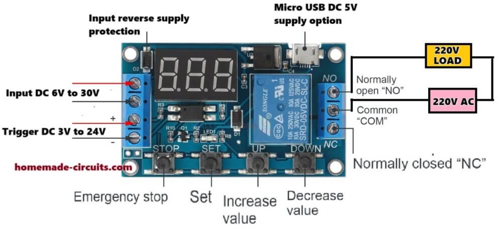
It has a trigger input with optocoupler so we do not get noise or wrong triggers. That trigger pin can take 3V to 24V DC.
There are many modes in this. Like we can make it delay ON or delay OFF or ON and OFF repeat (loop) with two different sets of timing outputs.
We can set time very easily using the small buttons. Timing ranges are:
From 0.1 sec to 99.9 sec (good for short delay)
Or 1 sec to 999 sec
Or 1 minute to 999 minutes (long delay)
We can power it using 6V to 30V DC from outside adapter or battery. Or we can even use USB 5V.
There is a relay inside. It can handle 10A at 125VAC or 30VDC, enough for small appliances.
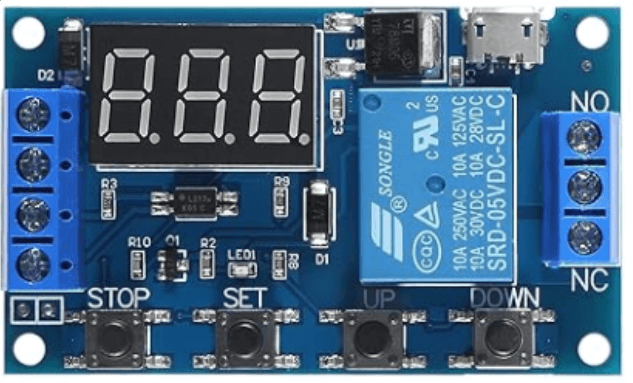
We can see stuff on the 3-digit LED screen and use 4 small buttons to program or change modes.
Different Modes – What We Can Do with This
Now we got 3 main working modes in this module. Let us understand them:
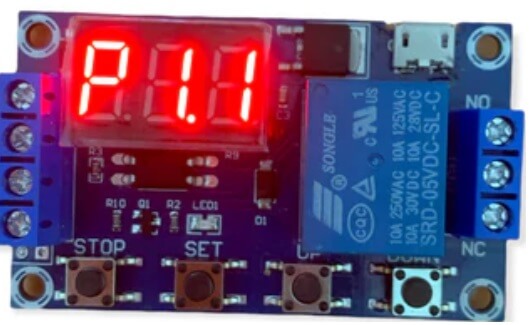
- P1.1 → Delay ON mode
So here when we give trigger, then timer waits for the time we set and then turns ON the relay. Like if we set 5 sec then after trigger it waits 5 sec and then turns ON the thing.
- P1.2 → Delay OFF mode
This one is opposite. When we give trigger, then relay turns ON immediately but then it waits for set time and then turns OFF. Like it stays ON only for that time.
- P1.3 → Loop or Cycle mode
This is for making ON and OFF repeat forever. We can set ON time and OFF time. Then it turns ON for that much time then OFF then again ON, repeat.
How to Wire and Connect This Thing
We have some terminals and pins:
Power: We give 6 to 30V DC on VCC and GND. Or just plug USB cable, it works with 5V also.
Trigger Input: This pin waits for 3 to 24V DC signal. Can come from switch, sensor, or microcontroller like Arduino.
Relay Output: We get 3 points – NO (Normally Open), COM, and NC (Normally Closed). So we connect our load like fan, bulb, or motor there.
Technical Details
| Parameter | What It Means |
|---|---|
| Voltage | Give 6 to 30V DC, or 5V USB |
| Trigger | 3V to 24V DC signal needed |
| Relay | Handles up to 10A at 125/250V AC or 30V DC |
| Time Range | 0.1 to 999 minutes depending on mode |
| Current | Normally 20mA, when relay ON it takes 60mA |
| Size | Around 62mm x 38mm x 17mm |
Where We Can Use It
- Automatic machine ON/OFF timing
- Light control for night time
- Motor pump timing control
- Robotic arm or motor actuation
- Incubator egg turning timing
- Toilet fan or exhaust fan auto OFF
- Voice module or sound box trigger timing
- Simple DIY delay systems
How to Program This Timer
Step 1: Power It Up
Connect 5V through USB or use 6V to 30V DC on the screw terminals (left side).
The 3-digit LED display should light up and show some numbers like 000.
Step 2: Enter Mode Selection
Now we want to select what type of timer function we want (P-1.1, P-1.2, etc). Here is how:
Press and hold the SET button for 2 to 3 seconds
Display will now show something like P-1.1
Use UP or DOWN buttons to scroll through the different modes:
P-1.1 = Delay ON
P-1.2 = Delay OFF
P-1.3 = ON/OFF loop mode
(some versions may have up to P-1.4)
Once your desired mode is showing then press SET again to go to time settings
Step 3: Set the Time Values
Now this depends on the mode you selected. I will show for P-1.3 (Loop mode) because it has all 3 settings (OP, CL, LOP).
Lets go:
After pressing SET again on P-1.3, then display shows OP → this is the ON time
Press SET once → now it shows number (like 005)
Use UP / DOWN to adjust ON time
Press SET again to lock it in
Now it shows CL → this is the OFF time
Press SET, adjust number, press SET again
Then it shows LOP → this is how many times it repeats the ON/OFF cycle
You can set from 1 to 999
If you want infinite loop then just set it to --- using DOWN until you see dashes
Press SET to confirm
Step 4: Try it Out
After all the settings now press STOP once to exit and save settings.
Now when you trigger the input (or auto trigger depending on mode), it will work like:
ON → wait OP time
OFF → wait CL time
Repeat for LOP times (or forever if infinite)
It saves settings in memory, so even after power goes OFF it still keeps them saved.
Quick Button Functions:
| Button | What it Does |
|---|---|
| SET (short press) | Move between OP, CL, LOP settings |
| SET (long press) | Enter mode select (P-1.1, etc.) |
| UP / DOWN | Increase or decrease values or change mode |
| STOP (short press) | Exit and save settings |
| STOP (long press) | Turn relay ON or OFF manually (test mode) |
Can this timer work like a 2 step timer with two independently adjustable ON OFF timing ranges?
YES it can do two ON/OFF steps — but not fully independent
When we use Mode P1.3 (loop mode), then we can set:
OP = ON time
CL = OFF time
LOP = how many times to repeat the cycle (can also be set to infinite)
So it will do like:
Turn ON → wait OP time → Turn OFF → wait CL time → repeat againThis already gives us 2 adjustable times — one for ON, one for OFF. So yes it does 2-step timing.
But now the limitation…
If you are thinking of something like:
First ON for 5 seconds
Then OFF for 2 seconds
Then ON again for 10 seconds
Then OFF for 6 seconds
… (and so on with different timings)
Then NO, it cannot do this directly because it only has one OP and one CL setting. So it is always same ON time and same OFF time for each cycle.
Workaround ideas:
If you want truly two separate ON-OFF sequences with different durations then you can:
Use two modules — one after the other. First module handles first ON/OFF, then second module starts after that to handle different ON/OFF.
Or connect it with a small microcontroller like Arduino — that can trigger this timer module with different delays in software.
Summary:
| Want | Can 35238-MP Do It? |
|---|---|
| 1 ON and 1 OFF with adjustable time? | ✅ Yes |
| Infinite ON/OFF cycle with fixed time? | ✅ Yes |
| Two different ON/OFF durations in same run? | ❌ Not directly |
| Separate 2-step control? | ❌ Not with one module |
| Use two modules for separate steps? | ✅ Possible |
Conclusion
So that is all. This 35238-MP timer is really useful, very flexible. Just need to learn how to set it and then it can do timing job like a pro.

Questions & Answers
HI Swagatam. Unfortunately I could not make the timer switch on. If I manually switched it, the program turned on and worked fine (P2.1), but when I just apply power to the unit it does not switch on. I enclosed by email a couple of photos of how I hooked it up, based on your suggestion. Regarding using mode P3.2 — unfortunately it seems to go to OP first and then CL mode. I need to go to CL first, then OP. I’d appreciate any advice you may have. Thanks.
Hi Joe,
the jumper from vcc to trigger failed because the timer chip boots up slow and misses the signal… it needs a pulse AFTER it turns on, not at the same exact microsecond.
To fix it, keep your settings on P2.1 (CL = 1 min delay, OP = on time), then put a 10k resistor between VCC+ and Trigger+, and a 10uF capacitor between Trigger+ and GND.
When you power on, that capacitor holds the trigger low for a split second while the chip boots, then lets the voltage go high….this tricks the board into thinking a switch was pressed right after bootup, so P2.1 starts automatically every time.
Thanks so much for the help, Swagatam! When I’m back in the shop I’ll do this and get back to you. Thanks again!
You are most welcome Joe, do let me know how it goes, and if you have any issues with this design..
I’m having difficulties programming my 35238-MP Timer Module. Really all I need is the P2.1 setting because I just want to time a component on a board to turn on about a minute after everything else. I’ve tried most of the settings, but the only one I could get to work was 3.1.1. I’ve tried two timer units and the same thing, so I know it’s user error. I want the timer to begin functioning when my development board is turned on — no switch. I wired the timer module like the one on the bottom of page one on the “Valefod DC 6-30V Timer Relay Programmable
Delay Relay Module USER GUIDE(JZ-801)” pdf that’s on amazon. Do you have any suggestions? Thanks
Actually, these timers need a trigger signal to start P2.1. When you just turn on the power, P2.1 waits for a trigger pulse so nothing happens. That is why 3.1 worked. To fix it in P2.1 without adding switches, just bridge a jumper wire from VCC positive to the Trigger positive pin. That way power going in triggers it right away. Or just change it to mode P3.2 with CL set to 1 minute and LOP set to 1 so it delays automatically on bootup. Make sure the decimal point is set to minutes not seconds.
Thank you! Your assistance has been invaluable!
It’s my pleasure!!
Ok, thank you.
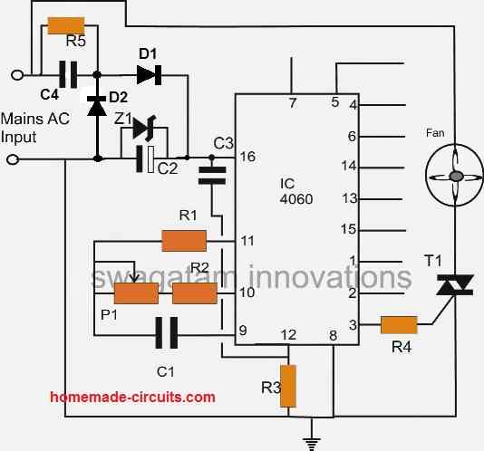
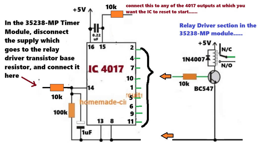
pls help me with the interconnection circuit between Timer module and the 4017 IC that can give 24 hours timer that can be auto resetting.
Sure, you can do the connections as given in the following diagram:
Thank once more, appreciated.
Now if I added the 4017 circuit I can set the timing to 2 hours on and 22 hours off continuously. and can be reset at any time.
Yes, by setting the timer to P1.3 → Loop or Cycle mode.
But 22 hours and 2 hours may not be possible….it should multiples of 4 hours or 3 hours….
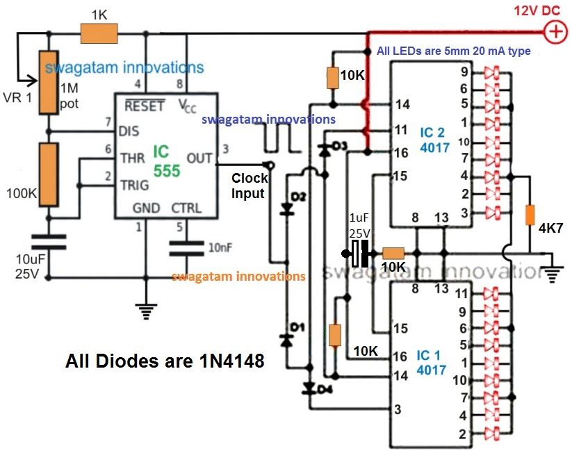
For multiple of 2, you may have to cascade two 4017 ICs in the following way:
Replace 555 clock inputs with your timer clock input, remove the output LEDs and configure the relay driver stage as suggested in the previous diagram…
This timer has 3 ranges…
From 0.1 sec to 99.9 sec
Or 1 sec to 999 sec
Or 1 minute to 999 minutes
Could either of its ranges be easily modified to count in one-hundredths from 0.01 – 1 sec?
Need it for controlling the current “pulse” of a spot welder where 0.2 seconds is slightly to short but 0.3 tends to burn a hole through the material.
Thanks
Unfortunately, No, the 35238-MP module cannot be modified easily to work from 0.01 to 1 sec.
You may have to go for a dedicated timer made for that range, preferably microcontroller based…
Arduino with MOSFET driver is the best and cheap option for that….
Hello, if I use this 25238-MP timer module and 4017 ic. can I increase the timing to 24 hours?
Hi, yes, you can do that…
OK, thank you!
hello good afternoon mr. Swagatam. i would like to know how this circuit works since i can’t see any microcontroller, pic or anything like that, how is it programmed?
You are right Carlos, even I could not find the microcontroller IC on the board, not even on the flip side of the board. It seems the only place for the uC to hide is under the display module….