• Skip to main content
  • Skip to primary sidebar

Homemade Circuit Projects

Need circuit help? Post them in the comments! I've answered over 50,000!

Blog | Categories | About | Hire Me | Contact | Calculators-online
You are here: Home / Lamps and Lights / How to Make 1 A Constant Current LED Driver Circuit


How to Make 1 A Constant Current LED Driver Circuit

Last Updated on June 1, 2026 by Swagatam 16 Comments

Table of Contents
  • About the IC MBI6651
  • Typical Application Areas of this device are:
  • Setting the output Current
  • Optimizing External Component Selection
  • Selecting the Schottky diode
  • Selecting the capacitor
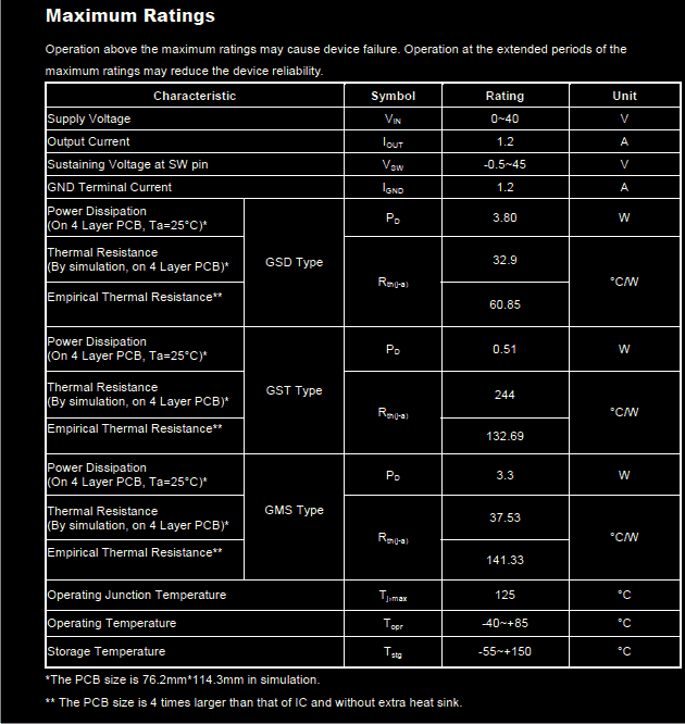
    • The basic operating parameters are given below:

In this article I have explained a simple 1 amp constant current LED driver circuit using the IC MBI6651 from MACROBLOCK. The IC has been specifically designed for operating high power LEDs safely by providing a constant current output. The circuit includes very few external components and therefore becomes very easy to assemble at home.

About the IC MBI6651

The IC MBI6651 is a high efficiency, step down DC to DC converter chip capable of driving high power LEDs at a safe 1 Amp constant current.

The IC requires just four passive external components for making it functional.

The output current of the IC can be externally set by selecting the appropriate resistor value.

The IC also features a PWM controlled dimming control of the connected LEDs.

Some of the other outstanding features of this IC includes UVLO meaning under voltage lockout, over temperature shut down, LED open circuit protection and LED short circuit protection, all these ensure complete safety to the IC from wrongly configured output loads.

Typical Application Areas of this device are:

Automotive decoration and illumination

LED flood lights using high intensity, high power LED.

The IC also can be used as a constant current source in particular circuit applications.

Setting the output Current

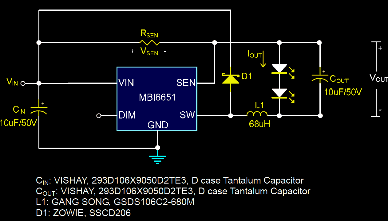
The output current of the IC is fixed through an external resistor Rsen. The output current Iout and the adjustment resistor Rsen has the following relation:

Given Vsen=0.1V

Rsen=(Vsen/Iout)=(0.1V/Iout)

Where Rsen is the value of the external resistor. This resistor is connected across the pin outs SEN and Vsen of the IC.

The optimum current with Rsen 0.1 Ohms is 1000 mA or 1 Amp.

Optimizing External Component Selection

Inductor: Two issues specify the inductor type, the switching frequency and the ripple current. The involved calculation can be written as:

L1>{Vin - Vout - Vsen - (Rds(on) * Iout)} * D/fsw * delta.IL

where, Rds(on) is the on-resistance of the IC's internal MOSFET. The value is typically around 0.45 at 12V

D is the duty cycle of the IC, given as D = Vout/Vin

fsw is the switching frequency of the IC

While designing the inductor for the given circuit, along with the inductance the saturation current must also be taken into account,because these are two basic factors which typically affects the overall performance of the circuit.

The rule of thumb, the saturation current of the inductor should be selected 1.5 times greater than the LED current.

Moreover, selecting high values for the inductance provides better line and load regulation.

Selecting the Schottky diode

The diode D1 shown in the circuit diagram basically acts as the flywheel diode for nullifying the inductor back emf during the periods when the LED is switched OFF.

The diode must be selected with the following couple of important characteristics:

It should have a low forward voltage rating and maximum possible reverse voltage tolerance.

Selecting the capacitor

The general rule is always to select a capacitor value with a voltage tolerance 1.5 times higher than the supply voltage.

Preferably, a tantalum capacitor should be selected because these have high capacitance and low ESR characteristics.

The proposed circuit of 1 Amp constant current LED driver circuit is given below:
The basic operating parameters are given below:
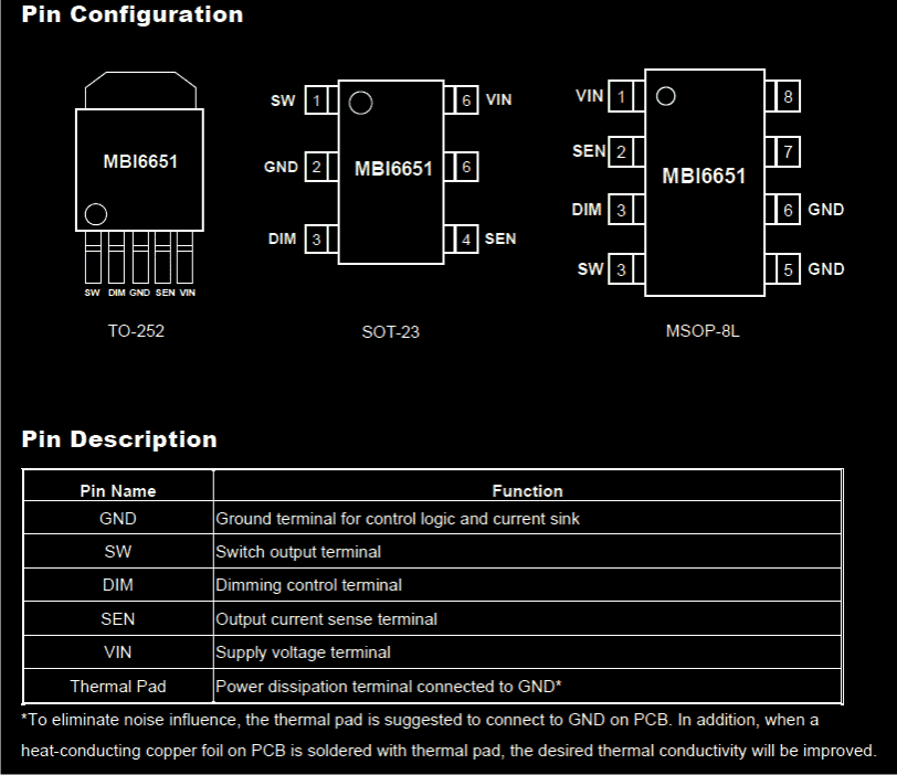
Pin Out Specs:
Courtesy: https://www.homemade-circuits.com/wp-content/uploads/2012/04/mbi6651.pdf

You'll also like:

  • High quality 3 watt rgb led withSimple Scrolling RGB LED Circuit
  • LED LDR blinker GIFBlinking LED Circuit using LDR and Resistors
  • solarfishaquariumlightoptimizercircuit3 Automatic Fish Aquarium Light Optimizer Circuits
  • bow tie LED circuit sound activatedBlinking LED Bow Tie Circuit

Filed Under: Lamps and Lights Tagged With: Constant, Current, Driver, LED

About Swagatam

I am an electronics engineer and doing practical hands-on work from more than 15 years now. Building real circuits, testing them and also making PCB layouts by myself. I really love doing all these things like inventing something new, designing electronics and also helping other people like hobby guys who want to make their own cool circuits at home.

And that is the main reason why I started this website homemade-circuits.com, to share different types of circuit ideas..

If you are having any kind of doubt or question related to circuits then just write down your question in the comment box below, I am like always checking, so I guarantee I will reply you for sure!


Previous Post: « Simple Car Shock Alarm Circuit
Next Post: Using Triacs for Controlling Inductive Loads »

Reader Interactions

Questions & Answers

Total Posts: 16
Newest Oldest
Unknown
July 24, 2014 • 12 years ago #24533

Hi
Can you post a circuit which takes input from user and keeps the current constant as per input? Range is 1 micro amp to 15 micro amp. Volt 10 to 30.

svarbanu

Reply
SwagatamAdmin
July 25, 2014 • 12 years ago #24557

In uamps it could be difficult….not sure.

Reply
Subrata Bera
July 27, 2014 • 12 years ago #24616

Hello Swagatam, you have a really nice and informative blog there. Thanks for sharing all your learning with the world. It really help us a lot.

I need a little suggestion with constant current circuits. Could you please share the details of other such chips in the market which can take universal AC input and gives a constant current (adjustable) for various voltage requirements (Example : LC5226D). The availability of the components should be considered as finding such chips can be a really tedious job.

Thanks & regards,
SB.

Reply
SwagatamAdmin
July 28, 2014 • 12 years ago #24630

Hello Subrata, thank you very much!

I don't think there are such ICs which might be commonly available in the market, because nowadays SMPS circuits have become an easy alternative for achieving the same, therefore all today depend on SMPS designs which are plentifully available in the market. I too have posted many SMPS design which could be easily built at home.

Regards.

Reply
Ronald Beck
January 18, 2018 • 9 years ago #57756

I’m looking to make a LED device that can be used as photographic flash with a very short duration 0.1 ms or less (ns range would be really cool). I plan to use an arduino uno for the trigger circuit. Could the MBI6651 circuit above be use/modified for this purpose using an appropriate power supply? Thanks for any help you can provide.

Reply
SwagatamAdmin
January 18, 2018 • 9 years ago #57765

If you have an easy access to this IC then definitely you can use it, although any simple LM317 CC/CV circuit would do the job as efficiently

Reply
Sayyed Yaseen
October 16, 2020 • 6 years ago #83617

Hello Swagatam,

I am also an electronic engineer, I want to control LED strip light.
But the brightness is not same through out the strip its brightness is low at the last end. Strip length is 5-10meter.

Please recommend me to achieve the same brightness.

Reply
SwagatamAdmin
October 16, 2020 • 6 years ago #83627

Hello Sayyed, please provide detailed information about the strips, are these separate LED strips, or all the LEDs connected in one single strip, and are the LEDs and the resistors on the strip have same specifications or different??

Reply
Paul
March 4, 2021 • 6 years ago #87530

I’m interested in building your 1amp MB16651 Macroblock constant current circuit but I can’t find where I can buy the part. Checked Digikey and Mouser. Any suggestions would be appreciated. Many thanks Paul

Reply
SwagatamAdmin
March 5, 2021 • 6 years ago #87552

May be the IC is discontinued, but you can find many similar variants, such as the following:

DC to DC Converter Circuits using SG3524 [Buck, Boost Designs]

Reply
Paul
March 6, 2021 • 6 years ago #87582

Hi Swagatam
Eventually not only did I find the distributor but he had the parts in stock and sent me 12 free of charge! Mnay thnaks for you help Paul

Reply
SwagatamAdmin
March 6, 2021 • 6 years ago #87590

That sounds amazing Paul! glad you could procure the parts finally, wish you all the best!

Reply
Marcel Dugas
October 13, 2021 • 5 years ago #101162

Hello,

I am wondering what kind of dimming circuit is necessary to work with this schematic; PWM or 0-10V?

Thank you,

Marcel

Reply
SwagatamAdmin
October 13, 2021 • 5 years ago #101173

Hello, according to the explanation it is PWM input that will control the dimming.

Reply
Aliasgar
December 12, 2021 • 5 years ago #107059

Hi Swagatam can you please give me a method to change in normal DOB of 9W from 220V AC to run on 110V DC
Or any compact circuit diagram to run 7 to 11 W LED on input 90V DC to 140V DC preferably without coil.

Reply
SwagatamAdmin
December 13, 2021 • 5 years ago #107106

Hi Aliasgar, how many LEDs are there in series, and what is specification of each LED. Please provide this data, I will try to figure it out.

Reply

Need Help? Please Leave a Comment! We value your input—Kindly keep it relevant to the above topic! Cancel reply

Your email address will not be published. Required fields are marked *

Primary Sidebar

My YouTube Channel

Circuit Simulator: Draw and Simulate Schematics

circuit simulator image


Categories

  • Arduino Projects (95)
  • Audio and Amplifier Projects (134)
  • Automation Projects (18)
  • Automobile Electronics (104)
  • Battery Charger Circuits (90)
  • Datasheets and Components (109)
  • Electronics Theory (151)
  • Energy from Magnets and Earth (43)
  • Games and Sports Projects (11)
  • Grid and 3-Phase (20)
  • Health related Projects (27)
  • Home Electrical Circuits (13)
  • Indicator Circuits (16)
  • Inverter Circuits (98)
  • Lamps and Lights (161)
  • Meters and Testers (72)
  • Mini Projects (28)
  • Motor Controller (68)
  • Oscillator Circuits (30)
  • Pets and Pests (15)
  • Power Supply Circuits (91)
  • Remote Control Circuits (50)
  • Security and Alarm (65)
  • Sensors and Detectors (107)
  • SMPS and Converters (46)
  • Solar Controller Circuits (62)
  • Temperature Controllers (44)
  • Timer and Delay Relay (51)
  • Voltage Control and Protection (44)
  • Water Controller (37)
  • Wireless Circuits (31)


Subscribe to get New Circuits in your Email


Other Links

  • Privacy Policy
  • Cookie Policy
  • Disclaimer
  • Copyright
  • Videos
  • Sitemap

People also Search

555 Circuits | 741 Circuits | LM324 Circuits | LM338 Circuits | 4017 Circuits | Ultrasonic Projects | SMPS Projects | Christmas Projects | MOSFETs | Radio Circuits | Laser Circuits | PIR Projects |


Recent Comments

  • Swagatam on Adjustable Voltage Regulator Circuit using LM324 IC with Over Current Protection
  • Swagatam on Inverter Circuit with Feedback Control
  • Swagatam on Inverter Circuit with Feedback Control
  • Swagatam on Proximity Detector IC CS209A Pinouts – Datasheet Explained
  • PRAFUL WANDHARE on Proximity Detector IC CS209A Pinouts – Datasheet Explained

Social Profiles

  • Twitter
  • YouTube
  • Instagram
  • Pinterest
  • My Facebook-Page
  • Stack Exchange
  • Linkedin

Calculators

  • ZVS Induction Heater + Tank Calculator Tool
  • Zener Diode Calculator
  • Wire Current and Thickness Calculator (Ampacity Calculator)
  • Voltage Divider Calculator
  • Transistor Base Resistor Calculator
  • Transistor Astable Multivibrator Calculator
  • TL431 Calculator
  • Solar Panel, Inverter, Battery Calculator
  • Ferrite Core Air Gap Calculator Tool
  • Parallel MOSFET Calculator Tool: How to Connect MOSFETs in Parallel Safely
  • LC Resonance Calculator for EV Battery Charger Circuits
  • LED String Series Resistor Calculator
  • PFC (Power Factor Correction) Calculator Tool: 3kW
  • Passive Power Factor Correction (PFC) Calculator
  • LM567 IC Calculator Tool
  • SMPS Flyback Boost Converter Calculator
  • Shunt Resistor Calculator for Ammeters
  • SCR and Triac Gate Resistor Calculator
  • Battery Back up Time Calculator
  • Boost Converter Calculator (Non-Isolated)
  • Bootstrap Capacitor Calculator
  • Buck Converter Calculator
  • Buck-Boost Converter Calculator
  • Capacitance Reactance Calculator
  • DCM Flyback Transformer & Wire Gauge Wire Size Calculator Tool
  • Filter Capacitor Calculator
  • IC 4047 Calculator (Frequency and PWM)
  • IC 4060 Calculator
  • IC 555 Astable Calculator
  • IC 555 Monostable Calculator
  • IC SG3525, SG3524 Calculator
  • Inductance Calculator
  • Induction Heater Inductor and Resonant Frequency Calculator
  • Induction Heater Work Coil Calculator
  • Inverter LC Filter Calculator
  • LC Resonance Calculator
  • LED Current Calculator
  • LM317, LM338, LM396 Calculator
  • NAND/NOT Gate RC Values Calculator
  • NOT, NAND Gate Frequency Calculator
  • Notch Filter Calculator Tool
  • Ohm’s Law Calculator
  • Phase Angle Phase Shift Calculator
  • Power Factor (PF) Calculator
  • RC Filter Calculator
  • Reactance Calculator
  • Sine Table Calculator for SPWM Arduino Code
  • Small Signal Transistor(BJT) and Diode Quick Datasheet
  • SMPS Calculator for Toroidal Ferrite Transformers
  • SMPS Flyback Transformer Calculator – Design by Target Duty Cycle
  • TL431 Calculator
  • Op-Amp Hysteresis Resistor Calculator

© 2026 · Swagatam Innovations