In this post I have explained how to make a simple homemade walkie talkie circuit using ordinary FM transmitters and FM radios. It's a perfectly tested design by me.
I could talk with my nephew who stays on first floor through a pair of these transmitters with crystal clear transmission.
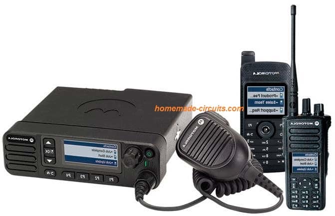
Overview
In one of my earlier post I will comprehensively explained the making of a compact walkie talkie design, however I found that many new hobbyists and school students found the design difficult to adjust and succeed due to its rather complex and the associated strict parameters,
In this post we try to design a walkie talkie using discrete transmitter modules and then tune them to different frequencies such that the units are able transmit and exchange the conversation across both the sides without interfering with their own receive modules.
For the FM transmitters we select the design which was earlier discussed in our wireless speaker circuit, the main reason being its ability to produce high power output, which enables the circuit to transmit the data over much longer distances compared to the other smaller FM transmitters designs.
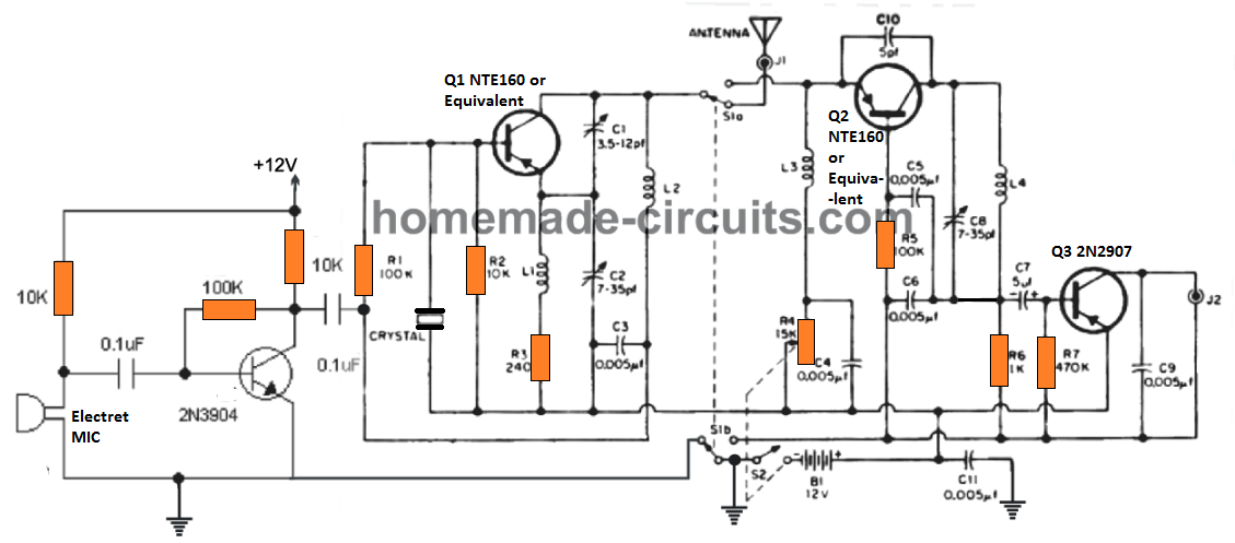
Want to learn how to build a small transceiver circuit? The following post will walk you through all the details:
High Range Design
As you can see the design is different from the usual single transistor concepts. Here the design incorporates a 3 transistor design along with a center tap antenna coil. This enhances the power output of the transmitter to a great extent, approximately 4 times more than the single transistor version.
With this special patented design you can enjoy communicating with your friends in your multistorey apartment, across the highest number of floors.
The minimum distance this unit can cover is 50 to 100 meters.
The range of a single transistor circuit cannot be over 30 meters. Check it yourself!
The main objective here is to get a reasonable distance of wireless communication facility.
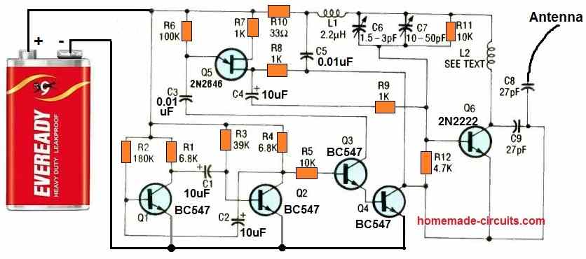
Circuit Diagram
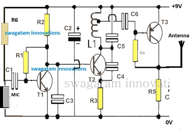
How the Transmitter Works.
The Transmitters: First you will have to construct two of these identical transmitter circuits as shown below:
The operating principle of this powerful little transmitter can be understood from the following points:
The MIC converts the voice signals into electrical signals which is further amplified into high amplitude low current signals by T1.
This amplified signal is fed to the base of T2 which basically forms a frequency generator stage with the help of L1, C4, C5 and C3. Together this stage forms a regenerative oscillator which resonates in the range of 50 to 200MHz depending on the setting of the relevant LC tank components settings and values.
The amplified voice signals from T1 collector gets effectively modulated over the T2 high frequency carriers waves and this modulated signal is applied to the base of T3 for enriching it with high current.
T3 basically ensures that the modulated voice signals become significantly powerful with current, and is able to be transmitted to much longer distances with the help of an appropriate antenna.
The antenna does not need to be anything special, rather an ordinary 2 feet long flexible wire will be quite enough to enable the transmission to reach over 200 meter distance.
Along with these two transmitters you will also need a couple of FM receiver units or simply FM radios, so that the transmitted signals can be received by the respective radios and a conversation over the two sides can be completed.
Thus we basically have two sets of transmitter/radio through which two individuals are able to exchange their thoughts by speaking over the respective MIC inputs.
Each of the Tx/Rx sets must have mismatched frequency while the opposite side Tx/Rx must have accurately matched frequency response, in other words the opposite side Rx/Tx must be optimally tuned with a given frequency value which must be sufficiently different from the tuned frequency value of the other opposite Tx/Rx pair.
For example if one opposite Tx/Rx pair is tuned at 90MHz, the other could be tuned at 100MHz frequency just to make sure that each of the walkie talkie unit doesn't interfere with their own set frequency value.
Using an FM Radio as the Walkie Talkie Receiver (Rx)
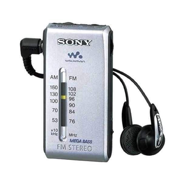
The radio could be any type depending on the user's choice, but preferably it must have a convenient frequency adjustment button such as a knob or a up/down keys.
Your smart phone FM radio would also work but the range would be significantly less than conventional radio having a telescopic antenna. If you intend to operate the units for a room to room conversation then probably your phone would do the job as the receiver,
How to Tune and Test The Walkie Talkie Pairs
First make sure that your transmitter is correctly built and is actually transmitting the signals. To do this keep an FM radio at around 2 meters away from the Tx circuit, switch ON the Tx and the radio, and start adjusting the frequency knob of the radio until you suddenly find a "dead" spot on the band.
Now tapping lightly on the MIC should generate a thudding sound on the radio speaker, confirming the transmission from the Tx unit.
After this, keep increasing the distance between the Tx and the radio and finally try finding the maximum possible distance that the units are able to interact optimally. This may be done by some trial and error and by some skillful fine tuning of the adjustments of the two counterparts.
Repeat the same for the other Tx/Radio pair and this will complete your homemade FM walkie talkie circuit.
Now it's just about keeping the oppositely tuned units across the two sides from where the conversation needs to be done, and then with some more adjustments you can finally get the conversation going with this simple homemade equipment.
If you have any doubts, please feel free to share them through your comments.
Parts List for the above shown transmitter
- R1 =1M,
- R2 = 2K2,
- R3 = 470 Ohms,
- R4 = 39K,
- R5 = 470 Ohms,
- R6 = 4k7
- C1 = 0.1 uF,
- C2 = 4.7 uF,
- C3, C6 = 0.001uF,
- C4 = 3.3pF,
- C5 = 10pF,
- L1 = It is a 7 turn coil made using 1 mm super enameled copper wire, having 6 mm diameter. The center tap is taken from 1st turn as shown below.
- T1, T2 = BC547B,
- T3 = 2N2907B
- MIC= electret MIC
L1 Coil Design
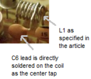
If you are having any confusions regarding the construction of this project contact me immediately, I'll help you through until your project is completed.
PCB Design
The PCB design for the proposed FM radio based walkie talkie circuit can be witnessed below:
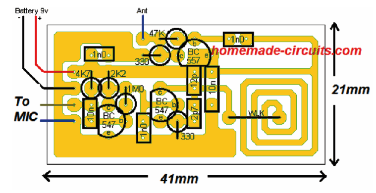

As you can see, the antenna coil is designed on the PCB itself, through a spirally laid track layout, having the exact required embedded inductance. Thus the circuit becomes truly compact as it does not depend on the traditional, cumbersome, manually wound copper coil.
The supply being 9V, it works with extra power ensuring that the conversation is distinctly clear even at distances over 150 meters, which other similar transmitter would simply fail to accomplish.
Make sure to use a 1 meter long flexible wire for the antenna, to get a distortion free walkie talkie experience.


Questions & Answers
How do we have to connect c7? the connection is not shown in diagram :/
please ignore it, it’s not there
Is the circuit tested?
tested!
how many volts are the capacitors?
normal rating, that you get in the market for the respective categories!
…it should be higher than 12V
Ok thank you, and also, what is L1 please?
I have updated the details of L1 in the article, please check it out.
Engr. Swagatam,thanks so much. Pls I need to build a multi dual tone frequency circuit.,..or any similar circuit.
2..I need a circuit that can record voice and replay it at any time… Pleas help thanks
For a multitone circuit, use a IC 555 astable and adjust it frequency through sa pot, or the same can be done using a 4060 IC.
second circuit is given here:
https://www.homemade-circuits.com/?s=voice+record
Hello Swatagam,
I’ve tried to build your circuit, but I’m having problems.
The microphone doesn’t work at all (even when I replace it bij a stereo microphone), so I’ve connected a tone generator to the transmitter. This way I do get something of a transmission, but it is very dependant of the orientation of the antenna, and quite weak. The signal is also very much disturbed by regular radio transmissions.
Do you have an idea what could be wrong?
Thank you in advance from the Netherlands!
Hello Annes, The mic should be an electret mucrophone, as given here:
https://www.homemade-circuits.com/how-electret-microphone-works/
this circuit has been thoroughly tested by me and for me it worked very nicely. Make sure the coil is built exactly as shown. I could transmit music upto 3rd floor using this circuit in my building. And when music is transmitted this circuit becomes even more powerful and long distant.
If possible I’ll try to post a video soon.
Can you please make video for the connection of L1 and its center tapping?…its critical part
It is already shown in the L1 coil design, you will have to do it exactly in the same way
Lista de peças diferentes da placa PCB. Diferenças nos transistores, capacitores com outros valores?
Is there any alternative for L1 and centre tape capacitor??
What is so difficult in it? It is a straightforward coil. You can try the PCB track embedded coil otherwise…
Actually, I have to make schematic of this circuit for project report and proteus doesn’t allow to connect wires in the middle of any component.(L1)
In that case you can remove the entire T3 stage and its associated components…but this may cause the range to become quite less.
Good day sir…engineer I made this circuit is working but is not going far as I need….I want it go upto 10km pls help me sir thanks
Thanks Sunshine, I am glad its working for you, however it is meant for just around 500 meters, for 10km you will need a more sophisticated design such as as this:
https://www.homemade-circuits.com/27-mhz-am-fm-transmitter-circuit-for-citizen-band-communication/
Dear inventor. .. thank you so much for your tutorials and help… my question is …is it possible to change some components to convert it to work on HAM range? Or can it be converted to a portable HAM?
Hello, sorry that’s not possible, however I have a few good HAM radio circuits which I’ll be publishing soon…so please stay tuned.
Hi do you have the computations on how you have come up with this design? If yes I hope you could share them 🙂
Hi, sorry, I do not have the calculations for this project!
Hello Mr.Swag my question ,can i use variabel capacitor for change C5?
Hi Sarwana, yes you can do it
Mr.Swag , T3 = 2N2907B can change with bc557 ? Thanks
yes you can try that!
Can I get PCB for this transmitter? Pls mention cost & How to order?. Thanks &Regards.
Sorry, we don’t sell PCBs or electronic materials from this website!
Salam,
Hi there,
I’ve bought a walkie talkie toys for my two little girls, but they are too bad, I hope to get any help from you how to improve there electronic-circuit, and make my daughters happy.
Thanks.
Hi, improving the circuit can be done only if you know the whole working of the circuit, other wise it can be difficult. The external way is to increase the antenna length by adding a feet long wire to the existing antenna.
How can i increase the range of this one?
By the increasing the antenna length….
hi I’m Nicolas from South Africa I am really interested in learning electronics, so I would like to know don’t you have a YouTube channel where you make tutorial videos about electronics, I would like to subscribe.
Hi, I have a Youtube video channel, but there are no tutorials, only electronic experiments
Can You please tell me About L1 which material is Used Thickness of wire number of Turns Or length of Wire
In walkie talkie using FM Radio
It is given in the parts list. Please check it.
beautiful explanations, thank you! I enjoy your projects.
Could you use this circuit for a transmitter in the 863-865 Mhz range?
It can be probably done by reducing the L1 number of turns, or by reducing the C5 value.
Sir you mentioned two identical circuits need to be built…fine but how do we set tx 2 circuit at some other frequency than the one used by tx 1 circuit
Hi Yashwin,
You can set the tx1 and tx2 frequencies using an FM radio. Set the frequencies such that they are received by the radio at two different locations on the band. For example tx1 can be fixed at 95 MHz, and tx2 can be set at 101 Mhz.
what does mean R2=2K2 and R4=4K7 ?? what are the values of the following resistor ? thank you at first .
2k2 = 2.2k
4k7 = 4.7k
hi sir why did you mention two different value of parts I mean in schematic and pcb desingn.
which of them is true for example in sch we have resistor 470 ohm but in pcb 330 ohm or in sch we don’t have capacitor 12pf and 2.7 pf but in pcb design we have.
thanks for your help.
Hi m.r, actually both the versions will work, but I would recommend you to follow what’s given in the PCB design, which is easier to implement.
thanks for your answer but witch of them can cover more distance and how much?