An AC mains high/low cut-off device will cut off or disconnect the mains supply from home electrical whenever a high voltage or low voltage situation is detected. In this way it ensures total safety to the home wiring and appliances from fire hazards, due to abnormal over voltages, brown outs or low voltages.
In this article I have explained 3 accurate automatic over and under voltage cut out circuits can be made at home for protecting the domestic appliances from sudden dangerous high and low voltage influxes.
The first cut-off circuit discusses a transformer based circuit with 4 LED indicators, the second and third voltage protection circuits use only a couple of op amps, and work without a transformer, while the fourth concept explains a transistor based cut off circuit.
All of these units can be installed at home for controlling over and under voltage cut off protection.
1) High/Low Mains Voltage Cut-off with Indicators
The AC mains high and low voltage cut off circuit I have explained in this article is very easy to build and yet very reliable and accurate.
The circuit utilizes a single IC LM 324 for the necessary detection and instantly switches the relevant relays so that the connected loads are isolated from the dangerous inputs.
The circuit also provides visual indications of the respective voltage levels during any instant.
The following circuit utilizes a transformer for powering the circuit
Circuit Diagram
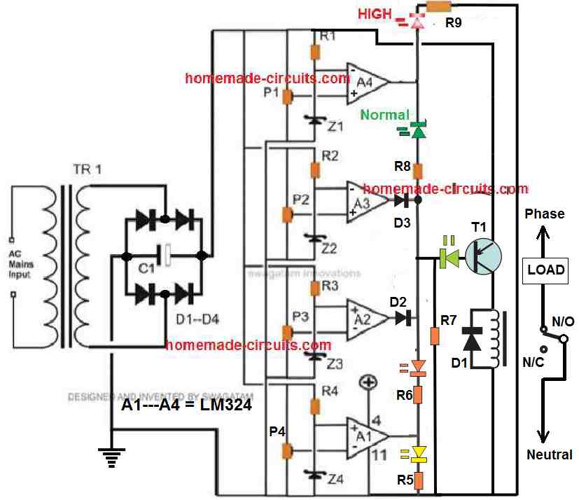
Parts List for the proposed high, low mains voltage protector circuit.
- R1, R2, R3, R4, R5, R6, R7, R8, R9 = 4K7 = 9
- P1, P2, P3, P4 = 10 K Presets = 4
- C1 = 1000 uF/ 25 V = 1
- Z1, Z2, Z3, Z4 = 6 Volts, 400 mW = 4
- D1 = 1N4007 =1
- D2, D3 = 1N4148 = 2
- T1 = BC557B = 1
- LED = All are 20 mA, 3.3 V = 5
- Transformer = 0 – 12 V, 500 mA = 1
- Relay = SPDT, 12 Volt, 400 Ohm = 1
Circuit Operation
The present design of a high voltage and low voltage cut off circuit is not only highly accurate but also provides visual indications regarding the relevant voltages insteps.
The accuracy is so high that virtually the thresholds can be separated and sensed within 5 volts range.
The incorporation of opamps in the circuit equips it with the above feature and therefore the whole idea become very much reliable.
Let’s understand the circuit in details:
How the opamps Operate as Comparators
The opamps, A1, A2, A3, A4 are obtained from a single IC LM324, which is a quad opamp IC, means consists of four opamp blocks in one package.
The IC is outstandingly reliable and easy to configure and hardly poses a problem with its functioning, in short it has robust specs and is too flexible with most of the configurations.
The four opamps are rigged as voltage comparators. The inverting inputs of all the opamps are clamped to a fixed reference value of 6 volts which is done through a resistance/zener network for each of the opamps discretely.
Op amp A2 and A3 are configured as window comparators, meaning the outputs of both these opamps will be zero volts or logic low, as long as the input AC is within the normal range, as set by the presets P2, P3.
A2 controls the low voltage cut-off while the A3 monitors the high voltage cut off point.
The remaining opamps A1 and A4 are simply rigged as voltage indicators along with the associated yellow, orange, green, red LEDs.
How to Setup
Setting up of the presets P1 to P4 are implemented by first evaluating the various DC levels that would match the corresponding AC mains voltage levels.
This is elaborately explained under the "Calculating the Cut-off Thresholds" section below.
Let's assume the DC supply voltage from the bridge is 12 V when the mains input AC is at 220 V.
Next, let's suppose we want to illuminate the yellow LED at 10 V in response to 183 V, orange LED at 11 V in response to mains 201 V, top green LED at 14.5 V corresponding to 265 V input AC, and RED LED at 15.5 V corresponding to 284 V mains input.
Initially keep the transformer disconnected, and the relay also disconnected from the transistor.
Using a variable power supply, set a voltage of 10 V across the op amp circuit, and adjust the P4 preset until the yellow LED just illuminates.
Next, increase the supply to 11 V, this should instantly shut off the yellow LED. Now tweak and shuffle the P3 preset until the orange LED just light up.
Increase the voltage supply to 12 V, this should instantly shut off the orange LED.
Next, increase the DC supply to 14.5 V, tweak and shuffle P2 until you find a point on the preset P2 where the green LED at the transistor base just shuts off, but reducing the voltage slightly below 14. 5 V quickly illuminates it.
Finally, adjust the DC level to 15.5 V, which should switch OFF the transistor base LED. After this, tweak and shuffle the preset P1, until you see the red LED just illuminating.
This completes the Setting up procedures, now you can connect the relay with the transistor collector, and the transformer input with the mains, and expect the circuit to work exactly as per the settings.
2) Using Two Op amps Only
After some analysis, I realized that the above high, low mains voltage cut off protector circuit could be simplified into a much easier version using just a couple of op amps.
Please refer to the diagram given below; it's self-explanatory and very simple to understand.
However if you have problems understanding it, shoot me a comment.
Caution: Visually Conflicting Issues
All the op amp based diagram I have explained below have a few visually conflicting issues, which are I have explained below. Readers are requested to kindly take these issues into consideration and adjust the interpretation accordingly:
- The lower op amp is set to control the upper voltage limit.
- The upper op amp is configured to control the lower voltage limit.
- Preset P1 is designated for op amp A2.
- Preset P2 is designated for opamp A1.
As you can see the the designations of the parameters are conflicting with each other.
Except the above issue, the circuit is technically perfect and will work exactly as specified in the descriptions.
There are many versions of the high/low AC mains protection circuit included in the present article.
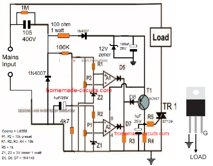
The first one below explains a capacitive powered version, using only two opamps and a triac.
Transformerless/Triac Version
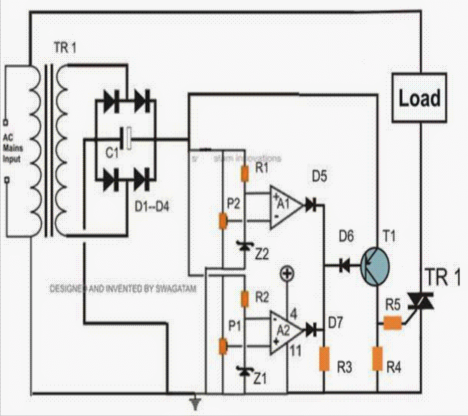
The transformerless mains high low voltage cut off circuit version of the above explained design can be visualized in the following diagram:
Warning: The below shown circuit is not isolated from mains AC. Handle with extreme caution to avoid a fatal mishap.
Using a Single Relay
If a single relay is intended to be used instead of a triac, the design could be modified as shown in the following figure:
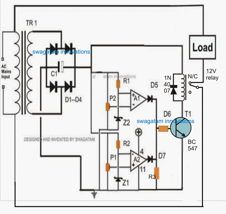
Please use a 22uF/25V capacitor across the transistor base and ground, just to make sure the relay does not stutter during the changeover periods...
Using PNP Relay Driver
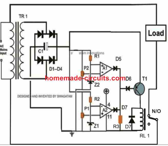
As shown in the given mains AC high, low voltage protector circuit, we can see two opamps from the IC LM 324 are used for the required detection.
The upper opamp has its non inverting input rigged to a preset and is terminated to the supply DC voltage, pin #2 here is provided with a reference level, so that as soon as the potential at pin #3 goes above the set threshold (by P1), the output of the opamp goes high.
Quite similarly the lower opamp is also configured for some voltage threshold detection, however here the pins are just reversed, making the opamp output go high with low voltage input detection.
Therefore, the upper op amp responds to high voltage threshold and lower op amp to low voltage threshold. For both the detections, the output of the respective op amp becomes high.
Diodes D5 and D7 make sure that their junction produces a common output from the opamp output pin outs.
Thus whenever any one of the op amp output goes high, it is produced at the junction of D5, D7 cathodes.
Transistor T1’s base is connected to the above diode junction, and as long as the opamps output remain low, T1 is allowed to conduct by getting the biasing voltage through R3.
However the moment any of the opamp output goes high (which may happen during abnormal voltage conditions) the diode junction also becomes high, restricting T1 from conducting.
Relay R1 instantly switches OFF itself and the connected load. Thus the connected load remains ON as long as the opamp outputs are low, which in turn can only happen when the input mains is within the safe window level, as adjusted by P1 and P2. P1 is set for detecting high voltage levels while P2 for the lower unsafe voltage level.
Calculating the Cut-off Thresholds
The basic idea is to make A2 output HIGH, when the mains AC goes above the higher mains voltage cut-off point, and to make A1 output HIGH when the AC mains input goes under the lower voltage cut-off threshold.
The outputs of A1, and A2 op amps are supposed to remain LOW, as long as the input AC stays within the stipulated normal voltage range.
The mains input AC voltage levels will be very linear with the DC output levels across the +/- lines of the circuit, or across the bridge rectifier output.
Therefore, the DC level across the bridge rectifier, applied to the circuit will vary linearly in response to the varying AC mains input.
This means that, we have to first check and measure the DC levels that exactly coincide or correspond to the upper and lower cut off thresholds of the mains AC.
This can be done in the following manner:
Remove the complete circuit from the bridge rectifier output, and check the DC voltage across the bridge rectifier through a DC voltmeter.
Let's say you find it to be 13.2 V, now quickly change the range of the meter to AC mains level and check the voltage at the AC mains side of the transformer. Let's say you find it to be 230 V.
This would mean that 230 V input AC produces an output DC of 13.2V.
Once the above info is confirmed, the corresponding upper and lower thresholds could be calculated through a simple cross multiplication, as I have explained below:
230/200 = 13.2/A
- Here, 230 represents the normal AC input voltage.
- 13.2 indicates the corresponding normal DC at 230 V input AC
- 200 is assumed to be the lower cut off threshold.
- A is the required DC corresponding to the 200 V lower cut off threshold
Solving the above gives us:
A = 11.47 V which is our lower cut-off DC at 200 V input AC.
Likewise, the upper cut-off DC can be found as:
230/260 = 13.2/B, here B is the upper cut-off DC corresponding to the 260 V high AC input.
Solving the above gives us:
B = 14.92 V, which is our higher DC cut-off voltage value, corresponding to the 260 V high AC voltage.
Setting up the Presets
Now, since we know the lower and the upper DC levels at which the relay needs to activate, we can set up the two presets accordingly, with the help of the following points:
- You will need a variable power supply for the setting power supply, which should be able to produce an adjustable output from lower than 10 V DC to a maximum of 15 V DC, or higher.
- First, adjust the above power supply output to the lower cut off level of 11.47 V or 11.50 V
- Disconnect the opamp/relay circuit from the bridge rectifier circuit and connect this 11.50 V with the op amp.
- Connect a DC voltmeter across A1 op amp output and the ground line.
- Tweak and adjust the P2 preset until you find A1 output becoming HIGH.
- Now adjust the input supply DC to slightly over 11.50 V, let's say to 11. 90 V.
- This should immediately cause the A1 output to turn LOW.
- Once you see this you can confirm that the lower cut-off level corresponding to the 200 V and below is set.
- Now, increase the input DC level to the upper cut-off level of 14.92 V.
- With the DC voltmeter now connected across the A2 output and the ground line, start adjusting and tweaking the preset P1, until you find the A2 output turning HIGH.
- Once you find the output turning HIGH at 14.92 V, decrease this level slightly down to may be 14.70 V. This should instantly turn the A2 output LOW again.
- This will confirm that your upper cut-off threshold corresponding to 260 V is set and working.
- To confirm the results even further, vary the input DC between 10 V and 15 V, you should find the transistor getting switched OFF as soon as the voltage is reduced below 11.50 V or when the input DC is increased above 14.90 V.
- This also means that the transistor will remain switched ON and the relay will remain activated (in NO position) only as long as the input DC is within the window limit between 11.50 V and 14. 90 V, which corresponds to the normal AC level between 200 V and 260 V. Beyond or outside these limits, the relay will get deactivated (in NC position) causing the relay and the load to switch OFF.
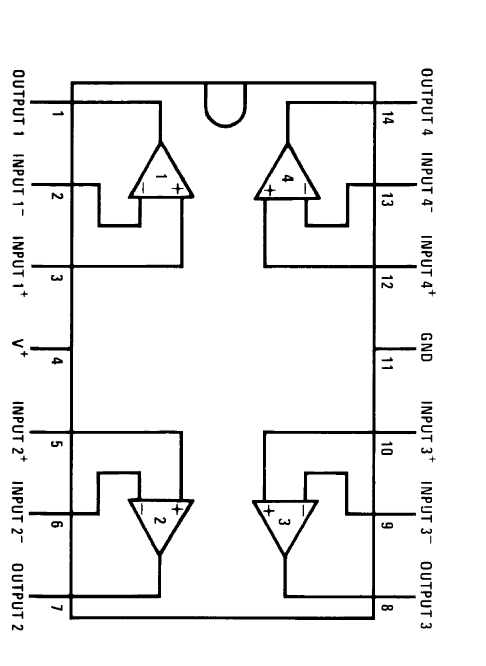
Pin Details of IC LM 324
Parts List for the above mains high, low voltage protector circuit
R1, R2, R3 = 2K2 = 3
P1and P2 = 10K preset = 2
C1 = 220uF/25V = 1
All diodes are = 1N4007 = 8
T1 = BC557 = 1
Relay = 12 V, 400Ohms, SPDT =1
op amps = 2 opamps from IC LM 324 = 1
Zeners = 4.7 volts, 400mW =1
Transformer = 12V, 500mA =1
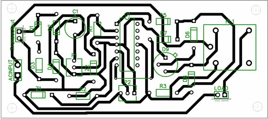
PCB Layout
So far I have explained an IC version of the circuit, now let's see how a mains 220V or 120V operated over voltage and under voltage protection circuit can be built using just a couple of transistors.
A very simple circuit presented when installed in the house electrical may help in restricting the issue to a great extent.
Here I have explained two designs of over and under voltage circuits, the first based on transistors and the other one using an opamp.
3) Over/Under Voltage Cut Off Circuit Using Transistors
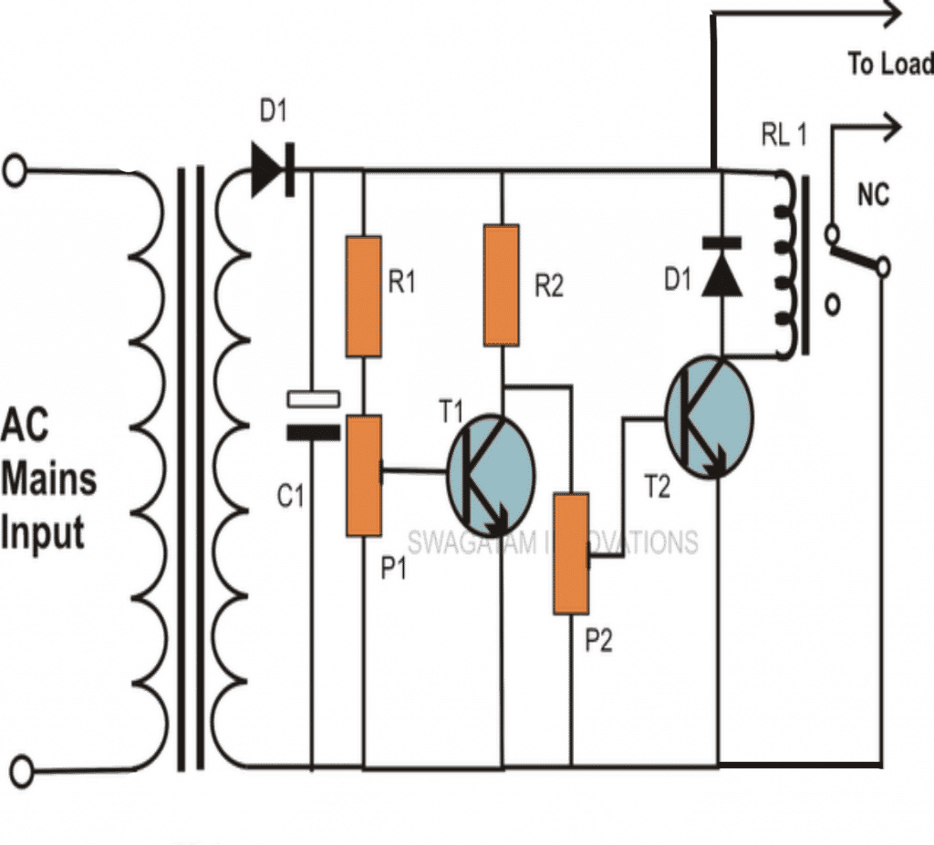
You will be surprised to know that a nice little circuit for the said protections can be built using just a couple of transistors and a few other passive components.
Looking at the figure we can see a very simple arrangement where T1 and T2 are fixed as an inverter configuration, meaning T2 responds oppositely to T1. Please refer to the circuit diagram.
In simple words when T1 conducts, T2 switches OFF and vice versa. The sensing voltage which is derived from the DC supply voltage itself is fed to the base of T1 via preset P1.
The preset is used so that the tripping thresholds can be determined precisely and the circuit understands when to execute the control actions.
How to Set the Preset for Automatic Cut off
P1 is set for detecting high voltage limits. Initially when the voltage is within the safe window, T1 remains switched OFF and this allows the required biasing voltage to pass through P2 and reach T2, keeping it switched ON.
Therefore the relay is also kept activated and the connected load receives the required AC voltage.
However in case suppose, the mains voltage exceeds the safe limit, the sensing sample voltage at the base of T1 also rises above the set threshold, T1 immediately conducts and grounds the base of T2. This results in switching OFF of T2 and also the relay and the corresponding load.
The system thus restricts the dangerous voltage from reaching the load and safeguards it as expected from it.
Now suppose the mains voltage goes too low, T1 is already switched OFF and at this situation T2 also stops conducting due to the settings of P2, which is set so that T2 stops conducting when the Mains input goes below a certain unsafe level.
Thus the relay is once again tripped OFF, cutting of power to the load and prompting the required safety measures.
Though the circuit is reasonably accurate, the window threshold is too wide, meaning the circuit triggers only for voltage levels above 260V and below 200V, or above 130V and below 100 V for 120 V normal supply inputs.
Therefore, the circuit may not be very useful for folks who might be looking for absolutely accurate tripping points and controls which can be optimized as per ones personal preference.
To make this possible a couple of opamps may be required to be included instead of transistors.
Parts List for the above AC mains over voltage, under voltage protection circuit.
- R1, R2 = 1K = 2
- P1, P2 = 10K =2
- T1, T2 = BC547B =2
- C1 = 220uF/25V = 1
- RELAY = 12V, 400 OHMS, SPDT = 1
- D1 = 1N4007 = 1
- TR1 = 0-12V, 500mA = 1


Questions & Answers
hi,swagatam
i have made another ckt for this but that is not accurate.is the 2nd ckt can operate accurately within a range of 20v variation.
hi,swagatam
i have made another ckt for this but that is not accurate.is the 2nd ckt can operate accurately within a range of 20v variation.
Hi Rashmi,
Both the circuits are very accurate but the second one is much easier to build.
hi
i am trying to construct your second circuit. May i know where do u connect the round? it seems it connect to AC main?
Hi, yes the ground connects with one of the mains inputs, the entire circuit then floats with dangerous mains AC, so be cautioned while testing it.
Will you please explain the pin configurations also? I am a beginner.
I am a beginner, please specify the full IC details, PIN configurations and connections. Thanking u!
Please check out the datasheet of the IC LM324 online, you'll be able to compare the pinouts with the above diagram.
Please provide complete and elaborate technical information about your requirement, I'll try to design it for you.
hitman2008@live.in
Put 3 or 4 10uF/250V capacitors in parallel right across the coil of the relay, this will restrict the buzzing of the relay and will simply not allow the relay to activate below a certain minimum level.
what is your relay coil operating voltage?….use capacitors with voltage rating twice of that.
a relay coil will always respond to DC and not AC, yet I will suggest that you first measure the voltage across the relay coil using a good quality multimeter, and then procure the matching capacitor as specified earlier by me.
according to me to activate an electromagnet so that it pulls an iron shaft we would need a DC. so I assume the AC being converted to DC inside the relay
You can connect a bridge rectifier externally and supply the relay coil through this bridge rectifier and then use many 10uF/250V caps across the relay coil, this would make sense.
yes it may be done in that way also.
sir the first circuit
Highly Accurate, Mains High and Low Voltage Cut OFF Circuit, Using IC 324 Explained can i replace 4n35 optp in place of MCT 2E,opto coupler,so this circuit also need to be sets by variable power supply? sir i have a 12 transformer 2000mA can i use it to power the circuit? thank you .
bianzz, you can use MCT2E, however the last circuit is much simpler and sensible so you could try the last one.
a variable PS is a must for setting up the circuits.
if your relay is 12v, then you can use a 12v trafo for powering the circuit
Sir, can you please explain this more clearly = i.imgur.com/ejlMplj.jpg
Moreover in your new diagram, where I have to wire relay to get DC power?
Thanks in advance 🙂
Unknown, your questions suggest that you are very new in the field and in that case the above circuits are not recommended for you, anyway here are the answers:
(+) of the IC will go to the positive of the bridge rectifier.
the load is supposed to be a 220V load that's why it's connected across the mains via the triac.
the left side TR1 stands for trafo, while the right side TR1 indicates the triac, these are accidentally taken identically
R5 is connected to the gate of the triac TR1.
Sir, yes I'm quite new to this field and will be more careful to apply this diagram.
1) Can you please tell me why should I add preset instead of 10k resistor?
2) Where should I wire 12v DC relay?
3) If I want to add 2 second delay timer by 555 IC how can I do that?
1) presets are used for setting the cut-off thresholds by adjusting them appropriately.
2) triac and R5 can be removed and R4 replaced with a relay (with bocking diode)
3) for switching delays add a 220uF/25V capacitor across transistor base and positive.
And 3 i want delay 20to 25 second delay then which value of capacitor I can use and which one transistor I can join
20 to 25 seconds cannot be possible. You can get 5 seconds delay by putting a 1000uF/25V capacitor parallel to R4. And make sure R4 value is a little high around 47K
Sir, please let me know if this OK = i.imgur.com/oWIZzrK.jpg
a) I have removed 220v AC line across PCB.
b) Wired (+) of the IC to the positive of the bridge rectifier.
c) Added 12v DC relay as per your instruction.
If anything goes wrong it will be helpful if you correct this diagram for me 🙂
yes everything's correct.
sir i have finish build the lats circuit tell me how to set it sir can this lats circuit be use for refrigerator?
sir can you please help me set the last circuit how do i set to?
feed the lower threshold AC to the trafo and adjust P1 to just switch OFF the triac.
Next feed the higher threshold voltage to the trafo and adjust P2 to just again switch OFF the triac.
the triac will remain switched ON only in between the above high/low thresholds,
your circuit is set now.
you will need a variac for doing this.
ok sir please can i use this circuit
How to Make a Simple 220V Transformerless Power Supply Circuit Using a Single MJE13005 Transistor to set this last circuit?
yes, can be used, but be careful as the circuit is not isolated from mains and could give lethal shocks if touched with naked hands.
ok sir thank you for the respond,sir there's something confused me a bit how will i know if the triac is off? sir how can one voltage supply circuit be use at the same time to feed low and high voltage to the transf? or should i connect the supply out put to the rectified and adjust the supply variable to high and low ?can you please provide me what current the triac need before it can switch off? thank you.
you can put a LED in series with the triac gate for the indications.
yes you can use a variable power supply for quickly varying the supply high to low and oppositely for confirming the results.
the opamps will take care of the triac switching as per the settings.
sir im asking can i use 12v batt to set high out put and extra 6v batt for low out put?
tell me the mains AC threshold cut-off levels that you desire, i'll give you the equivalent DC values for setting
if it reach 250v AC and low110v
please also measure and provide the DC voltage supplied to the circuit at normal 220v….this will be required for the calcualtions
can it as a surge protector?
no
SETTING UP THE PRESET
The relay will remain deactivated only as long as the input DC is within the window limit between 11.50 V and 14. 90 V, which corresponds to the normal AC level between 200 V and 260 V. Beyond these limits, the relay will get activated causing the relay and the load to switch OFF.
I am confused does it mean that the output from the relay to load is taken from COM and N/C contacts of the relay since at normal AC inputs between 200v and 260v the relay remains deactivated according to the procedure you gave us. Please I need clarification.
There was a slight mistake in the explanation, I have corrected it now, please check it out.
Yes I have seen it. Thanks
hey budy i wana make Transformerless Stabilizers plz hlep me how can i make it.
sorry, that's not possible.
will be very complicated.
why thats not possible plz tell me any kind of salutation thats importatn plz im try to understand the complication of the circut tell me any diagram any data
the voltage step-up transformers will need to be built using ferrite transformers involving complex switching circuits, just as we have in compact inverters.
tell me about compact inverters sir i will try for switching circuits and i wana use (pic16f72) with lm 324 guide me about that.
presently i don't have enough info regarding it, once i get them will provide it you.
thanx sir
Hi Swagtam,
Can you send me circuit diagrams of both the above circuits on my email add. as my browser not loadingthe circuit diagrams. my email add. is instructions555@gmail.com
Thanks & Regards,
Hi SW, refresh or restart your browser or try some other browser it will surely load, or there may be some problem with your internet connection
sir i want to use this circuit https://www.homemade-circuits.com/2011/12/simple-mains-high-and-low-voltage.html as a final year project. i submited the project as electronic wacthdog control system to the supervisor and he is requesting for the abstract, please sir can U assist me with the written materials for the project and what is the difference between this circuit and that of the stabilizer. thanks as i awaite your quick response. my email is canioko@yahoo.com
Anioko, all the data are provided in the article explanation, you can rephrase the details appropriately as per your requirement.
The abstract material can be found at the beginning of the article.
a stabilizer will automatically correct the voltage fluctuations by supplying extra voltage to the appliance or by deducting it as per the mains situation.
The above circuit will not do this rather cut off the mains supply to the appliance if it tends to shoot above or below a certain predetermined danger level
DEAR SIR, PLEASE CAN I USE THE FIRST CIRCUIT FOR A PROJECT WORK. IF YES IS THERE ANY MORE CORRECTIONS THAT ARE TO BE ADDED TO THE CIRCUIT?
Dear Anioko,
The first diagram is correct in all respects, you can use it for your project but it's unnecessarily complex, the lower one will give the same results and is more compact, a relay can also be used instead of triac in the second design.
dear sir recently Ibuilt the above circuit but it does not function the mct 2e even using a transister. please help me at dumbara27@gmail.com
thanks
Dear Nisha, build the second circuit it's much easier, the circuit is a simple comparator based design and there's no way it won't function if you did everything correctly.
Connect an LED in series with R3 in the second diagram and check the response by moving the presets
hi once again,how r u hope fine
i want to use reliable transformerless power supply with auto cut off circuit as u published
https://www.homemade-circuits.com/2011/12/highly-accurate-mains-high-and-low.html
any modifications?and in this page there is also a second ckt which should b used and i am asking for transformerless power supply because the transformers i get are getting hot they will fail after some time and also in high voltages there is maximum chance of burning of transformer and if transformer fails the relay denergize and the connected appliance would burn then the cut off ckt will b safe but the main target the appliance will burn off
so please give me a ckt with a reliable reliable psupply which can bear high voltages, fluctuations ,no zenner shorted and no heating of components which should run continiously for example : i am using to led street lights with day night ckt ,the supply should b always connected if any small problem comes the main lights will surely b in trouble and u know how expensive are these
please dont mind for so long detailed approch thanks and i admire for ur great hobby
which is not only helping the persons like us and also ur providing good knowledge for the society
hats off for u .god bless u
thanks jeelani, I have updated the required diagram in the above article…..
thanks for u r prompt response
Sir I want a circuit for under voltage & high voltage mait cut for ac motor using for water pump.show me the direction please..govind
govind, you can try the second last circuit above with the following modifications:
remove the triac and R5, and replace R4 with a relay…
hi,i think rectifier is missing
Hi Sir,
In the above first circuit (Highly accurate over/under voltage CKT.)
can u pls tell me connections of OPTO coupler,
Pin 1 = anode (connected in CKT)
pin 2 = cathode (connected in CKT)
pin 3 = NC
pin 4 = Emitter (connected in CKT)
Pin 5 = collector (connected in CKT)
then where to connect pin 6 = Base of OPTO…..?
and Bc547 given in the components list, are not needed in the circuit. Right….?
Thanks in Advance…..:)
That's correct Vamsi,
the base of the opto transistor is unused, so it can kept open.
BC547 are not used since the opto transistor itself are used as relay drivers.
Hi SWAGATAM…
Here OPTO's output is too low to energise the 12v relays. can u pls explain the solution… Thanks
Hi Vamsi, you can refer to the following article for solving the issue:
https://www.homemade-circuits.com/2013/02/how-to-drive-relay-through-opto-coupler.html
Thank you sir….:)
Hello yonder,
I found all your circuit and projects interesting but please I need a special assistance. I want to build a Low and high battery full cutoff that can handle about 360VDC (30 Batteries in series) such that when battery is full at 405VDC charging Voltage will cutoff and when battery drop to like 325VDC it also cutoff battery low.
Please, do share this experience with me.
Hello yonder, I'll try to design it and post it soon…it might take sometime, please bear with me until then
R1, R2, R3, R4, R5, R6, R7, R8 = 4K7, What is 4K7
4k7 is 4.7 k resistor
Hello Sir,
I want to build a system that cuts off the supply for lower level at 150V and higher value at 370V AC. I don’t have a clarity on what the DC Voltage corresponding to this will be.
Hello SST, you can find the equivalent values through simple cross multiplications, just check your input AC and the equivalent DC from the bridge rectifier of your power supply.
Comparing them you can find other equivalent values, as shown in the following example:
Suppose you find 12.8V DC at 230V AC input, other values could be found by solving the following expression:
12.8/y = 230/z
Here “y” will be the required unknown DC value, and “z” will be the intended AC low or high cut off value
Thank You sir for your help.
Hi Sir,
This question is a little bit of topic, apologies. Will it be possible to design a booster circuit to boost 24V DC to 240V DC. I designed a booster circuit, but I am unsure if it will be practical and compact.
Hi SST, yes it is possible….you can try the IC 555 boost flyback circuit concept explained in the following article, and see if it works or not
https://www.homemade-circuits.com/generating-electricity-from-road-speed/
Hi Sir,
I want to design a circuit such that it should cut off the input supply voltage if input voltage is below 150v or above 370v. Sir, can u please design the above circuit for this specification?
Hi RSG, first find out the equivalent DC value of your power supply with respect to the input AC level…. I am referring to the power supply that you would be using for powering the above circuits.
Let me know this then I’ll tell you how to proceed further.
Hi sir,
My DC voltage corresponding to 150V is 75V and corresponding to 370V is 185V.
Hi RSG, I meant the DC voltage that you would be using to operate the circuit and the IC. 75V and 185V cannot be used for operating the circuit, it has to be in the range of 12V
Hi Sir,
I would like to design a circuit for high and low voltage cut off. Suppose if the input is as high as 400V and on the lower side 160V, can I use this circuit? will transformers be available to step it down to a low level.
Hi gks,
yes you can use this circuit for any desired cut off thresholds. But this will not stabilize the output instead will only cut off the mans supply at the specified levels. If you are referring to the input transformer, it will need to be specially made to order for withstanding 400V input, or you can opt for the capacitive version and employ a 600V capacitor for achieving the same.
Sir,
If I am using a voltage divider in place of that preset, I can get voltage levels at 6V. Will that be adequate enough? ( a 10K series resistor with 420 ohm in series, and taking the output across 420 ohm will give 6V)
gks, That may be possible but only after setting-up the opamps practically by feeding 160V and 400V and adjusting the presets appropriately for getting the required cut offs on these voltage levels..
Once this is achieved you can measure the adjusted values of the preset and replace them with fixed equivalent resistors.
Sir,
What is the name of the triac.
You can use BTB08/600BW
Hi sir
can you sent me detailed circuit for transformer less mains high low voltage cut off circuit
Hi Prasanth, the second last circuit in the above article shows the transformerless version. You can implement it with appropriate setting up procedures.
Hi Sir,
I am currently trying to implement this circuit to cut off the voltage for below 150V and 370V. My step down transformer produces an output of 75V and 175V. I used a voltage divider circuit in order to provide an input of 12V to the IC and also made changes to the zener diode circuit. But the entire voltage is appearing across the triac for voltage as low as 1V.
Hi SST, your step down transformer is supposed to produce 12V DC in response to a 220V input AC, how can it produce 75V?
And if you are using a transformer for powering your circuit, it is supposed to be a a 0-12V/220V transformer. Make sure you are doing the procedures with proper understanding.
I used a 440V/ 220V transformer which belongs to another part of my circuit that I am currently working on. This part works fine, so I can’t change the transformer at that part. in order for cut off I used a voltage divider circuit such that it would produce 12V.
you can follow the same proceduers as explained above.
Just forgot to tell you:
Make sure the positive pin Vdd of the opamp gets a 12V fixed supply from a 7812 IC.
And remember the whole set up is not isolated from mains AC and can be extremely lethal to a human touch
Hi Sir,
If I am opting for the transformerless version, what all changes would I have to make in order to cut off the circuit at 150V and 370V AC.
Hi SST, you can build the second last design as shown in the diagram. Make sure to connect LEDs between A1 output and ground, and A2 output and ground…both the LEDs should have its own 1K series resistors.
initially keep the preset to ground level…then feed 370V and adjust the upper preset until the A1 LED just lights up
Next, feed 150V at the input, adjust the lower preset until the A2 LED just lights up..that’s all the set up is complete.
The 100K resistor should be rated at 3 watts, and the 105 capacitor should be rated at 600V
Make sure the positive pin Vdd of the opamp gets a 12V fixed supply from a 7812 IC.
Sir, I am getting output acroos my Triac for any voltage below 150 and nothing across the load. (is this normal). I just wanted to check if there was any voltage across the loads for a lower voltage.
SST, first you must follow the setting up procedure that I explained, and make sure the triac is responding correctly to the opamp switching, at the moment I am unable to understand what exactly you have done and how you are testing it?
Hi Sir,
I configured the lower opamp circuit, and it is working for 150V, but when the output is reduced below 150V it takes some time for the LED to completely go out.
SST, are you using any filter capacitor across the DC supply line, it could be due to the slow discharge of the capacitor
Hi,
Can you please explain where the connection goes after R8. Why does it go to the output of A1 . Doesnt it short. Should it go to the ground? Also R1 to R8 is mentioned as 4K7 resistors. CAn you be morespecific please like is it 47K and at what wattage?
Thank you
Hi, yes please connect R8 end to ground and not to A1 output, otherwise the upper opto and the LED will not operate when A4 is high.
4k7 = 4.7K
Thanks Swag.. That makes sense.
Sir which components list should i refer for building transformerless triac circuit
Razi, I have updated a new diagram with all the part numbers in it. Please check it.
Thank you very much swag.
You are welcome Razi!
Really appreciate your sincerity
Hi,
If I want to use bridge instead of D1-D4 then how to attach C1 capacitor?
In which diagram?
In majority of diagram mentioned on this page. but for your reference very first diagram. in which C1 is attached between diode from D1 and D4.
You mean to say if you “don’t” want a bridge? Then you can use a single diode, and put a capacitor across the cathode and ground
I any situation a filter capacitor is connected across the positive and negative line of a circuit, it can be anywhere across the +/- line.
hi, swagatam,
please clear about pin number or connection of triac bt139 because it confuses if i see graphical symbol available for data sheet of bt 139 with your illustration.
2nd in transformer less illustration you have mentioned lm 358 and this opamp have 8 pins, but in illustration you have also mark pin# 4 and 11 and it seems that it is lm 324. Please clear that which one might be used for transformer less type circuit?
Hi Umar,
I have updated a new diagram with all the details please check it now!
You can use both LN324 or LM358, but I have shown LM358 in the diagram
hi, Swagatam,
I have made schematic in Multisim and simulate it, but it cannot simulate as I intend. May be I connect something wrong. Tell me how I can share it to you so that you can check it.
Hi Umar, I won’t be able to help simulation results, I can only help with practical set up, and I can guarantee that it will work 100% OK
Hi,
I am little bit confuse. Can you please mention LM358 pin number with connection? And thanks that you have mentioned its 4 and 8 pin also BT139 connection after I have asked about that.
And can you please tell me that which software you use for schematic so that it is easy for me to identify pin number. For instance if I add LM358 in multisim, it’s A1 and A2 shows “+” & “-” in “+” up and “-” down sequence but you schematic shows “+” up “-” down for A1 and for A2 “-” up and “+” down. I have also use proteus for schematic and it also identify as same as Multisim.
Hi,
you can see the following diagram:
https://www.homemade-circuits.com/wp-content/uploads/2019/06/LM358-internal-layout.png
You can use any opamp anywhere since both are exactly identical. I use CorelDraw software
Hi, swagathan.
i have one doubt !
can i made the time delay by using op amp like as how to took stabilizer to send output for any appliance..
Hi Parveez, I did not correctly understand you question, where exactly do you want to add the delay feature in the stabilizer circuit
hi
can i use pc817 optocoupler instead MCT 2E
THANKS
yes you can….
Hi, Swagatam
I want to extrapolate the circuit by adding an alarm system that will buzz when the voltage goes back to normal. Now can i do that with of the above designs?
Hi Kgosto, you can add a DC buzzer with a capacitor in series. Whenever power returns the buzzer will buzz for a short period until the capacitor charges and then shut off
Sir exactly where join in series in circute , buzzer and capacitor
And can I use buzzer in tranformar less circuit
Dilip, you can join a DC 12V piezo buzzer parallel to the R3 resistor. Positive wire will go the op amp side, and the negative wire will go to the ground line. The connection will be the same for the transformerless version also.
Hi swagathan.
I am parveez.
i had dropped one question regarding the delay in stabilizers !.
Instant i had received your replay thanks for that…
Question is ! would i use lm324 op amp ic to create initial delay for switching like lnput voltage to output voltage through relay…?
Ex: stabilizer device ! if i put on the power button of stabilizers from the main supply this stabilizers unit take 30 sec to 1 minute to supply his own power to other device !.
stabilizer Instant doesnt allow actively pass the power to other device! It should take time to allow the power to other device once we could put on main supply.
Can we create initial delay for starting by using LM324.?
please if it is yes share little bit circuit explaination
Hi Parveez, you can make it using two transistors and a relay….is there any specific reason for using LM324??
Thank you
Swagathan sir,
there is no any specific of 324… i made the delay by using transistor and also used 324 for implementing high cutt off and low off.
I am thinking i could do all operation by using same ic.
you have cleared my querries..
thanks for clarifications
Thanks Parveez, then a transistor circuit will be a better option.
here’s an example application for you:
https://www.homemade-circuits.com/simple-refrigerator-protector-circuit/
I constructed the circuit above but I want it to have a voltage range with which it will operate. I want a range of 230V to 240V and anything out of that range should be considered a low (240V). Now how should I extend the circuit.
Thank you in advance.
Hi, Do you wish to have only low threshold cut off limit, and no high limit? Please clarify!
I want to have both. What I mean is if the supply voltage is lower than 230V then it should be considered as under-voltage and thus the system should isolate the load. And also if the supply voltage is greater than 240V then that should be considered as over voltage and the load should be isolated.
The above designs are exactly meant to execute the same. There are two presets, one adjusts the lower cut off threshold while the other one fixes the upper cut off threshold
I wish to have low and high threshold. Anything less than 230V should be considered as under-voltage and anything over 240V should be considered as over-voltage and the load should be isolated from both of these cases.
I was looking for a circuit that could protect and save my laptop battery life and found this article which was interesting but I was unable to find what I was looking for. What I want is that, As my laptop’s battery capacity touches 80%, the circuit must switch off the power and automatically switch on as battery charge drops to 20%(This process insures smooth battery life). This idea should have been implemented by laptop vendors because this would ultimately save customers from changing batteries after a month or two. Although some laptop vendors claim to have this integrated already but I personally could not benefit from it and did not see any practical results.
The above circuits are for protecting gadgets against voltage fluctuations, these are not related to battery charging. For protecting battery you can try the following designs:
https://www.homemade-circuits.com/opamp-low-high-battery-charger/
I am unable to understand ,how we set the upper and lower threshold value and how we vary them.
Further how much precisely does it detect the over/ under voltage and what is its tolerance %
I will try to update the info soon in the artcile.
I needed the solution soon as I am using this circuit in my college project
Sir,
How to setup Tranformerless low and high voltage cut off circuit using Trac
Deepak, It is explained under “setting up the presets”
Hi,
I’ve made the circuit using PNP relay driver by using BD140 PNP transistor (available with me). When the comparator O/Ps are low, it is able to switch ON the load. But if the voltage rises/ lowers to the preset value, it isn’t able to switch off the relay. Suppose after a power interruption, a low voltage/ high voltage appears at the input supply, in that case also the relay is able to switch ON. My point of concern is the relay shouldn’t be ON in the High/ Low Voltage range. Also kindly let me understand this point as “However the moment any of the opamp output goes high (which may happen during abnormal voltage conditions) the diode junction also becomes high, restricting T1 from conducting”. But how? The Diode D6 will be in reverse biasing during abnormal (High/ Low) voltage. And until voltage appears at the PNP base terminal, the relay will not be switched off. Kindly help me in this regard.
Hi, If either A1 or A2 output turns high, then the cathode of D6 will become high which will block the T1 emitter current from reaching the ground line via R3, ensuring T1 is switched OFF. T1 can conduct only when D6 is forward biased which can happen only when both the op amp outputs are low.
You can replace the D6 diode with an LED which will give you a clear indication regarding the switching of the transistor T1.
Remember T1 can conduct only when the current from its emitter passes through the base diode diode D6 and through the resistor R3. If D6 is reversed biased then this current cannot flow, and T1 will be switched off.
Also, try increasing the value of R3 to 10K and connect a 4k7 across base/emitter of T1…. this will further ensure that T1 switches OFF when A1, or A2 outputs are high.
I want a circuit with lower limit cut off Ac 90 v and upper limit cut off Ac 120 v available AC 110 V can u design for me
You can use the same concept that are presented in the above article, by adjusting the presets accordingly.
I stumbled on this article while looking for an off-the-shelf low-voltage AC cut-off. I have two household loads hard-wired to a dimmer and would like one of the loads to shut off at a specific voltage, but have the other stay on (I need to test more, but around 60V-AC). I picture the end result to be dimmer that is hard wired directly to both loads, but the load that needs to turn off would have this similar circuit hard-wired inline.
This kind of circuit design/construction is way out of my wheelhouse, but I do have basic electrical knowledge and can solder… I don’t mind taking the time to figure things out, but this is a bit over my head. Before I dig in, I’m hoping you can at least verify if this circuit is a reasonable way to solve my issue if I take the time to figure out how to change the low voltage cut-off. Also, I have limited space (about the size of a single electrical box), so hoping to make the smallest circuit possible. Since I don’t need the high voltage cut-off, would the circuit be appreciably smaller and/or simpler if that feature was removed?.
I am afraid basic electrical knowledge will not do for this design. If you are not an electronic circuits expert then making this circuit successfully can be almost impossible for you. The circuit will consists of an opamp with presets and a lot of adjustments. Setting it up can be a big headache if you are not well versed with electronic circuits and op amps.
Thanks, better to know that ahead of time. Any recommendations on the best way to find someone to hire who would do a project like this as a one-off, or is that not really a thing…. Thanks again.
You are most welcome! You can probably find many good electronic engineers online for hire through sites like freelancer . com, upwork . com etc
Good day sir. From the circuit using lm358; what is function of 1N4148 connected to the base of bc557 and i don’t understand the way its cathode and anode is being connected. Won’t it block the base of bc557 from getting negative signal from the output of the opamp?. Also what is the function of the 1micro farad/25v. Does it function as time delay?
Thanks sir. I now understand. I want to incorporate the circuit to my contactor-based automatic 3-phase selector that I constructed, so that if there is over/under voltage in any of the phases or the selected phase, the triac will disconnect the ANLY TIMERs pin 2 which is connected to the coil of the contactor, to de-energize the contactor
No Problem Emmanuel, you can go ahead with it, but remember to adjust the presets correctly otherwise the circuit can malfunction.
Dear sir.
Please sir, out of the 3 tested 220V high and low voltage cut off circuits, which one has the narrowest window threshold?
Such that I can set it to operate on the following conditions:
1. To cut off the supply to the load when the voltage reaching the load is above 220v , say 230v from 220v mains supply.
I. e cutting off at exact 230Vac
2. To cut off the supply to the load when the voltage reaching the load is below 200V, say 190V from the 220v mains supply. I.e cutting off at exact 190Vac
Hi Godfrey,
You can make the window wider or narrower by setting the two presets appropriately.
You can set the high voltage cut off by suitably adjusting the P1 preset, and the low voltage cut off using P2 preset.
However, the cut off cannot be perfectly accurate, if you set it for 230V then the cut off may happen at 228V or 232V sometimes
Okay sir,
Thank you so much.
Please sir, are you referring to the first circuit( transformer based) or the second circuit (transformerless/triac version)?
Thank you
All the op amp based circuits are identical, and have identical setting up procedures.
Good day sir! I know you hardly have chance these days to post new projects. There is this commercially available product called tv/ fridge guard which has OFF, WAIT and ON LEDs indicating the state of mains voltage. I know that WAIT is delaying period and ON is when the relay is latched and power is supplies to the load but the period of OFF is what I don’t understand. Please can you suggest a circuit diagram for that tv guard with such qualities having the appropriate position where the LEDs can the placed to demonstrate OFF, WAIT and ON.
Hi Mosses,
I have posted plenty of new circuits in this blog, you can check them under the “New Projects” link.
What is the function of the unit, is it a delay ON timer circuit? Or a stabilizer?
The OFF LED is confusing, because if there is no mains power how can the OFF LED get the supply to switch ON?
Presently I do not have any such design in this blog, except a fridge protector delay ON timer circuit, but without any LEDs.
https://www.homemade-circuits.com/simple-refrigerator-protector-circuit/
Dear sir,
Please sir, I don’t really get the outcome for the settings of P1 to P4 in the first circuit with indicators.
1. Please sir, what will be the low cut off voltage and high cut off voltage as per the values you have used to illustrate?
2. From second circuit (i.e transformerless version)
Concerning setting up the presets P1 and P2 from point 5 down in the article.
Please sir, how do I know when the OpAmp is High and when it’s Low while adjusting the presets?
Thank you very much sir
Hello Godfrey,
First you will have to connect a low equivalent DC supply with the op amps that corresponds to 230V, for adjusting the high voltage switch ON, and then connect a low equivalent DC supply that corresponds to 190V for adjusting the lower threshold switch ON.
I have explained the procedures under “Calculating the Cut-off Thresholds” and “Setting up the Presets”
Hello I’m mark MUSYOKA kindly sent for a circuit of voltage cut off delay alarm
Hi Engr Sir.
I’m Kings Jerry.
Thank you sir for this clear and well explained diagram.
But pls sir according to the diagram, the rated step down transformer is 12v. but while setting using variable power supply, the setting of the op amp was both 12v ,14.5v, and 15.5v, while the rated transformer to carry the circuit is 12 volts .
so pls Sir throw small light regarding this sir.
Hi Kings,
The 12V after rectification can become as high as 16V. So what you are seeing is correct, the 12V transformer after rectification will produce outputs higher than 15 V.
Very nice post. Thank you for sharing your design. I’m retired in the Philippines where stable power is but a dream. Our emergency generator logged 237 outages totaling 333 hours in 2022.
Because at least a couple of those outages included “brown-outs” where voltage dropped down to around 130-150 VAC in a quick repetitive fashion (should be between 220-240) I added a time-delayed contactor to our house circuit so that every outage will be at least 30 seconds long, giving the generator time to spool up and saving our appliances from damaging repetitive power surges which are hell on the motors. But it doesn’t trigger reliably on low-voltage events so I’m going to apply your circuit to the application.
Because parts are a pain to locate over here, I’m hoping I can find a pre-built solution. But in the worst case I have your circuit in my back pocket if it comes to that.
Thank you again for sharing.
Thank you for your feedback, appreciate it!
I was going through your Mains AC Home Protector Circuit. It is amazing. I was also going through your 3 Tested 220V High and Low Voltage Cut OFF Circuits Using IC LM324 and Transistors, wherein I was fascinated by the transformerless mains high low voltage cut off circuit version in the section Using Two Op amps Only.
I must accept my weakness for transformerless circuits with triacs b’cos of their compactness and efficiency. I think risks can be avoided in such scenario using fuses. Thus the almost same query that I have posted in your other page. Can Mains AC Home Protector Circuit be amalgamated with transformerless mains high low voltage cut off circuit version in the section Using Two Op amps Only with suitable modifications to enjoy all the features of both, i.e. high low voltage cut off with surge protector without using transformer and relays.
Yes, i think that’s possible, I will try to update the design in my home protector circuit article soon.
I need pcb layout of first circuit.
Sorry, I do not have the PCB layout, you may have to contact a PCB designer for this…
I successfully made the pcb layout of first circuit.
That’s great Ritesh, all the best to you.
Hi Mr. Swagatam, i have recently made one of your circuit, the one which is a transformer based. I noticed that when the applied ac voltage is below 100 ac volt the relay is not activated may be because the power coming out of the transformer is not enough to power up the relay. Upon seeing your transformer less design i was fascinated by it. I’m not an electronic but i love doing electronic stuff. I’m wondering how to put an LED indicaror. Can I just put an LED on the base of the pnp transistor and on the out put of the comparators. Thanks in advance.
Thank you Alinader,
Yes the relay may not be activating due to low voltage, in that case you can try using a 5V relay.
The transformerless alternative is also very good, since it is a solid state version and more reliable, although is very dangerous to touch in powered condition.
You can attach a series LED with the base of the PNP for getting the ON/OFF indications of the load.
You may also find the following design intresting:
https://www.homemade-circuits.com/mains-ac-home-protector-circuit/
Thanks a lot sir, the one you recommended is the one i exactly replicated. I also modified it by removing the low voltage feature using only one of its op amp to detect only the high voltage and still whenever the input ac voltage is below 100 volt the relay is not triggering and the green LED is barely lit. Your recommendation to use 5 volt relay is the answer, i have actually tried replacing my 1 ampere 12 volt transformer to 200 milliampere transformer and it made a difference and it operates now on a little bit lower voltages i think at 100 ac volt. This made me think if i instead use a 6 volt transformer and a 5 volt relay. But the transformer less version is still the best, because very small power is needed to trigger the triac. I hope in the near future you can modify it to include the LED indicators. I was wondering if i should remove the d6 on base of PNP transistor or just insert the LED in series with that d6 diode. Thanks once again, i wish you good health and more project to come.
You are welcome Alinader,
Using 6V transformer and 5V relay would give you the same results, the relay might fail to operate at lower AC levels.
Instead, you can use a 12V transformer (200mA) and supply the 5V relay through a 7805 IC.
Yes, the transformerless version is the best but since it is not isolated from mains AC, it is dangerous to touch in the open and powered condition.
You can remove D6, or keep it as is and wire the LED in series with D6, both will work.
Do you have any tested and assembled low and high voltage cut off boards working in 6 volts and three phase low voltage and high voltage cut off
The above circuits are all tested. However, I do not yet have a 3 phase version of the above designs..
Hello,
I need to cut 120v AC through to a battery charger based upon the battery state of charge. Specifically, when the voltage from the battery drops to 13.2 volts DC, AC cuts through. Once battery voltage reaches 14.6, AC is cut off. I’m assuming the AC cutting through and off is via a physical relay, so just need to control that make break. Sounds simple, but thought I’d run it through an expert for opinion.
Thank you,
MK Black
Hi, if you want the cut-off to happen on the 120V side, then I would recommend using a triac based circuit as explained below. However it will not initiate when the battery drops below 13V, in that case you may have to use a DC side cut off arrangement…
https://www.homemade-circuits.com/battery-charger-circuit-using-triac/
pls I am building a batteryless inverter from a pv power input voltage from 90vdc to 400vdc to power the inverter but I don’t know how to put a low voltage cutoff on pv input so that it will protect my inverter and my load when their is low voltage on pv then the inverter will tripe off. pls help me with the circuit diagram well explain
Please do not use the above diagram, it was rated for 90V, but your maximum voltage is 400V, so the diagram must be redesigned…I will do it soon and post it here for you soon..
OK, here’s the circuit which you can use:
https://www.homemade-circuits.com/wp-content/uploads/2026/07/90-to-400V-low-battery-cut-off-circuit.jpg
Sorry, there’s no 12V relay which can handle 400V safely, so it seems the above diagram might not work…so the ultimate quick solution to cut off inverter at 90V low voltage for a 400V panel, is the following MOSFET version:
https://www.homemade-circuits.com/wp-content/uploads/2026/07/90-to-400V-low-battery-cut-off-circuit-for-PV.jpg