In this article I will elucidate a simple universal H-bridge module using BJTs and N-channel MOSFETs.
This module can be integrated with any standard oscillator ICs such as IC 4047 or IC SG3525 or even IC 555, to create a highly efficient H-bridge inverter circuits.
Why using 4 N-channel MOSFET H-Bridge is the Most Efficient
Using 4 N--channel MOSFETs in an H-bridge configuration is considered to be the most efficient topology because N-channel MOSFETs have much lower RDSon compared to their P-channel counterparts.
Lower RDSon means lower drain to source resistance, which ensures lower heat dissipation and higher current transfer across the MOSFETs.
The Challenge behind 4 N-Channel MOSFET H-Bridge
However creating a H-bridge using N-channel MOSFETs can be difficult since it involves a relatively complex a bootstrapping network.
The bootstrapping network refers to a small circuit network around the gates of the high-side MOSFETs which enables the high-side MOSFETs to conduct freely by ensuring that its gate voltage is always around 12V higher than its instantaneous source voltage.
Now, let's try to understand how our universal H-bridge circuit module using N-channel MOSFETs works.
How the Circuit Works
If you don't want to read the following description, you can watch this video instead:
Referring to the diagram below, let's assume an instantaneous moment where the left side oscillator input is low, and the right side oscillator input is high.
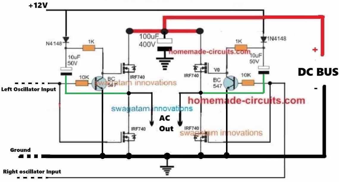
In this situation, the left side BC547 is turned OFF due to the absence of the base switching voltage, and the left side 10uF/50V capacitor is charged up to the battery voltage level through the 1N4148 diode.
Now, the left high-side MOSFET gets its voltage through the 1N4148 diode, and the 1k resistor, and makes an attempt to conduct.
However, as soon as the MOSFET drain voltage reaches its source terminal and exceeds its gate voltage (12V), the conduction stalls, because as we know, ideally, for any MOSFET to conduct, its gate potential must be around 10V higher than its source potential.
This is where our BC547 and 10uF bootstrapping network comes into action.
When the Left high-side MOSFET drain voltage reaches the source terminal, this voltage is forced into the 10uF capacitor through its negative terminal.
This source voltage entering the negative terminal of the 10uF capacitor now comes in series with the existing 12V stored inside the 10uF capacitor.
So, as the source voltage rises it pushes the stored potential inside the 10uF higher so that the total voltage at the gate of the MOSFET is always 12V higher than the source voltage of the MOSFET.
So, when the source voltage is 12V, it adds up with the internal 12V of the 10uF capacitor producing 12 + 12V = 24V at the gate of the high side MOOSFET.
This means the effective gate voltage is now the difference between the total gate voltage and the source voltage, that is 24V minus 12V = 12V, or if suppose the drain supply is 100 volts, then the effective gate voltage will be 100 volts plus 12 volts minus 100 volts = 12 Volts
This ensures that the gate voltage of the high side MOSFET is always held at 12V higher than its source voltage.
This in turn enable the high side N channel MOSFETs to conduct freely and efficiently, regardless of the applied drain voltage level. This may not be possible if P-channel MOSFETs are used, although P-channel MOSFET wouldn't require a bootstrapping.
A High-side P-channel MOSFET might not require a bootstrapping, but the main disadvantage of using P-channel high-side MOSFETs is, its drain voltage cannot exceed the gate voltage, which simply means that if the oscillator IC output is 12V, then the load voltage cannot exceed 12V, which appears to be a big drawback, which is completely eliminated if N-channel MOSFETs are used.
That's it! this concludes our tutorial on a simple H-bridge circuit module using N-channel MOSFETs which can be used to transform any center tapped inverter into an H-bridge inverter.
I hope you liked the tutorial…. for any further doubts or queries, please feel free to comment below for quick replies.
Summary
The H-bridge inverter topology is the most efficient one, since it does not necessitate the use of center tap transformers, and allows the use of transformers with two wires. The results become even better when four N-channel mosfets are involved.
With a two wire transformer connected to an H-bridge means the associated winding is allowed to go through the push pull oscillations in a reverse forward manner. This provides better efficiency as the attainable current gain here becomes higher than the ordinary center tap type topologies.
However better things are never easy to get or implement. When identical type mosfets are involved in an H-bridge network, driving them efficiently becomes a big problem. It is primarily due to the following facts:
As we know an H-bridge topology incorporates four mosfets for the specified operations. With all four of them being N-channel types, driving the upper mosfets or the high side mosfets becomes an issue.
This is because during conduction the upper mosfets experience almost the same level of potential at their source terminal as the supply voltage, due to the presence of the load resistance at the source terminal.
That means the upper mosfets come across similar voltage levels at their gate and source while operating.
Since as per the specs, the source voltage must be close to the ground potential for efficient conduction, the situation instantly inhibits the particular mosfet from conducting, and the entire circuit stalls.
In order to switch the upper mosfets efficiently they must be applied with a gate voltage at least 6V higher than the available supply voltage.
Meaning if the supply voltage is 12V, we would require at least 18-20V at the gate of the high side mosfets.



Questions & Answers
can this be used to drive output MOSFETs in class d amplifier
Yes, it can be used to drive output MOSFETs in class d amplifier.
Hello, what is the maximum frequency of this H-bridge if i use a it with a TL494?
Thank you
The BC547 can handle upto 300MHz, so it can be easily used with TL494 IC.
Hello, I want to ask, I want to make a cascaded H bridge inverter using 8 IRFZ44N MOSFETs to create 5 voltage levels, I use the IR2110 driver IC to control it, do you have any suggestions regarding this?
That looks like a great project choice.
First remember that because this is a cascaded setup, you absolutely must use two completely isolated DC power supplies for the two individual H-bridges. If you try to share a single DC source between them you will end up creating a direct short circuit.
Second, the IR2110 relies on a bootstrap network for the high-side gate drive. Because of this you cannot run your PWM at a 100 percent duty cycle. The high-side capacitor requires the low-side MOSFET to switch on periodically so it can recharge.
3rd, make sure to handle your dead-time carefully. The IR2110 does not have internal dead-time generation so you will need to program a small delay of about 1 to 2 microseconds directly into your microcontroller code to prevent shoot-through.
Lastly… keep an eye on your voltage margins. The IRFZ44N is rated for 55V so it is best to keep your individual DC bus voltages around 12V to 24V max to give yourself a safe buffer against inductive voltage spikes. It is also a clever move to use optocouplers to isolate your control logic from the drivers. Good luck with the build, let me know how it goes.
thank you sir for your reply,
sir can I connect both 12v supply for bc547 and dc bus supply eachother
means can I use only one same dc positive supply to all circuit
thank in advance sir
Pravin, if the motor is also 12V, then you can use a single 12V supply for the whole circuit, but if your motor requires 24V then you will have to keep the 12V and the 24V sources separate. The ground can be a single common line for the whole circuit.
for 12 volt or 24 volt motor 400v 100uf capacitor required or not, this capacitor used in dc bus possitiv
Yes, it is required, you can can use a 100uF/50V capacitor, 400V is not required.
hello sir,
can I run 24 volt dc motor on this circuit,
like H bridge driver
Hello Pravin, yes, you can use it…
hello sir, I’m trying to build h-bridge inverter with egs002 module and 4 irfp460 mosfet, in which input supply voltage is around 400 volt dc.
How much continuous power can I get from that inverter and what will be the efeciency ?
plz help someone…
Thank you so much sir for your precious information.
You are most welcome!
Hello Mahesh,
The maximum power that you can achieve using the mentioned specifications is around 220 * 10 = 2200 watts, assuming the output voltage is 220V, and the maximum load current is 10 amps.
Sir,
I need information & circuit details of Interactive UPS PCB Board used in Zebtronics /Intex/Microtek used of PC. 600/850/1000 VA. This Board is common in all UPS with IRF3205 H Bridge MOSFET for 12 V or 24 V Dc Battery. Firing circuit is using oscillator UC3843A & Microprocessor of UPS.
Firing circuit involved W1P & W2F Smd Transistor in pair of 3 & 4 which i do not understand. I am facing Failure of MOSFET repeatedly.
Hi Ashish,
Sorry, unfortunately i do not have any information regarding the configuration used in Zebtronics /Intex/Microtek UPS.
However you can easily build a good H-bridge circuit using any standard H-bridge driver IC such as IR2110 or IRS2453(1)D and MOSFET IRF3205.
Hi Mr. Swagatam. Thank you for all your help in educating people like me in the world of electronics. You simply are Amazing!.
I need your help in this: I’m at about 85% into completing my 1.5KVA hbridge inverter with the help of one of your hbridge circuits. I use the MOSFETS in reverse for charging my battery. The challenge is that the charging system isn’t effective as low mains voltage would only be playing with the battery instead of charging it. So, I want to install a feedback in this hbridge circuit, how do I go about that?. Please help me.
Thank you Chinomso, I appreciate your kind words.
A feedback network can only enable reduction in voltage if there’s an excess input voltage, a feedback network cannot boost a low voltage situation, therefore adding a feedback to boost your low AC voltage may not be feasible.
Quick question about use of these inverters. I’m trying to modify a DC inverter welder to AC for TIG welding. Is there a way to use these circuits for such an application? I suspect there are factors that I’ve not considered or are aware of that will need to be addressed.
Thanks
Doug
You can definitely use a full bridge topology for quickly converting a DC source into an AC source. However, I won’t recommend the above circuits. You can instead try one of the following designs:
https://www.homemade-circuits.com/simplest-full-bridge-inverter-circuit/
Pls sir, why’s the ic4049 frequency fixed at 1khz instead of 500hz
I think there’s some confusion. The 3 pins of the 4017 IC which are joined with the mosfet gates must together generate 50 Hz frequency, that means each pin must generate 17 Hz frequency and the 4049 IC frequency should be 17 x 10 = 170 Hz. It is better to fix it by a practical testing
Hi, how would this circuit need to be modified to implement 2000vdc mosfets.?
Hi, I don’t recommend this circuit as it has some problems. You can refer to the following link:
https://www.homemade-circuits.com/?s=simple+H-bridge+full
sir thanks a lot for such innovation,but please can this circuit be suitable for 5ka,24v battery.And how can incorperate full and low battery cutoff with this circuit please.
Thanks Henry,
I won’t recommend this circuit since it is not a verified design. Please refer to the battery charger category to find the desired charger for your inverter.
thank you sir for your prompt reply
Plz sir,why was pin15 connected to pin 1 instead of pin 10 ?
To put a a single pulse gap between each pin, so that the output waveform is symmetrical.
Pls sir swag,how did u get the 4 pinouts that u multiplied with the 50Hz
Nimel the pin numbers are pin#3, 2, 4, and 7 of IC 4017
Hi, I do design inverter using sg3524n and its center tap base transformers.
Pls I need a circuit diagram of how to use H bride transformers.
Thanks
You can refer to the following article for the detailed instructions:
https://www.homemade-circuits.com/sg3525-full-bridge-inverter-circuit/
I want to try out the second design consisting of 555 and 4017 stage but I want to use irfp260N mosfet transistor will it be suitable to apply with the irf9540 p channel
Yes it is fine to use IRFP260N in the second design, but may not be the recommended one if the operational voltage across the MOSFETs is below 100V
sir if i can understand from this circuit>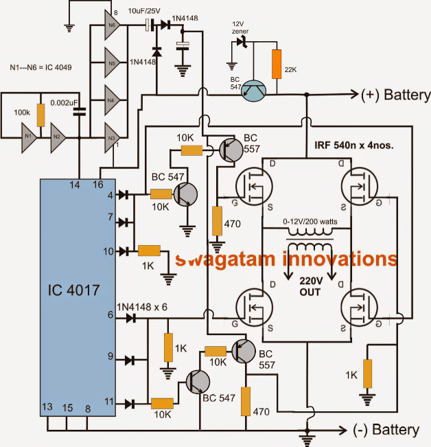 ,is it right to note that the oscillator ic is the C4017?
Evans, the oscillator is 4049 IC, the 4017 is the alternate switcher for the H bridge
Hi sir
I am trying to develop a full bridge inverter using 555 timer and 4017IC, how can I do this. how much on time should I set for mosfets?
Hi Ganesh, you can try the last concept presented in the following article, by replacing the BJT stage with a 4017 stage.
https://www.homemade-circuits.com/simplest-full-bridge-inverter-circuit/
Hi sir,am Evans do you mind sending circuit diagram of a full bridge inverter using ic cd4047? I would like to construct a 5000w inverter,thank you.
Hi Evans, you can try the first circuit from this article:
https://www.homemade-circuits.com/5kva-transformerless-inverter-circuit/
Hello sir,the circuit above uses 4049,but I would like one that uses CD4047 and a transformer without centre tap and n channel mosfets
Evans, please check the first circuit in the link which I gave you in the previous comment…
Hello good morning my name is Carlos from Argentina. I have a question, on the web I found this wave inverter circuit modifies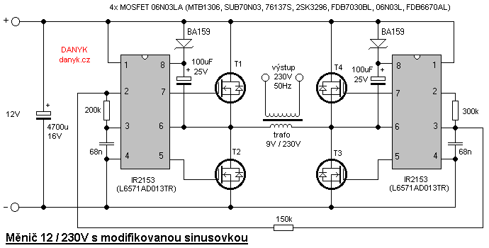 I want to know if it can really work? From already thank you very much.
Hi Carlos,
It will need to be tested practically, because as you can see the two ICs are cascaded with each other which is difficult to simulate in mind. So it will need to be tested for verifying the results.
Hello, good afternoon, my name is Carlos from Argentina, I am a faithful follower of the website. I want to build the inverter with lm555 and cd4017 with bridge H and 4 mosfet .. The question is I have a transformer of 12v x 15 amps without central cover how much power I will have output .. Thank you very much.
Atte: Carlos from Argentina
Thank you Carlos, you will be able to get a maximum of 12 x 15 = 180 watts, or may be around 160 watts
Can u explain me sir nand gate in ic 4049 with their pin number… Means which pin number 1,2,3,4…so on…because i can not find which pin 1 and which pin 10 and so on…
Apurva, I have updated the IC pinouts in the above article. But please note that I have not yet tested this design practically
Can i do this design for practically or not…
If you have understood the concept and confident about it, then you can do it.
And also suggest me that. can i do second cricuit diagram aur not…..i waiting for suggestion sir… If the first project will be not succeed then can i do second one where 2 ic is used 555 and 4017…
Ok sir i will waiting for tomorrow…
I have updated the design under this article:
https://www.homemade-circuits.com/2014/01/simplest-full-bridge-inverter-circuit.html
What Some cricuit miss out from given cricuit diagram..
I’ll update the missing things tomorrow!
Sir.. One more rply sir… Can i increase the transformer wattage if i connected two transformer which are 12v-0-12v… Actually i found this transformer from dvd player… And also share me what is the wattage of these transformer which are generally used dvd player…
Two transformers cannot be used, and it must 0-12V not a center tapped one.
Sir can u give cricuit diagram of ir2103 ic where it is used… I think it is present in my location…
You can try this diagram: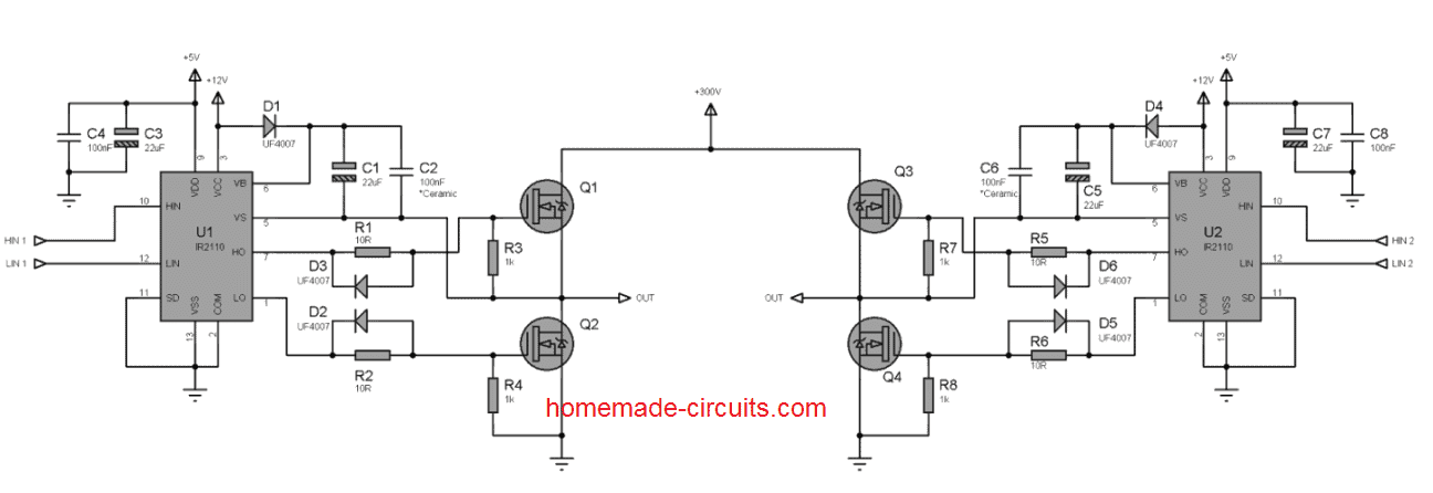
The HIN, LIN inputs can be supplied through an oscillator circuit, I’ll update it after sometime.
U know i am not fully experienced preson but i will do this project because it is my hobby… And one more thing is that is possible with ur support… Sir… I want know that.. Can this diagram is correct or not…i waiting for ur comments sir..
Hi Apurva, I won’t recommend the above idea to a newcomer, because this concept will require some serious understanding and optimizations.
I will again advise to go for an IC based full bridge inverter circuit….
Buy two of these ICs, and then you build a good full bridge inverter
https://www.infineon.com/dgdl/ir2103.pdf?fileId=5546d462533600a4015355c7b54b166f
does anyone have proteus library for SG3525 IC
dear Sir, how i control my inverter output voltage level. my inverter output voltage is 330 volt but i want 240 volt. please tell me about that. thanks
Dear Pizush, you can incorporate the following circuit with your inverter for correcting the issue:
https://www.homemade-circuits.com/2014/01/automatic-output-voltage-regulator.html
hii Mr. Swagatam… I have checked my HCF4049UBE on the google and found of its vdd is 10V, so .. this device still can be used for 12V vdd or needed to regulate it to 9V or should i go for 4049 with the specification more high (15V) VDD ??
no problem Hui, that sometimes happens:)
ow.. im sorry.. may be i little careless to see datasheet.. after i saw next page .. yess.. ur right sir the voltage supply is so wide .. .. i have been tricked with vdd 10v has pF ..on the first page.. i will careful next time.thx , sir..
Hi Mr.Hui, the IC HCF4049UBE is specified to work with supplies from 3 to 20V, so it can be used safely with a 12V supply, just as any other IC 4049 variant
Dear Swagatam Sir,
I tried to use 2 N MOS and 2 PMOS for inverter circuit.I used IRF540 and IRF 9540.But when I increase the supply voltage beyond 8 V,the current increases abruptly and my DC voltage source get shorted.Can you please figure out the problem?
Dear Faris, it will be difficult to troubleshoot because an H-bridge using N and P mosfets can be extremely unpredictable, that's why the use of specialized H bridge driver IC is recommended for implementing such topologies safely…
Hi swagatam
I put another diode on each leg of the 4017 outputs ie:2,4,7,10 and 5,6,9,11 and the output voltage rose to 220v.
When i put a load(4w) on the voltage drops considerably even after increasing the trafo wattage from 12w to 120w i still get quiet a big voltage drop, now to prevent this voltage drop would puting fet's in parrallel(ie doubling up on the mosfets) so as to entice more current to flow through the trafo solve the problem?
And would the 4017 ic be able to switch for instance 8 mosfets comfortably
Regards
Hi Robin,
If you are using a 120 watt transformer with a 100Ah battery and fets specified to carry currents above 20 amps then the voltage should not drop unless the load exceeds 120 watts.
so i don't think paralleling the mosfets would improve the results because the problem could be somewhere else.
yes the 4017 outputs and the BJTs are all capable enough to make any msfet trigger fully since the gate impedance of an FET is very high,
May be you could switch to a professional full bridge design using a single IC fully bridge driver as explained here:
https://www.homemade-circuits.com/2014/01/simplest-full-bridge-inverter-circuit.html
Hi Swagatam
The moment i connected a trafo i relized the fets were still not switching
I replaced the 1k resistor that i removed from the voltage doubler to the 557 emitter with a 100k resistor and got 23.5v at the emitter(which i think is correct?)But now it does'nt switch through to the collector.Remember previously i just had a wire.
I need that voltage to switch through to the collector and thus the High/side fet gates
Shoo,but i think we're getting there
cheers
Oh,I just want to mention that i am working with a 100AH battery,its big enough and fully charged
Hi Robin,
you may have to check the stages separately.
first disconnect the bases of the mosfets from the transistors, next disconnect pin14 from the 4049 clock and feed the clocks from an external oscillator at a very slow rate, may be at around 0.5 Hz.
Next, you can confirm whether the transistors are providing the required voltages at the intended levels over the indicated points or not.
Once this is confirmed then you can integrate the mosfets and continue checking the results without altering the 0.5 Hz sequence rate.
If there's any fault somewhere the above method will be able to trace it out.
Hi Swagatam
Just one other thing,the Zener diode part seems to bring the voltage down so i left that out and connected directly to the battery
cheers
OK no issues Robin, you are doing a great job
so far it's been very interesting, let's see what finally transpires from the efforts.
yes a 0-9V trafo would surely yield the required 230V
Hi Swagatam
I had my oscilloscope on ac instead of dc for channel 1 therefore could'nt pick up the voltage doubler reading(big mistake lots of time wasted)
Ok i got the fet's switching 100%,Trafo used=12W {220v in and 12vac 1000ma out}.
output voltage=180v if i used trafo=220 in and 9v out i would've got higher output voltage
I will e-mail you the images of 1) low/side fet gate voltages
2)high/side fet gate voltages
3)trafo output waveform(there are 6*10k resistors across the output,so i put the scope over one 10k)
I will e-mail you the images immediately
cheers
Thanks a lot Robin,
if possible please do send the images of the working prototype!!
Hi Swagatam
I got the fets switching properly now,I removed the 1k resistor from the voltage doubling circuit to the bc557 emitter and put a wire there.I didnt get any voltage there but got 21.2v at the collector.
In the other H-bridge circuit there is a resistor there,maybe there should'nt be?
There is an extra resistor at the top right high-side fet which i left out.
I'll do some further testing tomorrow
Hi Robin, that's great keep it up…
appreciate your outstanding efforts in verifying my circuits.
hi swagatam,
thank you for sharing your knowledge
I have implemeted your circuit but it has some problems.
the first is oscillating frequency. How 1 khz on the 4017 ic will be 50 hz on the h bridge?
The second is that the output is 220 volt ac without load but with load the volt decreases suddenly to 40 volt ac.
How could I preserve the volt with load?
Hi Ahmed,
I have divided the 1khzwith the total number of outputs used from the IC 4017, so 1000/10 = 100Hz, and this fvrequency when divided across two mosfet arms gives 50Hz.
You can adjust it as per your own calculations if the above results look incorrect.
The output voltage will depend on trafo wattage and battery AH capacity, they must be sufficiently rated well above the load wattage, otherwise it will drop proportionately.
ok sir thank you but sir please im still in the 4049 some of the pins is not shown in the circuit such as pin8 and pin16 i can see the pin8 is gnd or ground please sir where is the pin16 connect to? that is all my problem im looking forward to hear from you.
bianzz, what does the datasheet say about pin16? Please follow exactly as mentioned in the datasheet
hi sir in this circuit i want to ask you that the IC4049 please sir is N1 start from (2 to 3) and (N2 4 to 5) up to 15? i guess you are understand what i mean cos im confused about it i build it but it don't work that is why im asking maybe i didn't connected the pins correctly thank you sir im looking forward to hear from you son.
Hi bianzz, all gates inside the 4049 are identical so you can organize them as per your choice, only the input and outut pins of the selected gates needs to be connected correctly as per the diagram.
check the datasheet of this IC you will get the idea regarding the involved gate pinouts.
hi swagatam
this is srinivas cani use this design for 3kva transformer (0-36 volts)220volt out put,please suggest me
regards
Hi Srinivas,
yes you can use it.
Hi, Swag,
I am have built an inverter but the problem lies in the charging area in that when there is power from the mains and the inverter is charging, do we have to build a different charger for the inverter or we should allow the power mosfet to charge the battery.
Also what are the side effect of charging with the mosfet. And is it advisabe to build a different charger for the inverter.
Regards
Hi Itoro,
Which circuit are you referring too?
All inverters mostly use a separate transformer or winding for charging.
Without actually inspecting the circuit it will be difficult for me to comment precisely.
using solar panel as input can i get 600W at output side in this inverter circuit…??
and what should be the circuit and specification of transformer and solar panel….???
for 600 watts, the solar panel must be at least 200 watts rated and the transformer at 800 watts.
The battery should have minimum current capacity of 200ah.
Hi, thanks for reading my blog!
yes, you can send it to homemadecircuits@gmail.com
Quick question about the h-bridge, since I am using two voltage one for the oscillator and another voltage for the ac output, I read that I need to turn on the oscillator first then apply the high voltage DC second. Is this correct ? You are a wise man your word is gold. Everything I have built from you has worked, still working on the solar inverter, I have come a long way almost there.
Thank you for trusting my suggestions.
If you connect the AC output voltage to the mosfets first, while the oscillator is switched OFF then nothing will happen, since all the mosfets will remain switched OFF. However, in this situation if you switch ON the oscillator then initially for a fraction of a second the mosfets could be switched ON randomly causing short circuits or some unexpected results.
Therefore it is always a good practice to switch ON the oscillator fist and then switch ON the voltage to the mosfets
Good deal thanks, I have been playing around with a few of your circuits have not decided which one it will be a pure sign wave one, I was wondering what you thought of the Chinese version SPWM egs002
I have not yet used the mentioned product so I am not sure about its performance.
Ok no problem, I don’t trust the Chinese or there electronics. I sent you another message about that. Hay if all else fails with this module. I know where to get circuits that have been tested. Thanks for everything you have done. As they say in the U.S. you are a good man Charley Brown.
Many thanks for the complements, I appreciate it. Please keep up the good work!