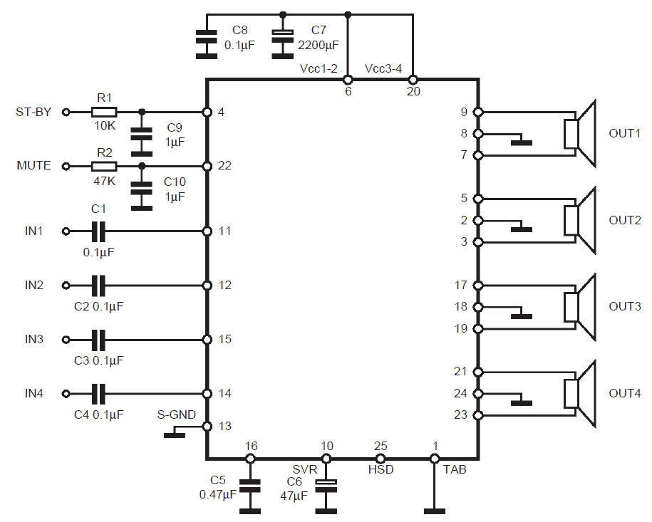
In this post I have explained the datasheet of the IC TDA7560 which is a cutting-edge BCD (Bipolar / CMOS / DMOS) technology class AB 4 x 45 quad Audio Power Amplifier in Flexiwatt 25 package made for super high power car radio.
The thoroughly interdependent P-Channel/N-Channel output composition makes it possible for a rail to rail output voltage swing which, linked with high output current and minimized saturation cuts sets latest power references in the car-radio niche, with optimal distortion activities.
DC OFFSET DETECTOR
The TDA7560 integrates a DC offset detector to evade that an anomalous DC offset on the inputs of the amplifier could possibly be multiplied by the gain and contribute to an unfavorable significant offset on the outputs that might cause speakers problems for overheating.
The feature is allowed by the MUTE pin and fits well with the amplifier umuted and without signal on the inputs. The DC offset diagnosis is signaled out on the HSD pin.
STAND-BY AND MUTING STAND-BY and MUTING facilities are both CMOS-COMPATIBLE. In shortage of correct CMOS ports or microprocessors, an immediate connection to Vs of these two pins is admissible still a 470 kOhm similar resistance ought to give between the power and the muting together with stand-by pins.
Specifications:
Fantastic OUTPUT POWER Potential:
4 x 50W/4 Ohm Maximum.
4 x 45W/4 Ohm EIAJ
4 x 30W/4 Ohm @14.4V, 1KHz, 10%
4 x 80W/2 Ohm Maximum.
4 x 77W/2 Ohm EIAJ
4 x 55W/2 Ohm @14.4V, 1KHz, 10%
EXCELLENT 2 Ohm DRIVINGCAPABILITY
HI-FI CLASS DISTORTION
Minimal OUTPUT NOISE
ST-BY Functionality
MUTE FUNCTION
AUTOMUTE AT MIN. SUPPLY VOLTAGE Identification
Minimal Outside COMPONENT Estimate:
– INTERNALLY Predetermined GAIN (26dB)
– NO EXTERNAL COMPENSATION
– NO BOOTSTRAP CAPACITORS
ON BOARD 0.35A HIGH SIDE DRIVER
PROTECTIONS:
OUTPUT SHORT CIRCUIT TO GND, TO VS,
ACROSS THE LOAD
VERYINDUCTIVE LOADS
OVER RATING CHIP TEMPERATURE WITH
SOFT THERMAL LIMITER
OUTPUT DC OFFSET DETECTION
LOAD DUMP VOLTAGE
FORTUITOUS OPEN GND
REVERSED BATTERY
ESD


Questions & Answers
Apparently with no real reason the Module gets extremely hot that not possible to touch
How much supply voltage did you use?
Olá Swagatam, gostaria de montar um circuito com o TDA7560, sendo 2 canais satélites e 2 canais em BRIDGE, você poderia ajudar-me? Não tenho conhecimento suficiente para fazê-lo. Caso positivo, gostaria de saber se você teria como fazer uma placa, e, óbviamente dizer quanto custa. Agradeço, um abraço.
Hi Adelcio, I am sorry, I too have no idea how to connect amplifiers in bridge network correctly. I wish I could do it for you!
Hi sir,
I have a car stereo that using a tda7560 ic,the problem the unit is having no audio output,i already replaced the ic,but the problem still not solved.What does HSD pin in the IC #25.Is this plays an important role in the circuit?
Hi Enerio, the HSD is not important because it is an output pin, and associated by an internal auto mute function, it is an unused output for most applications so nothings critical about it.
Check all the solder joints and tracks, there could be a open track or a short circuited track. Clean the PCB with acetone to make sure everything is crystal clear.
Hello good afternoon, my name Carlos and I am a faithful follower of the web sites. I have the FM radio in my car that has very poor reception, could you design a simple circuit to amplify the FM / AM signals … Thank you very much
Hello Carlos, car FM radios are usually very powerful and provide high quality reception….FM radio better than car radio can be difficult to design.
i have 2 separate tda 2050 mono boards working separately fine—-but if i bridge them—-huge distortion–slight song coming out——————-c1 cap wrong given—-i have reversed polarity—-i have +/- 22 v dc
———-is there anything wrong ?
—-thank you
I don’t think there’s anything wrong in doing so, and its polarity has nothing to do with output distortion….
thank you—–so i will try it again making same circuit
is it possible to use this ic at 1ohm load? have anybody tried that ? will it fall in to protection or just break?
If i give 24 5amps to 1 4191 ic it will make Heat or damage sir …for single IC
check the datasheet for the maximum voltage limit…if that exceeds then the IC may get damaged….
In Tda 7560…
If i use 18v 10 amps the ic will ba damage or not
No it won't
Another 1 doubt regarding stk4191
O/p power is 100watts….for 1 ic
If i use 24v 3Ampere 72watts only come…
5 ampere means 120watts…
What should i do sir….
I'm using 2 ,12inch subwoofer 8ohms 50watts sir…
Guide me sir
to get optimal response from the IC you must use more than 5 amps
Anothet 1 doubt abt Tda 7560…
Power supply of this ic is dual or single power supply..i think it is single power supply correct sir…
Shall i use 18v 3.5A transformer
Or 24v 3A transformer….
Tell the Voltage and Amps rating of this IC…
another 1 big doubt sir….
How to calculate the SPEAKER watts and Coil size bcs some speaker back side not mentioned….I can check ohms by using multimeter..but watts and coil size i do no to check…
Pls guide me sir
sorry I have no idea of the method of identifying the exact specs of an unknown speaker
it's a single supply IC.
18V is OK but 3.5 amp may be inadequate to drive 4 subs.
each sub may be minimum 45 watts rated, so dividing this with 18 gives 2.5 amps
therefore you might need a power supply rated at 18V 10amps (2.5 x 4)
I need Microphone pre amplifier circuit sir
sorry here's the link
https://www.homemade-circuits.com/2016/05/how-to-build-microphone-amplifier.html
Hai sir…
1.I'm using stk4141 for 12inch Danity subwoofer…its working well…
Is this combination is correct or we should want to change…sir,,
I'm using 24.0.24v 3 Ampere transformer for onyl subwoofer….is this sufficient ?…
Sir i need microphone circuit….
Circuit must be like Microphone circuit to power Amplifer audio input…
Without noise and distortion sir…pls sir
Hi Kesava,
24 x 3 = 72 watts, if your sub speakers are below this value and you are satisfied with the sound level then it's OK.
you can try the following MIC circuit for your requirement
What is the Transformer rating 18V or 28V and Current rating 750mA is enough?
Dear Sir,
Thanks very much
use 6A4 diodes
Dear Sir,
What diode should be used for rectification?
Dear Sir,
Thanks
it should be 28V, or a 24V will also do….750mA won't work that's too low, it should be at least 5 amp
Hi Sir,
Once rajeesh,
As instructed by you fish tank ckt is working great this credit goes to you.
and help me in amplifier ckt – what speaker rating suits for TDA7560 ?
Thanks Rajeesh,
you can use any 50 watt 4ohm speaker for the above explained amplifier
Hello Amresh, The datasheet has no detailed information regarding the pins 4, 22, so I think you will have to check it by trial and error.
By the way R2 is 47K resistor not 47 ohms
initially keep these pins unconnected and check the response…..the input must be fed with a music signal which must have a peak voltage of minimum 1V, below this the amp may not respond….or you can simply touch the inputs with your finger to see whether or not the speakers starts buzzing loudly…
Hello sir
I am working on a audio amplifier board with ic TDA 7560. There is no audio out. The standby pin is at 6.5v n mute pin is at 0v. When I connect mute pin to 13v Vcc through a 47 ohms 1watt resis it starts heating up quickly. About 170ma of current flows through it.
Can u pls hlp me out..??