When a DC to AC inverter is operated through a solar panel, it is called a solar inverter. The solar panel power is either directly used for operating the inverter or it's used for charging the inverter battery. In both the case the inverter works without depending on mains utility grid power.
Designing a solar inverter circuit essentially requires two parameters to be configured correctly, namely the inverter circuit and the solar panel specs. The following tutorial explains the details thoroughly.
Building a Solar Inverter
If you are interested to build your own solar inverter then you ought to have a thorough knowledge of inverter or converter circuits, and regarding how to select solar panels correctly.
There are two options to go about from here: If you think making an inverter is much complex, in that case you could prefer buying a ready made inverter which are plentifully available today in all sorts of shapes, sizes and specs, and then simply learn only about solar panels for the required integration/installation.
The other option is to learn both the counterparts and then enjoy building your own DIY solar inverter step wise.
In either case learning about solar panel becomes the crucial part of the proceedings, so let's first learn about this important device.
Solar Panel Specification
A solar panel is nothing but a form of power supply which produces a pure DC.
Since this DC is dependent on the intensity of the sun rays, the output is normally inconsistent and varies with the sun light position and climatic conditions.
Although solar panel is also a form of power supply, it significantly differs from our usual home power supplies using transformers or SMPS. The difference being in the current and voltage specs between these two variants.
Our home DC power supplies are rated to produce higher amounts of current, and with voltages perfectly suiting a given load or application.
For example a mobile charger may be equipped to produce 5V at 1 amp for charging a smart phone, here the 1 amp is amply high and the 5V is perfectly compatible, making things extremely efficient for the application need.
Whereas a solar panel may be just the opposite, it usually lacks current and may be rated to produce much higher voltages, which could be hugely unsuitable for general DC loads such as a 12V battery inverter, mobile charger etc.
This aspect makes designing a solar inverter a little difficult and requires some calculations and thinking in order to obtain a technically correct and efficient system.
Selecting the Right Solar Panel
For selecting the right solar panel, the basic thing to consider is that the average solar wattage must not be less than average load wattage consumption.
Let's say a 12V battery needs to be charged at 10amp rate, then the solar panel must be rated to provide a minimum of 12 x 10 = 120 watts at any instant as long as there's a reasonable amount of sun shine.
Since generally it is difficult to find solar panels having lower voltage and higher current specifications, we have to move on with what is readily accessible in the market (with high voltage, low current specs), and then dimesnsion the conditions accordingly.
For example if your load requirement is say 12V, 10 amps, and you are unable to get a solar panel with this specs, you may be forced to opt for an incompatible match such as a 48V, 3 amp solar panel which looks much feasible to procure.
Here the panel provides us with voltage advantage, but current disadvantage.
Therefore, you cannot connect a 48V/3amp panel directly with your 12V 10 amp load (such as a 12V 100 AH battery) because doing this would force the panel voltage to drop to 12V, at 3 amps making things very inefficient.
It would mean paying for a 48 x 3 = 144 watt panel and in return getting 12 x 3 = 36 watt output...that's not good.
In order to ensure an optimal efficiency we would need to exploit the voltage advantage of the panel and convert it into a equivalent current for our "incompatible" load.
This can be very easily done using a buck converter.
You will Need a Buck-Converter for Making a Solar Inverter
A buck converter will effectively convert the excess voltage from your solar panel into an equivalent amount of current (amps) ensuring an optimal output/input = 1 ratio.
There are a few aspects here which needs to be considered. If you are intending to charge a lower voltage rated battery for later use with an inveter then a buck converter would suit your application.
However if you intend to use the inverter with the solar panel output during daytime simultaneously while its generating power, then a buck converter would not be essential, rather you could connect the inverter directly with the panel. We will discuss both these options separately.
For the first case where you might need to charge a battery for later use with an inverter especially when the battery voltage is much lower than the panel voltage, then a buck converter could be imperative.
I have already discussed a few buck converter related articles and I have derived the final equations which can be directly implemented while designing a buck conveter for a solar inverter application, you may go through the following two articles for getting an easy understanding of the concept.
Calculating Voltage, Current in a Buck Inductor
After reading the above posts you might have roughly understood regarding how to implement a buck converter while designing a solar inverter circuit.
If you are not comfortable with formulas and calculations, the following practical approach could be employed for obtaining the most favorable buck converter design output for your solar panel:
Simplest Buck-Converter Circuit
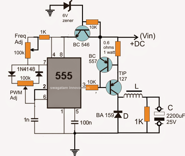
The above diagram shows a simple IC 555 based buck converter circuit.
We can see two pots, the upper pot optimizes the buck frequency, and the lower pot optimizes the PWM, both these adjustments could be tweaked for getting an optimum response across C.
The BC557 transistor and the 0.6 ohm resistor forms a current limiter for safeguarding the TIP127 (driver transistor) from over current during the adjustment process, later this resistance value could be adjusted for higher current outputs along with a higher rated driver transistor.
Selecting the inductor could be tricky.....
1) The frequency may be related to the inductor diameter, lower diameter will call for higher frequency and vice versa,
2) Number of turns will affect the output voltage and also the output current and this parameter would be related to the PWM adjustments.
3) The thickness of the wire would determine the current limit for the output, all these will need to be optimized by some trial and error.
As a rule of thumb, start with a 1/2 inch diameter and number of turns equal to the supply voltage....use ferrite as the core, and after this you can begin the above suggested optimization process.
This takes care of the buck converter which can be used with a given higher voltage / low current solar panel to obtain an equivalently optimized lower voltage / higher current output, as per the load specs, satisfying the equation:
(o/p watt) divided by (i/p watt) = Close to 1
If the above buck converter optimization looks difficult, you could probably go for the following tested PWM solar charger buck converter circuit option:
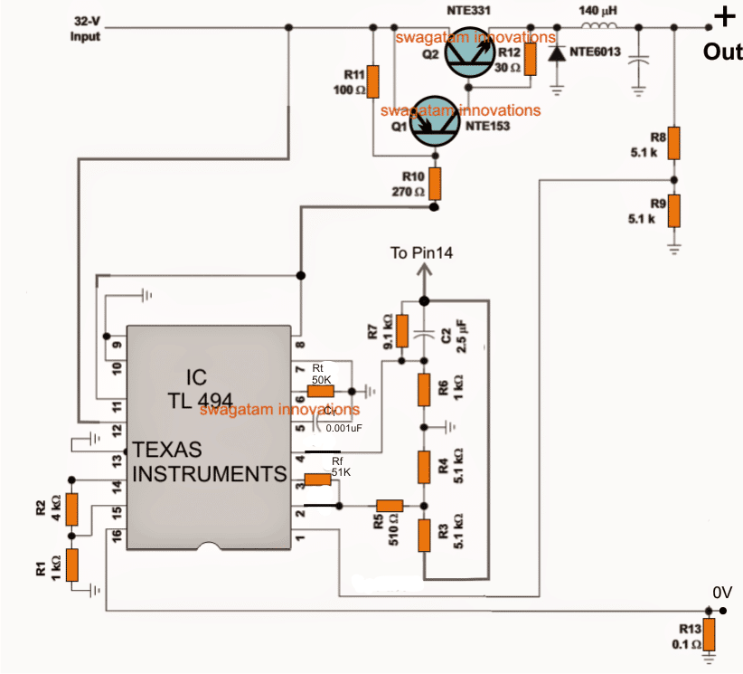
Here the R8, R9 can be tweaked for adjusting the output voltage, and the R13 for optimizing the current output.
After building and configuring the buck converter with an appropriate solar panel, a perfectly optimized output could be expected for charging a given battery.
Now, since the above converters are not facilitated with a full charge cut off, an external opamp based cut-off circuit might be additionally required for enabling a fully automatic charging feature as shown below.
Adding a Full Charge Cut-off to the Buck Converter Output
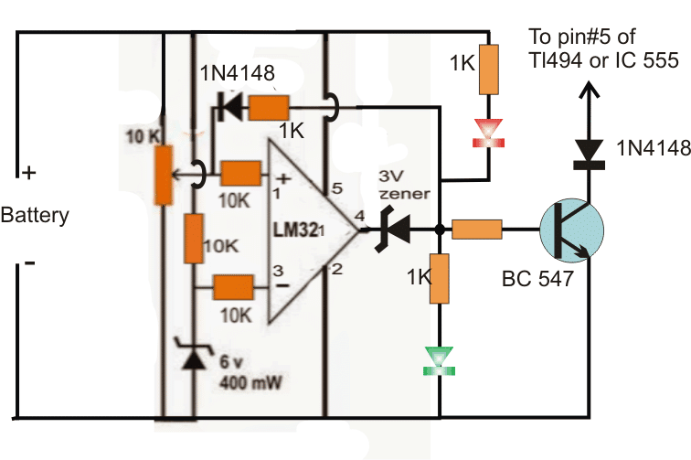
- The shown simple full charge cut-off circuit could be added with any of the buck converters for ensuring that the battery is never over charged once it reaches the specified full charge level.
- The above buck converter design will allow you to get a reasonably efficient and optimal charging for the connected battery.
- Although this buck converter would provide good results, the efficiency could deteriorate as the sun went down.
- To tackle this, one could think of employing a MPPT charger circuit for acquiring the most optimal output from the buckcircuit.
- So a Buck circuit in conjunction with a self optimizing MPPT circuit could help in churning out the maximum from the available sun light.
- I have already explained a related post in one of my previous posts, the same could be applied while a solar inverter circuit design
Solar Inverter without a Buck Converter or MPPT
In the previous section I have explained to design a solar inverter using a buck converter for inverters with lower battery voltage rating than the panel and which are intended to be operated during night time, using the same battery which was charged during the day time.
This conversely means that if the battery voltage is upgraded somehow to match approximately with that of the panel voltage then a buck converter could be avoided.
This may be also true for an inverter which may be intended to be operated LIVE during daytime, meaning simultaneously while the panel is generating electricity from sunlight.
For simultaneous day time operation, the suitably designed inverter could be directly configured with a calculated solar panel having the correct specifications as shown below.
Again we must make sure that the average wattage of the panel is higher than the maximum required wattage consumption of the inverter load.
Let's say we have an inverter rated to work with a 200 watt load, then the panel must be rated at 250 watts for a consistent response.
Therefore the panel could be a 60V, 5 amp rated, and the inverter could be rated at around 48V, 4amp, as demonstrated in the following diagram:
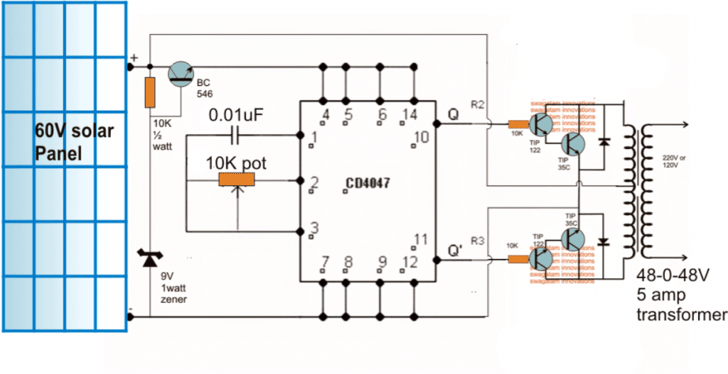
In this solar inverter, the panel can be seen directly attached with the inverter circuit and the inverter is able to produce the required power as long as the sun rays are optimally incident on the panel.
The inverter would keep running at a reasonably good power output rate for so long as the panel produces voltage above 45V...... that is 60V at the peak and down to 45V probably during afternoon.
From the above shown 48V inverter circuit it is evident that a solar inverter design does not need to be too crucial with its features and specifications.
You can connect any form of inverter with any solar panel for getting the required results.
It implies that you can select any inverter circuit from the list, and configure it with a procured solar panel, and begin reaping free electricity at will.
The only crucial but easy to implement parameters are the voltage and the current specifications of the inverter and the solar panel which must not differ by much, as explained in our earlier discussion.
Modified Square wave Solar Inverter Circuit
All the designs which are so far discussed are intended to produce a squarewave output, however for some application a square wave could be undesirable and might require an enhanced waveform equivalent to a modified sine wave. For such requirements a PWM operated circuit could be implemented as shown below:
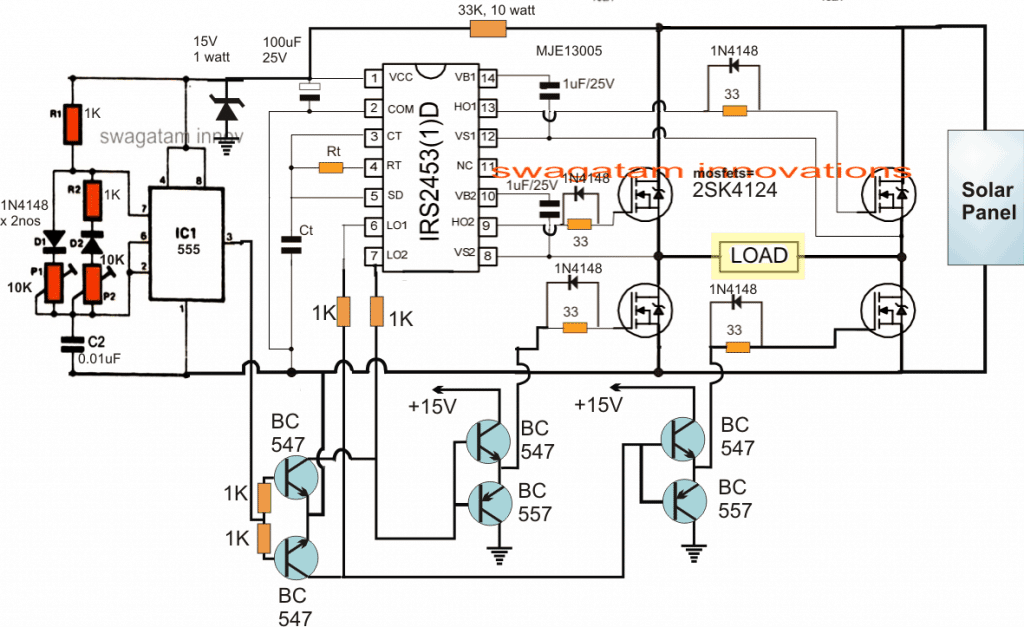
Note: The SD pin#5 is mistakenly shown connected with Ct, please make sure to connect it with ground line and not with Ct.
The above solar inverter circuit using using PWM sine wave can be studied elaborately in the article titled 1.5 ton AC solar inverter circuit
From the above tutorial it is now clear that designing a solar inverter is after all not so difficult and could be efficiently implemented if you are equipped with some basic knowledge of electronic concepts such as buck converts, solar panel and inverters.
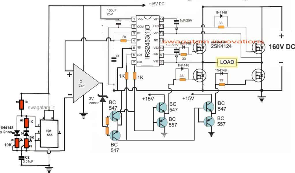
A sinewave version of the above can be seen in the following diagram, which works using an SPWM chopping for the low side mosfets :
Still confused? Do not hesitate to use the comment box for expressing your valuable thoughts.
Remember, a solar inverter is as easy as hooking up any standard inverter to a solar panel, ensuring that the solar panel voltage is only slightly higher than the inverter operating DC specs.
If you want any customized solar inverter circuit of your choice designed by me here, please feel free to put the request through the below comments, I will try to fulfill it as soon as possible.
Conclusion
Designing a solar inverter can be a complex process that involves a good understanding of electronics, power systems, and solar energy. Here are some general steps to consider when designing a solar inverter:
- Determine the load requirements: The first step in designing a solar inverter is to determine the load requirements. This will include the power requirements of the load, as well as the type of load (i.e., resistive, inductive, or capacitive).
- Determine the solar panel specifications: The second step is to determine the specifications of the solar panels that will be used with the inverter. This will include the voltage and current output of the solar panels, as well as their maximum power point (MPP) voltage and current.
- Choose the inverter topology: The next step is to choose the inverter topology that will be used. There are several different types of inverter topologies, including transformer-based and transformerless designs.
- Select the components: Once the inverter topology has been chosen, the next step is to select the components that will be used in the inverter. This will include selecting the power semiconductors (i.e., MOSFETs, IGBTs), capacitors, inductors, and resistors.
- Design the control circuit: The control circuit is an important component of the inverter, as it regulates the voltage and current output of the inverter. The control circuit will include a microcontroller, voltage and current sensors, and a feedback loop.
- Build and test the prototype: Once the design is complete, it is important to build and test a prototype of the inverter to ensure that it meets the specifications and performance requirements.
It is important to note that designing a solar inverter can be a complex process that requires a good understanding of electronics and power systems. It may be helpful to consult with a qualified engineer or to use a pre-designed inverter kit or module.

Comments
Hi Sir Swagatam,
I`ve just found your site. Thank you very much sharing with us such useful info!
I have 2 questions related to this circuit
https://www.homemade-circuits.com/wp-content/uploads/2017/10/3000-watts.jpg
1. Can i supply it with 400DC instead 160DC
2. What is the max output power at 220AC I can get from this schema assuming I can supply enough DC on it input (not from solar panels)
BR
Asen
Thank you Asen,
You can use 400V instead of 160V, provided the mosfets are rated to handle 500V or 600V.
At 220V, the mosfets can provide maximum output power of 220 x 5 = 1100 watts
Thank you very much Sir Swagatam for your answer.
One more question I have for value of gate resistors here https://www.homemade-circuits.com/wp-content/uploads/2017/10/3000-watts.jpg.
On schema they are 33 ohm, but here https://www.homemade-circuits.com/mosfet-protection-basics-explained-is/ you stated:
“With relatively lower frequencies(50 Hz to 1kHz), the value could be anywhere between 100 and 470 ohms, while for frequencies above this the value could be within 100 ohms, for much higher frequencies (10kHz and above) this must not exceed 50 ohms.”
I need output frequency 50 hz so can I use 330 ohm gate resistors instead 33 ohm?
BR
Asen
Hi Asen,
You can try 330 ohms but lower value is recommended to ensure quicker discharge of the gate capacitance of the mosfet. Otherwise the mosfet can heat up. Therefore you can try 330 ohms, if you find the mosfets getting hotter, you can reduce the resistor values to 100 ohms or 50 ohms.
Hi Sir Swagatam,
I took into consideration your notes and have used directly 68omh resistors. Now the below schema is ready https://www.homemade-circuits.com/wp-content/uploads/2017/10/3000-watts.jpg
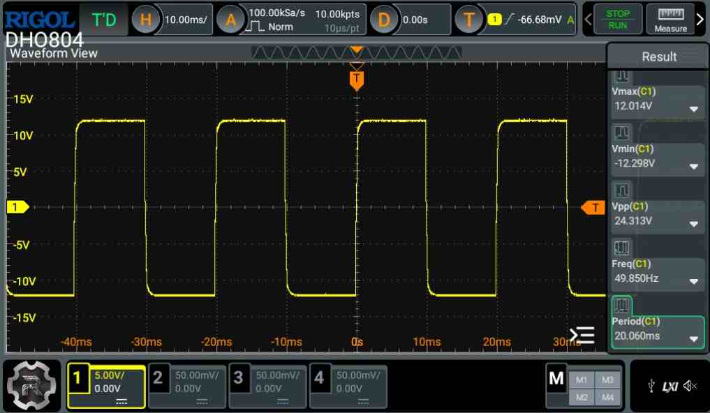
and I am going to put it in operation. In order to do this I want you to verify every my step. I`ve started with connection of 15v ONLY and settled 50Hz on (+)input on IC741. Also have set 50Khz on its (-) input. I want to show you the oscilloscope pictures taken on both these points as well on output point (pin 6) of IC 741.
Can you give me your mail to send these snapshots?
I can`t find such functionality here on site.
BR
Asen
Hi Asen,
I would recommend you to go step-wise.
Initially, start with the inverter only, do not build the 741 and the 555 circuits.
First build the basic IRS2453 inverter and check with 400V DC. It should convert the 400V DC into 400V AC square wave.
Please try this first….once this is implemented successfully then we can proceed with the 741 and 555 integration.
My mail address is hitman2008 @ live . in
You can send the images in my email but we will do the discussions through comments only, on this platform
Hi Sir Swagatam,
I just found your very very useful site. Thank you very much for the info you present here!
I have below question:
This circuit https://www.homemade-circuits.com/wp-content/uploads/2017/10/3000-watts.jpg
is almost the same like last part of https://www.homemade-circuits.com/wp-content/uploads/2016/02/pwm2Binverter2Bcircuit.png.webp circuit. Does it means I can dry 5kvar from first circuit in case i supply it with enough power rated on 400V (not from solar panels)?
I mean to apply 400v with enough power at input stated 160v on the first circuit?
BR
Asen
Thank you asko68,
Yes you can 400V instead of 160V, nbut you have to make sure the mosfets are rated to handle 500V or 600V.
Greetings Swagatan,
My inverter use to charge battery with both solar and electricity powers.
One evening, component inside blew up due to fluctuations in electricity and it did not charge the battery again. However it was taking on electrical power and I can work on my desktop using the direct solar panel power. But that is intermittent.
I uncoupled and found just one capacitor (VCR 1OD431K) blown.
COULD THAT BE THE ONLY PROBLEM?
WILL IT CHARGE THE BSTTERY AGAIN IF THE CAPACITOR IS REPLACED?
I removed the capacitor and went to get a replacement, but I could not find the matching value.
CAN I REPLACE IT WITH A BIGGER DIFFERENT TYPE (CNR 14D391K)?
Hello Archer,
that is not a capacitor, that is a varistor or an MOV. It could have been blown due to a voltage surge, and this might have also blown other electronic parts in your charger circuit. I don’t think just by replacing the MOV will help to restore the charger….you may have to check deeper to investigate the other faults.
Thank you
Hi Swagatam.
I have been following up on your articles since some 5years back and am amazed by how much renewable energy systems have come to be so reliable. I would like to get replacement pcb for hybrid mppt charger inverters. How do I go about it. This is because sometimes I am facing challenges when performing fault tracing on the modern PCBs and thought to save time would be to simply get the motherboard replaced. Thank you.
Thank you Michael, for being a dedicated follower of this blog. MPPT specifications can vary a lot depending on the solar panel and the load specs, so it can be very difficult to create a universal MPPT motherboard.
Hi Swagatam,
Since my solar panel has low current, I guess i will need a buck converter to charge my 12v 100AH battery from my solar panel with the following ratings:
nominal peak power = 190w
open circuit voltage = 46.2v
short circuit current = 5.42A
Max power voltage = 38.6v
Max power current = 4.92A
fuse rating = 10A
Max system voltage = 1000VDC
Can I use the buck converter with 555 IC or the one with TL494 IC? I am asking since buck convert can help boost the current
Hi Joe,
yes a buck converter will step dowm the voltage and boost the current for your battery. You can use the TL494 buck converter circuit
or you can also refer to the following post for getting the required design:
https://www.homemade-circuits.com/dc-to-dc-converter-circuits-using-sg3524-buck-boost-designs/
GOOD MORNING. IS THERE AN PLAN TO CONNECT THE INVERTER WITH THE 220 VOLT NETWORK? WITHOUT INVERTER BURNING?
Creating a GTI system can be complex, not possible with the designs explained in the above article.
hi, i intend to make an inverter that can the battery can be charged by both mains and solar cells, kindly help with a suitable design
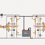
Hi, I have the updated the required changeover diagram just above the buck converter heading…
Hi Swagatam,
I intend to make a Solar inverter with 250-300 Watt output, 50 Hz at 230 V, so that it can power 8 single phase induction motors, each of 25 watt power. this is my major project. Solar panels of 250 watts and 320 watts are available. Which of the above circuits do you suggest for the project?
Hi Souvik, you can use the following design and see how it works:
the solar panel should be rated at 310 V 2 amps
Hi Swagatam ,
Only one question Sir, is it not an imperious care to make a small delay ( about 3 to5 ms) low level between the respective on states of Q2 and Q4 ways to avoid the risk of a short circuit during their simultaneous alternative commutation ?
All my thanks
Hi Franck, in ICs like SG3525, 4047, IRS2453, TL494 all have this feature (dead-time) in-built and therefore are fail proof in this regard
Hi Swagatam, OK, thank you very much Sir for your quick answer.. I did’not know that in-built. I have some SG3525 ICs.
Best Regards Franck
You are welcome Franck!
But the maximum output voltage available from commercially made solar panels do not exceed 45 V. So, is there anything else that can be done for getting the required output?
Looking forward to your reply.
You can use a 60 V solar panel instead and apply the 3rd circuit from bottom, in the above article. A transformer will be required if a 60 V panel is used.
i have a 24v 50a mppt charge controller, and 24 v 1600va inverter how can i integrate so that the power from pannel can be used to run inverter as well as to charge the battery,but i want to fix battery charging current max 20 amps either through solar or inverter charge.just to avoid over current situation.
You can connect the MPPT output directly with the inverter, and through a current limiter circuit for the battery. The current limiter can be a transistor based as explained in the following post:
https://www.homemade-circuits.com/universal-high-watt-led-current-limiter/
Sir can we make solar based induction cook top and what are the material required for it. Kindly inform please.
Hi Ankita, for making a solar induction heater, you can modify the coil of the first circuit from the following article into a flat coil, then connect it with a 36V 10 amp solar panel.
https://www.homemade-circuits.com/simple-induction-heater-circuit-hot/
Sir I want to know how to implement solar energy in induction cook top so that it can operate on solar energy as well as from electricity
Hello Ankita, are you referring to a ready made induction cook top for operating with solar panel? In that case you will require an inverter, or may be a 310V solar panel and a transformerless inverter. Please clarify this point I’ll try to help?
Dear Swagatham,
will you please help me to design an IGBT driver module, for Constant Current Regulator, (usually 5 pre-determined current steps) with varying AC voltage output to keep the output current at a predetermined level, ie 6.6 Amps or 20 Amps etc.
A UPS of 5 Kwatt to 30 Kwatt with this feature (Constant current @ fixed 5 steps) usually having out put voltages ranging from 1.2 KV to 5 KVolts is preferred.
The Circuit can be of Arduino or IRS 2413 based.
Thanking you in anticipation,
Pradeep KT
Dear Pradeep,
I could not find any IC with the number IRS2413, please provide me its datasheet then I will try to figure out the design….
Sorry for the mistake, the IC meant was IRS 2453(1)D or any equivalent.
I think the 3rd diagram from this article can be tried:
https://www.homemade-circuits.com/3-phase-induction-motor-speed/
The 1 ohm current limiter could be replaced with a rotary switch and multiple resistors for the appropriate selection of the current limit.
hi sir, i bought a step-down 230v to 12v , 125va transformer by mistake. would it be possible to still use it in the solar inverter circuit.
thank you
Hi Sahal, step-up and step-down are one and the same, it depends which way round you use it…so definitely you can use the transformer, if your load is within 125 VA
Mr Swagatam good day. Pls I need a solar generator circuit that includes grid energy meter to record the generator supply consumption. 12V or 24V input, 220V or 230V output, 2000watt and above. Or any one you can think of, thanks.
Hello Dominic, there are many inverter circuits explained, please go through them and select the one which looks suitable for you…all will work as per your desired specifications. for the power meter you can refer to this article:
https://www.homemade-circuits.com/simple-power-meter-circuit/
Can i have the video of the above explanation thanks
If possible I’ll try to make one soon
Thanks so much
Hi sir could you please advise me. I need to build a solar inverter with a battery that should power a home appliance. Please advise me as to how I should go about designing and which inverter design should be most appropriate.
Thank you
Hi Sahal,
You can estimate all the required parameters by calculating them as explained in the following article:
https://www.homemade-circuits.com/how-to-calculate-and-match-solar-panel/
Sir I’m willing to convert a 650VA UPS from battery power to solar power ⛮ sir I need help
Tun, you can do it by appropriately calculating the solar panel for your batteries:
https://www.homemade-circuits.com/how-to-calculate-and-match-solar-panel/
Hello Swagatam.I’d like to ask you if you are aware of Potential Induced Degradation (PID) problem of solar panels.I have searched for devices in the internet but they are too expensive.Do you have a circuit for this problem?Thanks in advance.
…it seems the solution is already discussed in this pdf document:
https://www.waaree.com/documents/FAQ_Potential_Induced_Degradation_White_Paper.pdf
Thanks Nick, I wasn’t aware of it until now, I studied about the phenomenon, and it seems the problem is more associated with the manufacturing process of the panel, and we might see this being appropriately rectified in the future panels.
I am not very sure of the reversing process, perhaps tying one of the AC terminals of the inverter output with the panel glass could help neutralize the effect. The alternating current from the inverter might break the development of the ions and prevent the process. Just a hypothetical suggestion, can’t be sure until this is verified practical.
Hi Sir Swagatam here I got a circuit from a friend and need your help to integrate an NE555 to turn it into a pure sine wave at the 220v output. I’ll send you the schematic to your email.
Thanks in advance
Hi xkaliber, you will have to apply the following theory for converting your design into a sine wave inverter:
https://www.homemade-circuits.com/how-to-modify-square-wave-inverter-into/
boa tarde. Este inversor de onda seno, qual a voltagem do painel solar? Qual valor deste diodo logo acima do 555 ? estas saidas de 15v dos transistor são ligadas no transformador? desculpa mas preciso montar um inversor mas não entendo muito, obrigado.
Hello, solar panel voltage will be 310V for 220V output. Please see the last diagram.
+15V will go to the 15V zener cathode point.
hi sir,
i am making a hybrid energy system using dc wind motor 50watt and solar penal of 30watt .sir can i connected both sources in series or parallel ?? and then make a single charge controller 100watt for charging the battery ?? i make a relay base circuit inwhich i turn off both sources if battery full charge .kindly refer me charge controller to control both sources ??
please give me your email i will send you circuit diagram .kindly check it and give your important suggest
Hi Ali,
You can connect them in series after rectification through bridge rectifiers for both the sources. Then connect this voltage to a buck converter or a boost converter for charging your battery
Hello sir, i have a LiPo battery of 7.4 V and current of 2000mAmp…My solar panel produces power of around 38.4Watt. Please suggest me which inverter I can use.
A 6V regulator cannot be used with a LM338 and it can neither be connected directly to the battery since it has lower voltage level than the battery.
you will need a boost converter for this.
you an try a joule thief concept for achieving this, as given in the following article
https://www.homemade-circuits.com/2012/10/1-watt-led-driver-using-joule-thief.html
the coil winding will need to be optimized for the 6V input and the 7V output
sorry I am not sure from where a similar unit could be obtained readymade…
Thank you for the help. The voltage and current from the panels will be around 6V and 5.6A. So do you think LM338 will work? and is there a way that I can order this regulator from somewhere? and also what will be the weight or size of this regulator? (because weight and size is an important factor for my project)
Hello Rahimul, if the voltage from the panel is within 12V then you can use an LM338 regulator as the controller for charging your cell
Hello sir, I have a LiPo battery of 7.4V and 2 Amp so which inverter do you think i should use… my solar might produce power of around 38.4 Watt
HI swagatam , I have an urgent need to come up with something similar to the above inverter, My Power requirement is 750 Watt, Ac 220 V.Can you please advise on the Watt Panel I will require , Transistor Specs , and lastly can I add MPPT feature to this design
MPPT will make the design a a lot complex..
it's better to manually adjust the solar panel angle every after 3 hours
Hi Lufono, you can try the last design from the above article, you will require a 350V solar panel, rated at 3 amp minimum.
you can connect this output directly with the last circuit for the required results, but ofcourse after suitably optimizing the PWM
Hi Swagatam , on the above circuit , what modification do i need to make to atleast get 1500 Watt 230 AC directly from the sun , how many solar panel of what size rating and how many transistors on the inverter itself , Thanks in advance
Hi VHAFUWI, ideally a 2000 watt panel will ensure a consistent 1500W for a much longer period of time throughout the day from your inverter
the transistor will need to be specified as per the voltage and amperage of the panel that you may prefer.
Sir i have sent the image plz have a look
show me schematic, PCB will not do!
Hii sir..i have a query…i have a three phase monitoring relay made by L&T in this relay energies after 5 seconds of proper e phase supply..can this time extend upto 60 seconds
Munim, I am not available on Whatts app….you can send the pics in my email
admin at http://www.homemade-circuits.com
Sirr i have photos of circuit…how can i send you..my whats nmbr +919812387940 if you please contact me…please..its very urgent i am working with indian railway and its urgent requirement…please
You may have to modify the internal circuit of the unit or use the following circuit externally for operating the L&T relay after 55 seconds
https://www.homemade-circuits.com/2013/02/make-this-simple-delay-on-circuit.html
Sir, This post is more useful for me but I have a doubt sir. I sine wave inverter weather we get a purest sine wave form without lc low pass filter?????
OK sir. Thanks for your comment and sharing of knowledge
Vijay, it's normally in the form of LC filter, but still the output can never be exactly line real sine wave, it can be accomplished only through an audio amp set up but the losses will be high due to device heat dissipation
As far as filtered PWM is concerned, I have already published many such concepts in this website, one of those can be studied below:
https://www.homemade-circuits.com/2013/10/modified-sine-wave-inverter-circuit.html
Ok sir, I have readed more journal paper on there they mentioned that lc low pass filter is used to convert pwm into sine wave. If you have any idea about design of lc low pass filter for sine wave inverter share it on your blog sir..
Thank you Vijay, according to me the only way of achieving a pure sine wave is to use an audio amplifier and attach a transformer in place of the loudspeaker, and then feed a sample sine wave at the input of the amp…I have already discussed this concept in a few of my earlier article posts