In this article I have explained a simple digital power meter circuit which can be installed in homes for getting an instant reading of the wattage being consumed by the attached appliances or the loads. The idea was requested by Mr. Nitin.
Technical Specifications
I m going through a problem. I want to know a option that I can fix on my lift so that I get to know the exact total time of my lift when it is used.as I want to calculate the total units consumed by my lift in 24 hrs with 5 kw motor on it. If u can sort it out it will be a great help Thanx Nitin
A simple power meter for measuring power usage can be made using a couple of inexpensive ICs and a few associated parts, as shown below:
Circuit Diagram
The Design
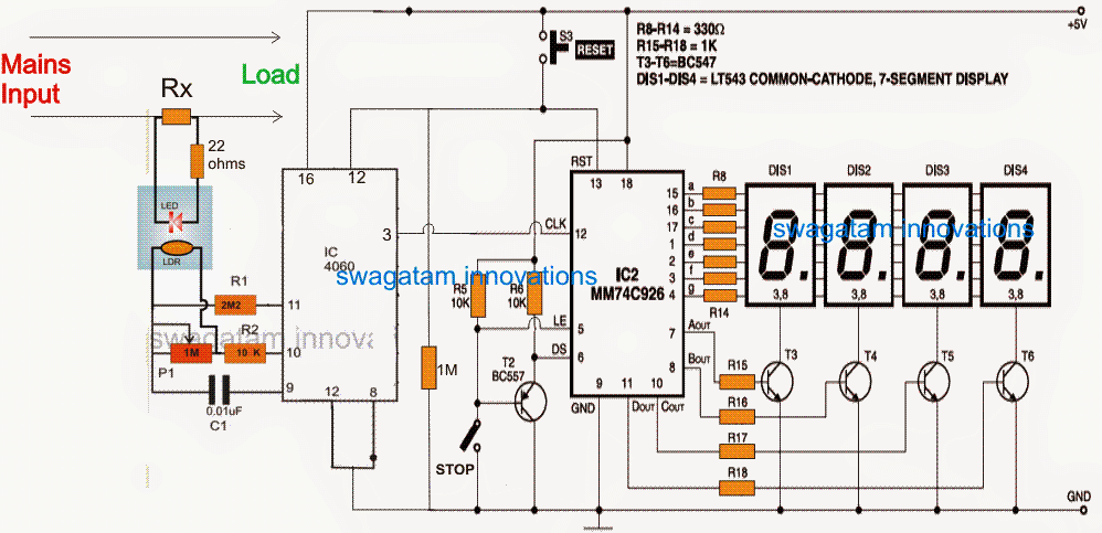
Referring to the proposed digital power meter circuit above, we can see the IC 4060 configured as a voltage to frequency converter, while the IC MM74C926 forms a frequency counter stage capable of counting upto 9999 pulses continuously through the connected 4nos of 7 segment common cathode displays.
The IC 4060 is actually a counter divider IC which is configured in a rather unusual way here for achieving the voltage to frequency conversion.
In the normal mode the preset P1 can be adjusted for increasing or decreasing the frequency generated by the IC at its pin#3, however as can be seen in the diagram, an LDR/LED arrangement is connected parallel with the P1 preset, such that the LDR effectively changes the P1 value in response to the illumination intensity of the concealed LED integrated with the LDR.
Determining LED Brightness
The LED brightness is controlled or determined by the current flowing through Rx. The current through Rx is directly proportional to the wattage consumed by the attached load. Therefore if the load consumption increases the current through Rx increases, which in turn increases the pin#3 frequency of the the IC.
Since the pin#3 of IC 4060 is attached with the clock input of the pulse counter circuit, the varying frequency equivalent to the load consumption is counted by this stage and is displayed over the connected 4 display modules.
The STOP switch can be switched ON anytime to freeze the display reading, may be during end of the day when the final reading is to be studied.
For resetting the display and begin the counting afresh, the given reset button can be pushed and released momentarily.
Calculating Limiting Resistor Rx
Rx may be calculated as per the given.
Rx = LED forward voltage drop / Maximum allowable wattage for the load.
For example, if the LED Fwd voltage is 1.5V (for red LED), and the maximum allowable wattage is 2000 watts at 220V AC, then the calculations can be implemented as follows:
2000/220 = 9 amps
Rx = 1.5/9 = 0.16 ohms
resistor wattage = 1.5 x 9 = 13.5 or 15watts approximately
P12 can be used for adjusting or fine tuning the range of the watt meter suitably.
The entire circuit could be powered from a 5V supply, which could be acquired from a cell phone charger unit and after regulating through a 7805 IC.
If the 4060 converter stage looks a little crude to you, you can opt for an alternative voltage to frequency converter circuit, for getting a more professional response from the discussed power meter circuit.

Questions & Answers
ok first of your radest dude i been learning electronics for long time and some times find what i read becomes quite confusing do to i just quite understanding how components design concepts coeinside to gather i consider my self quite able to repair and construct my own electronics but i also need just little help say like i need a sata to usb data line can not buy as i am poor man and disabled i made and designing new type of adjustable multi powersuppy i have the lame old atx ps took made easy lm317 reg.adj. i need detailed instructing on using old parts from stuff to builds my own sata to usb like all parts how put data cable to geather and use a atx power scores
Hello, I am not sure what you mean by sata to USB, or may be I have no idea about it!
So if I remove lower pin 12 I will connect pin 8 to ground right? Also how can I connect this LED/LDR arrangement?
yes that’s right! LEd and LDR must be built inside a small light proof enclosure, both facing each other inside the enclosure.
Mr Swagatam, IC 4060 has two pin 12 in this diagram, is it a mistake? Please clarify me. Thanks
Thanks Dominic, yes the lower pin12 is a mistake, please remove it, it’s wrongly shown. The upper pin12 is the correct one.
Dear RX has approximately 15 W this big waste and heat source is there any better solution to fix this problem??
BR
You can use an op amp amplifier across Rx, then Rx can be reduced to much smaller values.
Hi Swag,
I click on the circuit but I get no magnification.
Best Regards,
Nélio Abreu
Hi Nelio, It is because the image is already in its enlarged form. You can right click on it and open it in a new tab, and see if that helps to produce a better view?
Hello sir, would you plz give me a clear circuit diagram of this energy meter, I cannot understand something from the diagram provided abov
MI Rajput, please click on the schematic to enlarge it and get the clear picture
Icmm74c926 is not available in our area. It has any alternative?
you can try it online…..I am not sure about any equivalent of this IC
hi great SWAGATAM now i have small keypad digital meter which shows electricity units and when it goes to zero i have to buy electricity on my phone ( simply say electricity airtime using mobile money) or payway, do you have any idea how i can hack this meter to make it run slowly when ever i power on my gadgets or even make it freeze for some time when me am using my gadgets , doing this because i spend much on electricity. please help me if you any idea about how to hack the meter and make it run too slowly whenever i power on lights and other gadgets , thanks
Hi Davis, sorry I do not have any knowledge regarding hacking a device, that's beyond my level of expertise!
why did you upload the usless meterials for us? check the pin no.12 of IC CD4060….. how to work this?eally waste…..
do you understand electronics? do you know English?
pin12 is correctly configured.
Sir the power meter above use a 4 pieces of a 7segment displày.
yes that's right….