When a DC to AC inverter is operated through a solar panel, it is called a solar inverter. The solar panel power is either directly used for operating the inverter or it's used for charging the inverter battery. In both the case the inverter works without depending on mains utility grid power.
Designing a solar inverter circuit essentially requires two parameters to be configured correctly, namely the inverter circuit and the solar panel specs. The following tutorial explains the details thoroughly.
Building a Solar Inverter
If you are interested to build your own solar inverter then you ought to have a thorough knowledge of inverter or converter circuits, and regarding how to select solar panels correctly.
There are two options to go about from here: If you think making an inverter is much complex, in that case you could prefer buying a ready made inverter which are plentifully available today in all sorts of shapes, sizes and specs, and then simply learn only about solar panels for the required integration/installation.
The other option is to learn both the counterparts and then enjoy building your own DIY solar inverter step wise.
In either case learning about solar panel becomes the crucial part of the proceedings, so let's first learn about this important device.
Solar Panel Specification
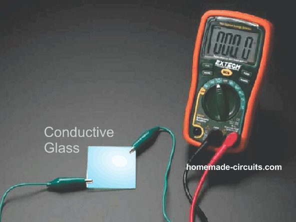
A solar panel is nothing but a form of power supply which produces a pure DC.
Since this DC is dependent on the intensity of the sun rays, the output is normally inconsistent and varies with the sun light position and climatic conditions.
Although solar panel is also a form of power supply, it significantly differs from our usual home power supplies using transformers or SMPS. The difference being in the current and voltage specs between these two variants.
Our home DC power supplies are rated to produce higher amounts of current, and with voltages perfectly suiting a given load or application.
For example a mobile charger may be equipped to produce 5V at 1 amp for charging a smart phone, here the 1 amp is amply high and the 5V is perfectly compatible, making things extremely efficient for the application need.
Whereas a solar panel may be just the opposite, it usually lacks current and may be rated to produce much higher voltages, which could be hugely unsuitable for general DC loads such as a 12V battery inverter, mobile charger etc.
This aspect makes designing a solar inverter a little difficult and requires some calculations and thinking in order to obtain a technically correct and efficient system.
Selecting the Right Solar Panel
For selecting the right solar panel, the basic thing to consider is that the average solar wattage must not be less than average load wattage consumption.
Let's say a 12V battery needs to be charged at 10amp rate, then the solar panel must be rated to provide a minimum of 12 x 10 = 120 watts at any instant as long as there's a reasonable amount of sun shine.
Since generally it is difficult to find solar panels having lower voltage and higher current specifications, we have to move on with what is readily accessible in the market (with high voltage, low current specs), and then dimesnsion the conditions accordingly.
For example if your load requirement is say 12V, 10 amps, and you are unable to get a solar panel with this specs, you may be forced to opt for an incompatible match such as a 48V, 3 amp solar panel which looks much feasible to procure.
Here the panel provides us with voltage advantage, but current disadvantage.
Therefore, you cannot connect a 48V/3amp panel directly with your 12V 10 amp load (such as a 12V 100 AH battery) because doing this would force the panel voltage to drop to 12V, at 3 amps making things very inefficient.
It would mean paying for a 48 x 3 = 144 watt panel and in return getting 12 x 3 = 36 watt output...that's not good.
In order to ensure an optimal efficiency we would need to exploit the voltage advantage of the panel and convert it into a equivalent current for our "incompatible" load.
This can be very easily done using a buck converter.
You will Need a Buck-Converter for Making a Solar Inverter
A buck converter will effectively convert the excess voltage from your solar panel into an equivalent amount of current (amps) ensuring an optimal output/input = 1 ratio.
There are a few aspects here which needs to be considered. If you are intending to charge a lower voltage rated battery for later use with an inveter then a buck converter would suit your application.
However if you intend to use the inverter with the solar panel output during daytime simultaneously while its generating power, then a buck converter would not be essential, rather you could connect the inverter directly with the panel. We will discuss both these options separately.
For the first case where you might need to charge a battery for later use with an inverter especially when the battery voltage is much lower than the panel voltage, then a buck converter could be imperative.
I have already discussed a few buck converter related articles and I have derived the final equations which can be directly implemented while designing a buck conveter for a solar inverter application, you may go through the following two articles for getting an easy understanding of the concept.
Calculating Voltage, Current in a Buck Inductor
After reading the above posts you might have roughly understood regarding how to implement a buck converter while designing a solar inverter circuit.
If you are not comfortable with formulas and calculations, the following practical approach could be employed for obtaining the most favorable buck converter design output for your solar panel:
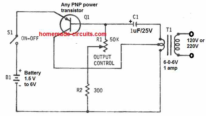
Simplest Buck-Converter Circuit
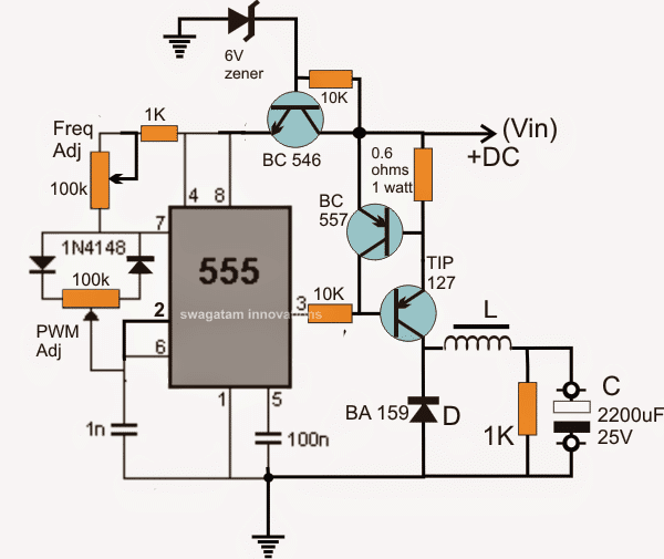
The above diagram shows a simple IC 555 based buck converter circuit.
We can see two pots, the upper pot optimizes the buck frequency, and the lower pot optimizes the PWM, both these adjustments could be tweaked for getting an optimum response across C.
The BC557 transistor and the 0.6 ohm resistor forms a current limiter for safeguarding the TIP127 (driver transistor) from over current during the adjustment process, later this resistance value could be adjusted for higher current outputs along with a higher rated driver transistor.
Selecting the inductor could be tricky.....
1) The frequency may be related to the inductor diameter, lower diameter will call for higher frequency and vice versa,
2) Number of turns will affect the output voltage and also the output current and this parameter would be related to the PWM adjustments.
3) The thickness of the wire would determine the current limit for the output, all these will need to be optimized by some trial and error.
As a rule of thumb, start with a 1/2 inch diameter and number of turns equal to the supply voltage....use ferrite as the core, and after this you can begin the above suggested optimization process.
This takes care of the buck converter which can be used with a given higher voltage / low current solar panel to obtain an equivalently optimized lower voltage / higher current output, as per the load specs, satisfying the equation:
(o/p watt) divided by (i/p watt) = Close to 1
If the above buck converter optimization looks difficult, you could probably go for the following tested PWM solar charger buck converter circuit option:
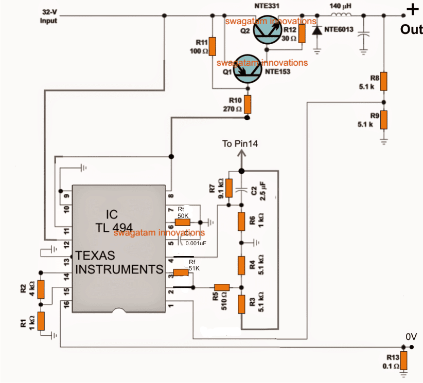
Here the R8, R9 can be tweaked for adjusting the output voltage, and the R13 for optimizing the current output.
After building and configuring the buck converter with an appropriate solar panel, a perfectly optimized output could be expected for charging a given battery.
Now, since the above converters are not facilitated with a full charge cut off, an external opamp based cut-off circuit might be additionally required for enabling a fully automatic charging feature as shown below.
Adding a Full Charge Cut-off to the Buck Converter Output
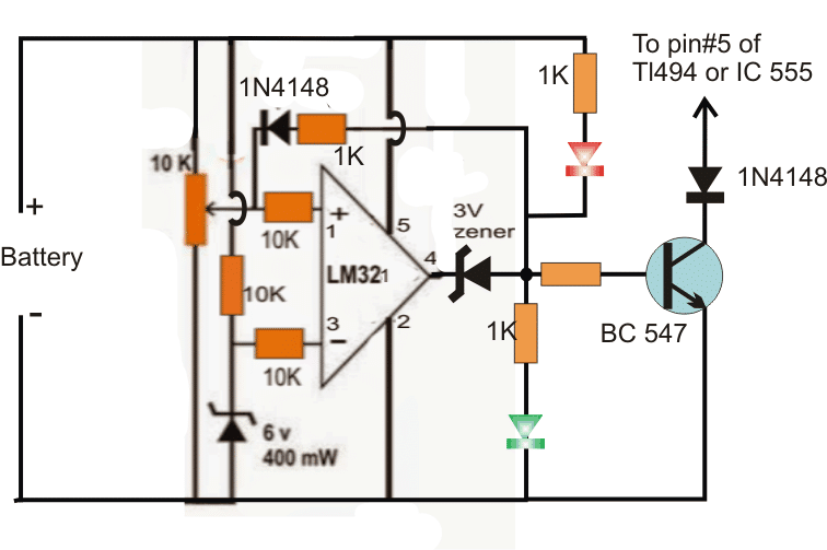
- The shown simple full charge cut-off circuit could be added with any of the buck converters for ensuring that the battery is never over charged once it reaches the specified full charge level.
- The above buck converter design will allow you to get a reasonably efficient and optimal charging for the connected battery.
- Although this buck converter would provide good results, the efficiency could deteriorate as the sun went down.
- To tackle this, one could think of employing a MPPT charger circuit for acquiring the most optimal output from the buckcircuit.
- So a Buck circuit in conjunction with a self optimizing MPPT circuit could help in churning out the maximum from the available sun light.
- I have already explained a related post in one of my previous posts, the same could be applied while a solar inverter circuit design
Solar Inverter without a Buck Converter or MPPT
In the previous section I have explained to design a solar inverter using a buck converter for inverters with lower battery voltage rating than the panel and which are intended to be operated during night time, using the same battery which was charged during the day time.
This conversely means that if the battery voltage is upgraded somehow to match approximately with that of the panel voltage then a buck converter could be avoided.
This may be also true for an inverter which may be intended to be operated LIVE during daytime, meaning simultaneously while the panel is generating electricity from sunlight.
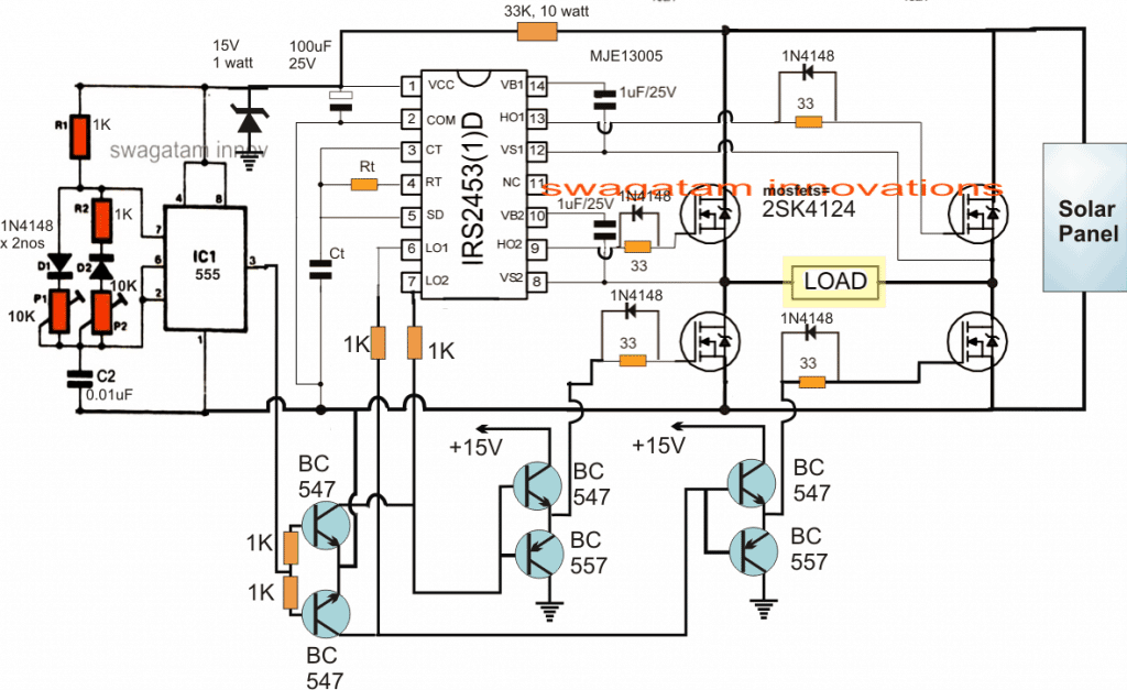
For simultaneous day time operation, the suitably designed inverter could be directly configured with a calculated solar panel having the correct specifications as shown below.
Again we must make sure that the average wattage of the panel is higher than the maximum required wattage consumption of the inverter load.
Let's say we have an inverter rated to work with a 200 watt load, then the panel must be rated at 250 watts for a consistent response.
Therefore the panel could be a 60V, 5 amp rated, and the inverter could be rated at around 48V, 4amp, as demonstrated in the following diagram:
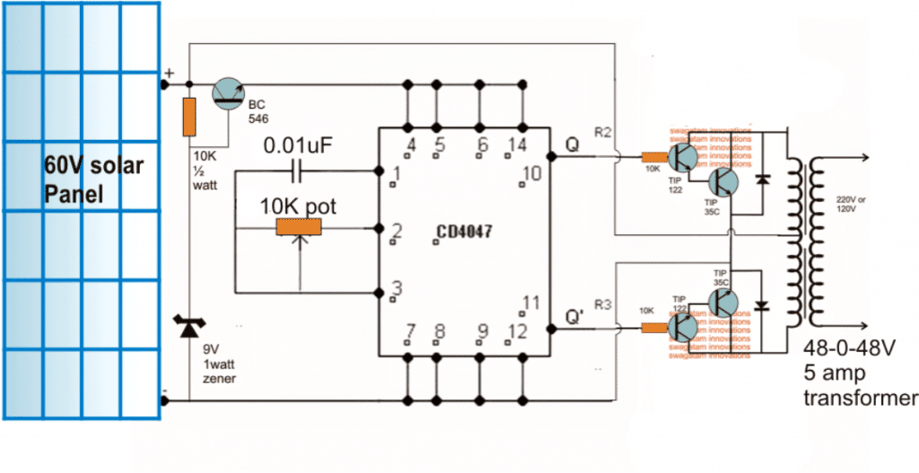
In this solar inverter, the panel can be seen directly attached with the inverter circuit and the inverter is able to produce the required power as long as the sun rays are optimally incident on the panel.
The inverter would keep running at a reasonably good power output rate for so long as the panel produces voltage above 45V...... that is 60V at the peak and down to 45V probably during afternoon.
From the above shown 48V inverter circuit it is evident that a solar inverter design does not need to be too crucial with its features and specifications.
You can connect any form of inverter with any solar panel for getting the required results.
It implies that you can select any inverter circuit from the list, and configure it with a procured solar panel, and begin reaping free electricity at will.
The only crucial but easy to implement parameters are the voltage and the current specifications of the inverter and the solar panel which must not differ by much, as explained in our earlier discussion.
Modified Square wave Solar Inverter Circuit
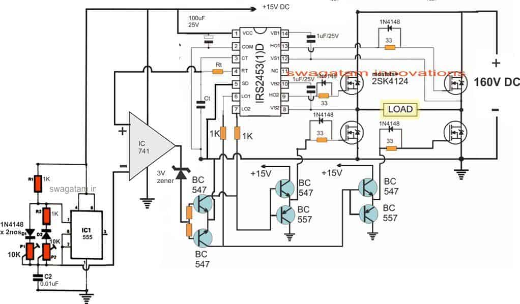
All the designs which are so far discussed are intended to produce a squarewave output, however for some application a square wave could be undesirable and might require an enhanced waveform equivalent to a modified sine wave. For such requirements a PWM operated circuit could be implemented as shown below:
Note: The SD pin#5 is mistakenly shown connected with Ct, please make sure to connect it with ground line and not with Ct.
The above solar inverter circuit using using PWM sine wave can be studied elaborately in the article titled 1.5 ton AC solar inverter circuit
From the above tutorial it is now clear that designing a solar inverter is after all not so difficult and could be efficiently implemented if you are equipped with some basic knowledge of electronic concepts such as buck converts, solar panel and inverters.
A sinewave version of the above can be seen in the following diagram, which works using an SPWM chopping for the low side mosfets :
Still confused? Do not hesitate to use the comment box for expressing your valuable thoughts.
Remember, a solar inverter is as easy as hooking up any standard inverter to a solar panel, ensuring that the solar panel voltage is only slightly higher than the inverter operating DC specs.
If you want any customized solar inverter circuit of your choice designed by me here, please feel free to put the request through the below comments, I will try to fulfill it as soon as possible.
Conclusion
Designing a solar inverter can be a complex process that involves a good understanding of electronics, power systems, and solar energy. Here are some general steps to consider when designing a solar inverter:
- Determine the load requirements: The first step in designing a solar inverter is to determine the load requirements. This will include the power requirements of the load, as well as the type of load (i.e., resistive, inductive, or capacitive).
- Determine the solar panel specifications: The second step is to determine the specifications of the solar panels that will be used with the inverter. This will include the voltage and current output of the solar panels, as well as their maximum power point (MPP) voltage and current.
- Choose the inverter topology: The next step is to choose the inverter topology that will be used. There are several different types of inverter topologies, including transformer-based and transformerless designs.
- Select the components: Once the inverter topology has been chosen, the next step is to select the components that will be used in the inverter. This will include selecting the power semiconductors (i.e., MOSFETs, IGBTs), capacitors, inductors, and resistors.
- Design the control circuit: The control circuit is an important component of the inverter, as it regulates the voltage and current output of the inverter. The control circuit will include a microcontroller, voltage and current sensors, and a feedback loop.
- Build and test the prototype: Once the design is complete, it is important to build and test a prototype of the inverter to ensure that it meets the specifications and performance requirements.
It is important to note that designing a solar inverter can be a complex process that requires a good understanding of electronics and power systems. It may be helpful to consult with a qualified engineer or to use a pre-designed inverter kit or module.


Comments
Good morning everyone am in need of a good 12v to 220v 1000w transformerless inverter please can any one send it to me because i know that god have bless people with wisdom in this page i need it urgently please sir and ma any one please
Samson, you can try this design:
https://www.homemade-circuits.com/arduino-h-bridge-sine-wave-inverter-circuit/
Hi, Mr Swagatam. My department is trying to build a 300 to 500 watts inverter that’ll be powered by a solar panel and would also include a battery option with charging efficiency. I would really appreciate your help on this. Also, the inverter would be a pure sine wave inverter.
Hi Shogbesan,
I can certainly help. Can you please provide your preferred solar panel specifications in terms of voltage, current, or wattage?
Dear Swagatam, I am following your valuable Articles from recently. Thank you very much and appreciate your support for all of us eager to gain knowledge in electronics circuits. Any chance of sharing a Pure sinewave Inverter Circuit for a 4 KW solar system please? Wasantha Karynanayake.
Thank you Wasantha, I am glad you found my articles useful. To make a sine wave solar inverter, you will first have to build a sine wave inverter, then upgrade the mosfets and the transformer to handle 4kw, and then connect this inverter with an appropriately rated solar panel. To design a sine wave inverter you can refer to the following article, let me know if you have any further questions.
https://www.homemade-circuits.com/designing-a-sine-wave-inverter-circuit-from-the-scratch-tutorial/
Please send me full sine wave different wattage inverter directly to solar. out put volt 220 but easy and clear circuit diagram. Thanks???? sir
Hi Muhammad, you can follow the details provided in the following article, and build a basic sine inverter first, then I will guide you with the solar panel integration process. Let me know if you need any further help!
https://www.homemade-circuits.com/designing-a-sine-wave-inverter-circuit-from-the-scratch-tutorial/
Sir direct solar inverter circuit diagram send me different watts pure sine wave
could a solarpanel array being used with supercapacitors to offset the big start currents from fridges or aircons so that my surface area of solarpanels can be reduced?
Yes, that may be feasible using a large bank of super capacitors.
we want to design npc inverter(0.5 kw) for this we have 320 watt 3 solar panel plate please call 9610444483
Sorry, telephonic talk may not be possible, you can ask your questions here, I will be glad to help!
okey thank you sir i will come up with similar IC
OK, no problem!
if i came up with a different ic could you make a circuit for me
I can try to design it for you if the IC specifications are identical.
if couldnt find please suggest an alternative ic thats available with circuit
You can try searching for the phrase “Full bridge Driver IC”….you may find some good related options.
and also i couldnt find the ic irs2453D near me can you provide a trust full sorce or link where i can purchase the IC
Sorry, unfortunately I do not know any trusted site from where you can purchase this IC.
a doubt there it is showing 160v Dc on the input of sine version (in the above diagram) what is the output at the load.and can you give the range of input that can be fed in to the input as it is a solar panel
In the following diagram, the load side AC will be also 160V, because the output will be square wave so its RMS will be same as the input DC.
https://www.homemade-circuits.com/wp-content/uploads/2017/10/3000-watts.jpg
The range will solely depend on the rating of the MOSFETs.
is there a boost circuit that has input solar panel and constant dc output voltage
You can try the first circuit from the following article:
https://www.homemade-circuits.com/12v-car-laptop-charger-circuit-using/
hi sir thanks for the valuble information ,could you help me in designing a inverter.
i need solar as input which is DC right and i need to step up to high voltage DC then convert it in to AC voltage 230V can you provide me with a Circuit please replay as soon as possible ,please
my whatsapp no:9747172174
Thank you Jyothikrishnan,
Please specify the maximum power of the load or the wattage of the load that you intend to connect with the inverter. I will try to help!
load is a 1HP motor take approx 800W
If you use a transformer then it will require a huge transformer, so instead of transformer I would recommend using high voltage panels.
The solar panel must be rated at around 240V or 260V and 3 amps.
The inverter circuit can be a full bridge inverter as explained in the FIRST diagram from the following article.
https://www.homemade-circuits.com/simplest-full-bridge-inverter-circuit/
However, in this diagram, IRF540 mosfets cannot be used, instead you may have to use 400 V mosfets such as IRF740
You can easily find similar diagrams which are newer, through the relevant datasheets.
i wanted to use a boost converter for stepping up to 240vDc and then to use this full bridge inverter can we do that then i need proper boost converter to include with this full bridge inverter
I don’t have an efficient 220V boost converter circuit with me at the moment. If I find one I will surely let you know.
okey please find one it will be a lot of help
Hello! Thank you for this excellent resource. I am building a 6 inverter off grid system tied to utility for backup battery charging. There is a lot of confusion in the community regarding inverters that bond neutral and earth ground together when in battery mode. Some inverters like the Victron cover when to remove the NEG bond, but others like my EG4 brand do not. I am very concerned about safety as well as equipment protection. If my utility supply panel is NEG bonded and my load panel is not bonded, but tied back to my supply panel, is there any good reason the inverter should connect neutral to earth ground under any mode? Same question applies to gas generator where the plug ties directly into either panel, the neutral and earth grounds will provide protection back to the generator without the generator needing a NEG bond.
Thank you very much for your expertise and explanations.
-Jay
Hi, thanks for your question, however I don’t seem to have sufficient information regarding how an inverter is supposed to be configured with the utility ground and neutral. The bonding is basically to ensure that the circuit breaker is able to respond and trip in case a relatively low current ground fault occurs across a load. For utility wiring the neutral-ground is normally bonded on the main panel, but I am not sure how an inverter needs to handle this wiring.
Great site! Thanks.
I have a grid-tied system with a string inverter. I recently got a “driver circuit failure” and have been trying to figure out what it means. The system is currently down because the inverter will not operate. Could it be a power supply issue, or a bad connection inside the inverter? The inverter is about 10 years old, but the error does not indicate a capacitor failure.
Any thoughts? Is it repairable?
Thank you, an glad you liked this site! Sorry, it can be difficult to judge the fault because all inverters have their own specific design layout. The fault can be confirmed only through a practical checking.
OK, no problem Asen,
I will check your email and if it is possible for me to solve the problem I will let you know.
Hi Sir Swagatam,
It seems that inverter we have discussed here is not suitable for aim I chase.
Basically I need schema of resonance half-bridge inverter which can convert 400V DC to 220V AC.
On your mail I sent you small diagram.
When you have free time please help me on that?
BR
Asen
Hi Sir Swagatam,
I will follow the link you have provided me and update you.
One more question. The output voltage is equal to the input one and if yes how we can set output to 220V?
BR
Asen
Hi Sir Swagatam,
I`ve made video where you can see output form and frequency from 741 at pin6
In shorts we have 50hz and 50khz on both inputs and 50hz on output.
Let me know if it is OK ?
BR
Asen
Hi Sir Swagatam,
I`ve bought items for original schematic and will follow it.
You have a new video with output across C2 on 555 taimer.
Actually I took it from ground and pin2 on IC741.
Let me know if pin2 of 741 is the right minus input from 555 and what are the next steps?
BR
Asen
Hi Sir Swagatam,
I`ve made new video.
Arcos Ct we have again 50Hz triangle not twice.
Also amplitude (peak to peak) is about 5.5V . Multimeter says 7.5V DC
Probably something is not good?
BR
Asen
Thank you Asen,
I checked the video and your assembly, it looks great, however I would have wanted to see a load connected between the mosfets to see if the inverter IC was actually handling the load correctly. If you could do this then the full bridge inverter section will be confirmed.
Now the next step would be to check the waveform across the Ct capacitor of the full bridge IC. It should be triangular waves at a frequency that’s perhaps two times the frequency of the output. Check the amplitude, it should be almost equal to the Vcc voltage.
After this check the triangular waves from the IC 555 across C2.
Sure, no problem….I think the output voltage RMS can be adjusted by reducing the amplitude of the slow triangle waves.
Hi Asen,
The 741 input will compare the fast and slow triangle waves at its inputs and generate an SPWM at the output, but it is not happening in your case as per the scope results.
It is a very standard process of getting SPWM. Normally we feed a sine wave instead of the slow triangle wave, but since we do not have a slow sine wave source therefore a slow triangle wave should also work fine.
Please check why you are not getting an SPWM.
The process is explained in this post:
https://www.homemade-circuits.com/how-to-generate-sinewave-pwm/
Thank you Asen.
I checked the video, and the waveform at pin#2 of the IC 555 looks good triangle waves….however make sure the frequency is at least 300 Hz because the triangle waves from the IC 555 is supposed to serve as the high frequency triangle wave on the (-) pin of the 741.
Yes, pin#2/6 will give you the required triangle waves from the IC 555 circuit.
After this you can integrate the two triangle waves with the inputs of the 741 op amp and the check whether or not the output of the 741 is generating the intended SPWM waveform.
Thank you Asen,
The triangular waves look good in the video, and the 7.5V is also fine….it will be quite enough to trigger the op amp response.
However, I am little confused regarding the 50 Hz frequency, I hope it is correct….the final results can be confirmed only once the SPWM section is built and implemented.
You can now proceed to check the triangular waveform across C2 of 555.
You can use the following design for the 555 pwm section, it looks easier than the actual circuit diagram
https://www.homemade-circuits.com/wp-content/uploads/2019/08/pwm-IC-555.png
Hi Sir Swagatam,
I`ve made and tested only basic schema.
Seems ok.
On your mail I`ve send you URL link for video I took.
Let me know your comments after that?
BR
Asen
Yes, that’s correct, I am referring to this basic circuit. You can confirm the frequency using an oscilloscope or by using a frequency meter across gate/source of the low-side mosfet.
Hi Sir Swagatam,
You mean to run initially below schematic?
https://www.homemade-circuits.com/wp-content/uploads/2021/08/full-bridge-inverter-compressed.jpg
If yes, will try it with already setup Ct/Rt combination for 50hz (Ct is 1mF Rt is 13Kom)
BR
Asen