In this post I have explained a circuit which can be used for controlling 1 to 8 appliances with a single RF 433MHz remote control handset. Now you can control fans, lights ACs, oven etc within a range of 50 meters with the same remote.
In a few of my earlier posts I have comprehensively discussed regarding these versatile and outstanding remote control modules, for reference you may want to go through the following links:
Simple RF Remote Control Circuit without Microcontroller ...
Make a Hi-End RF Remote Control Circuit | Electronic Circuit Projects
RF Remote Control Encoder and Decoder Chip Pinouts Explained ...
Main Features of 433MHz RF Remote Module
The main features of these 433MHz remote modules are:
1) These are available with different ranges, from a single channel to as many as 8 channels, which allows the user to use 8 different appliances from a single receiver unit.
2) The technology used for transmitting the RF waves are extremely sophisticated which prevents the transmitted data from getting hacked.
3) The distance of transmission is also diverse, ranging from 50 meters to 5 kms.
4) Fully customizable "address pins" which enables us to use different remote control handsets with a single receiver unit or vice versa
Although it provides us with the facility to control 8 appliances from a single RF module, as discussed in the feature no#1 above, this isn't entirely convenient because since all the 8 relays are fixed in the given receiver board could mean a lot of wiring to be done for different appliances situated at different corners of the house.
This slight inefficiency accompanied in the system compels us to think of some alternative method which would allow us to employ individual single relay modules with the desired appliances and then toggle these individual modules through a single remote handset. This option looks much hassle-free as no extra wiring is required for the installations.
Yes, that's what we would be trying to implement by exploiting feature no#4 by customizing the address pinouts of the transmitter module as well as the associated various receiver modules.
Before jumping into the circuit design it would important for us to discuss how these address pins of the transmitter/receiver are related and maybe customized for specific applications.
How Address Pins Function
If you notice the decoder chip of the transmitter module and the encoder chip of the receiver module you will find that both these ICs include 10 address pins (A0 to A9). These address pins are directly compatible with each other, meaning configuration of the transmitter and the receiver address pins should be exactly similar in order to make them respond with each other.
For example suppose if only A0 address pin of the transmitter circuit is connected with ground then the only A0 of the receiver must be connected to ground for enabling the two counterparts to "talk" with each other.
In this proposed article where we are discussing how to control 8 appliances with a single remote control we take the advantage of the above explained "address pin" feature and configure 8 different receiver modules with a single transmitter remote handset.
The following example circuit illustrates the address pin configuration of the relevant Tx and Rx modules. Here we have employed a 4 channel remote module, however a single channel module could also be employed for getting the same results, just by modifying the indicated address pins of the units.
The Receiver Circuit
The following image shows the basic configuration of the receiver module. It shows the remote control application set up for one of the 8 appliances. Similarly, 7 more receiver modules need to built for enabling the control of the associated relevant appliances.
For all the 8 units only the address pins need to be differently configured by simply changing the pin connections with ground, meaning if A0 is connected to ground for the 1st module, then A1 needs to be connected with ground for the 2nd module, A2 for the third module and so on.
Rx Schematic
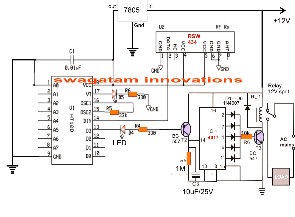
The IC 4017 section forms the flip flop circuit which ensures latching up of the load in ON and OFF conditions alternately, in response to the remote button press.
The Transmitter Circuit
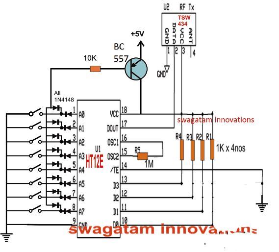
The following image shows the single remote control transmitter for the 8 separate receiver units as explained above.
Here pressing only the A0 switch activates the above shown receiver unit, since the A0 in the above design is connected with ground, therefore when A0 switch grounds its own A0 pin, both units "shake hands" and the signal is processed for toggling the appliance.
Similarly, switches connected across A1 toA7 can be made compatible with the remaining 7 receiver units for enabling the ON/OFF control of the attached 7 appliances located across different premises.
The diode network associated with the below shown transmitter unit makes sure that the BC557 activates and simultaneously powers the circuit only whenever the relevant switches are pressed, and otherwise the transmitter circuit remains completely switched OFF...this feature allows the battery to last for a very long time.
Tx Schematic
If you any further questions regarding how to control 8 appliances or multiple appliance with single remote, please feel free to ask them through your valuable comments.


Discussion & Solutions
Hello ,
I am making astronomical timer using atmega 32
Here is a pro lem with memory . I set the coordinate in system it store in memory , if i switch On/Off the system some time interval ( 2-3 Sec. ) Tjen memory ok but if on /off system very quickly again or again then coordinate reset ( 00.0000).
Plz tell me what is tje problem in circuit.
Hi, My microcontroller knowledge is not good, so I cannot solve your problem. Sorry about that.
Ok Thanks
Hello sir , i am a viewer of swagatam since 15 years , i faced a problem with rf 434 amhz.
If a single Transmitter is transmitting the data in case all car centeral lock remote does not work which is in range of transmitting transmitter.
One transmitter jammed all the transmitter .
Please tell me What is the solution .
Thank you so much Prashant.
As you will understand, such problems cannot be judged without checking the circuit practically. So without practically checking the situation it can be impossible to troubleshoot the problem. I think you should consult an automotive technician in your area for solving this issue.
Thank you for your reply but it this is not only my problem if you check any RF 434 or RF 315 Mhz Transmitter module then found every module have this problem .
You can test at your end. And viewer can test.
If one receiver transmeet data same time other transmitter can’t work in range of transmitting module .
I have so far tested only a single pair of these transmitter/receiver units, so I am not sure about this issue. Try adjusting the antenna wire or connect a 12 inch long flexible wire to the antennas of each receiver.
Sir thanks for your site and care,pls I need complete circuit of 4 channel remote control to turn on and off my 4 different home appliances any time I need them
Sir thanks a lot for this article. I have a question: if I press two or more switch at the time, the receivers go on/off simultaneously or there is a sort of priority?
Thank you again.
Hi Filippo, the receivers will switch simultaneously when more than one button is pressed.
Obinna, the schematic for 4 channel remote is already explained in the above article…..you just have to configure the pin#10, 11, 12, 13 accordingly.
Sir am a beginner in electronics so what I saw in that diagram is one relay and I need 4 relays as 4 channel controller so please where can I fix the other three relays
Obinna, you will have to build the following circuit, and connect the A, B, C, D points with the 4 separate 4017 IC flip flop circuits.
https://www.homemade-circuits.com/simple-100-meter-rf-module-remote/
Sir please all the ic in those circuit are they already programmed or should I be the one to program it myself
They are all pre-programmed, you just need to configure the pins as per the shown diagrams.
I will need the diagram
why is pin 13 (D3) grounded and 10,11, 12 not, in the Tx circuit?
Thanks for pointing it out, I have corrected the mistake.
Thank you for this correction????
Actually, the previous diagram was correct 🙂
I just forgot that pin#13 was deliberately grounded, as it would be normally implemented when a switch is used between pin#13 and ground.
so when pin#13 is grounded and pin#1 is also momentarily grounded via switch , there is output on pin#13 on the Rx and switches on the relay permanently , and will be turned off when pin#1 on Tx is
grounded again; is this conclusion right? if not, how could this be done in anther way??
CLEAR, THANK YOU SIR!
Glad it helped!
A0 to A7 work like compatible ON/OFF switches for switching the Rx load ON/OFf. Pin13 of Tx corresponds to pin13 of the RX, so pin13 of Tx must be connected to ground for enabling the generation the required Rf signal at the pin13 of the Rx.
Please Sir are the switch momentary type?
Please I needed your help. I wanted to use the above design to control fan regulator for switching 5 level speeds of a fan.
Lawal, switches are not momentary, and this particular circuit cannot be used for 5 step fan dimming.
Please Sir could you provide me with a design using rf transmitter and receiver to control 5 level speeds of a fan?
We can perhaps modify the last circuit from the following article. Please build the last design without the IR sensor, and manually confirm the response of the circuit. If it works for you, then we can configure the RF remote with the pin#14 of the IC 4017 accordingly:
Remote Controlled Ceiling Fan Regulator Circuit
Please Sir,does the tx used momentary push button switch?
How to make it use momentary push button switch to enable sudden change of transmission as in remote control button
Lawal, the switches shown across the address pins are all SPDT switches, they are not push buttons, you can use different combinations of those switches to switch specific sets of receivers and loads
Hi Swag,
Is there a chip that has more than 8 channels?
Say, 12, 16, or more?
best regards.
Hi Nelio, yes, it seems they are available on amazon.
Hello, how can I control 8 DC motors with it?
You will have to make 8 of the receiver units for controlling 8 motors separately
Please Sir,will you attach the remaining modules at the output pins 12,11,and 10 of the Same Decoder IC HT12D for controlling 4 appliances,while the remaining 4 appliances control modules being attached to another Same HT 12D output pins 13,12,11 and 10 to complete the total modules for the full 8 appliances ?
It will be identical to the pin13
Dear Swagatahm
I intend to connect this one circuit diagram to an eight dc motor? If possible how can it be rotated in reverse and forward? As well as how to control its speed? please answer
Dear Vinod, operating 8 motors with speed control and reverse forward cannot be done with this simple design
Hello Swag,
Here I am trying to implement this Project with little bit modifications which are I have to use one Tx and Rx. At Tx side when I press 1 switch at that time Rx side 1 relay on and same switch press again it should be off like that I used 4 switch and 4 relay. I have found some questions regarding this article,
1) May I 4 input switch at Tx side for control 4 relay at RX side?
2) What are the value of C3 Capacitor?
3) Can you share some video if you have for this simulation perform. I hope this works fine.
Hello Milan, yes you can use 4 channel Tx, Rx unit.
C3 can be any capacitor between 1uF/25V an 10uF/25V.
I do not have any video but as we all know that these Rf modules are highly reliable and will always work.
if two or more inputs are given at the same time the Receiver section will work properly ?
Thank you!.
No it won’t work properly