In this post I have explained how to increase or extend the range of an ordinary infra red or IR remote control through a 433MHz RF remote control system.
IR Range Extender Concept
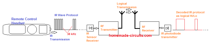
The idea of this circuit is to feed the IR data from an IR transmitter into the transmitter input of an RF module through an IR sensor, and transmit the data in air so that the distant RF receiver module is able to receive the data.
After receiving the data the RX would decode it and convert it back to IR based data, which could be used for triggering the relevant IR operated distant device.
Block Diagram
Parts You will Need to Build this Circuit
Transmitter Stage
433MHz or 315 MHz RF Encoder Modules, as shown in the following article, and assemble them as show:
How to wire RF Module circuits
All below shown Resistors are 1/4 wat t 5% CFR, unless otherwise specified
1M - 1no, 1 K - 4nos, 100ohms = 2nos,
Transistor BC557 = 1no
Capacitor 10uF/25V = 1no
Receiver Stage
433MHz or 315 MHz RF Decoder Modules, as shown in the above linked article, and to be assembled as show:
1K = 1no, 10K = 1no, 330ohms = 2nos, 33K = 1no
IR photodiode (any type) = 1no
Transistor = BC557
RED LED = 2nos
Capacitor -= 0.01uF
The IR to RF Range Extender Transmitter Circuit
The figure above shows the basic layout for the infrared remote control range extender transmitter circuit, wherein a 433MHz or a 315MHz RF encoder circuit can be seen built around the chips HT12E and TSW434, and we can also see an attached simple IR sensor circuit stage using TSOP730.
The IR sensor can be visualized at the extreme right side of the diagram with pinouts: Vs, Gnd, and O/p. The output pin is connected with the base of an PNP transistor, whose collector is integrated with one of the 4 input pinouts of the RF encoder IC HT12E.
Now, to enable transmitting of the IR data to a distant location to extend its range, the user has to point the IR rays on the sensor from a IR handset and press the relevant button of the IR handset remote.
As soon as the IR rays hit the TSOP sensor, it converts the data into its respective PWM format and feeds the same to the selected input pinouts of the HT12E encoder.
The encoder IC picks up the converter IR signals, encodes the data and forwards it to the adjoining TSW434 transmitter chip for allowing the transmission of the data into the air.
The signals travels through air until it finds the antenna of the corresponding RF decoder module using 433MHz or 315MHz as the operating frequency.
The Range Extender RF Decoder Receiver Circuit
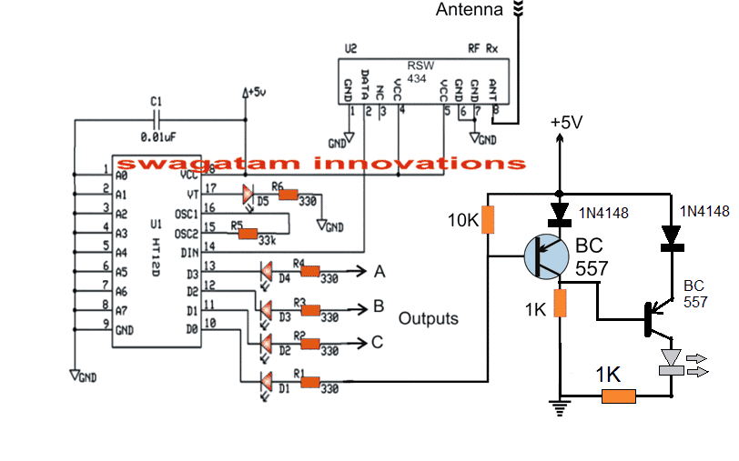
The circuit diagram shown above represents the IR data receiver circuit which receives the transmitted signal from the transmitter end and reverts the signals back to the IR mode for operating the IR device extended at this remote end.
Here the RF decoder module is built using HT12D IC and the receiver using RSW434 chip. The receiver chip picks up the transmitted IR to RF converted data, and sends it to the decoder IC, which completes the process by decoding the RF signals back to IR frequency.
This IR frequency is appropriately fed to an IR photo-diode driver circuit built using a PNP transistor and an IR photo-diode device, as shown at the extreme right side of the circuit.
The decoded RF to IR frequency is oscillated and transmitted by the photo-diode and applied on the device which is to be operated at the remote end.
The device hopefully responds to these RF decoded IR signals and functions as per the expected specification.
This concludes the IR range extender circuit using RF 433MHz modules, if you think I have missed something in the design or in the explanation please feel free to point them out through the comment box below.
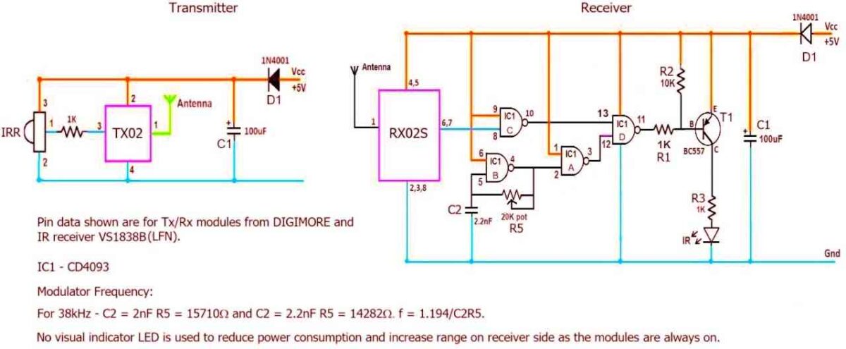
Another IR Remote Control Extender Circuit using Rx, Tx Modules
This schematic was graciously contributed by Mr. K. Ayyappan to benefit all the interested readers. We sincerely appreciate his valuable contribution.
Circuit Description
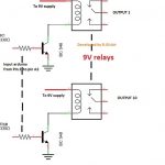
In this always on circuit the demodulated signal out of IR receiver is fed directly to the transmitter module TX02. At the receiver RX02S side, the on-air received signal is modulated with CD4093 marked IC1. IR LED driver can be an NPN(Emitter Follower configuration) or a PNP as shown. The resistor in series with IR LED controls the IR range.
This may be one of the simplest IR extenders with minimal component footprint. The Tx and Rx home made boards as per given schematic using a Veroboard KS 110, cut as required, have been tested for over a year. No performance reduction, components failure or spurious operations have been observed despite some issues as described below:
The IR LED remains on with lesser intensity when no signal is received. This is observed to be due to
1. The ASK Receiver is prone to noise pick-up from various sources like a passing motorbike's engine, fan or any other motor, TL, etc.
2. The free running modulator IC1 using CD4093 cannot be turned off when not required without increasing the complexity of the circuit via pin 6 of IC1 segment marked IC1 - B as an "enable" signal.
Other considerations:
1. T1 base current may be reduced using a higher value R1 to reduce IR LED no-signal intensity though it may not be possible to eliminate it totally.
2. Resistor R2 at IR LED driver T1 is not required at all and can be dispensed with.It does not serve the intended purpose due to factors listed above.
3. Components used were lying around in stock except for Tx/Rx modules. No calculations were done to arrive at values shown or selection.
Though the Rx module from DIGIMORE has a 434MHz oscillator, modules from other vendors having other oscillators do work. For e.g. an Rx module with 6.7458MHz crystal has been tested to be working properly.
Special mention: Thanks to Nuts & Volts Magazine for the modulator frequency calculation.


Questions & Answers
Tried HT12E/D circuit as given here though I had my reservations about them as mentioned earlier. It did not work.
I just used an LED at D0 of both encoder and decoder ends to see if they mimic each other. The demodulated output from IR receiver is fed directly to D0 of encoder and also after inverting using a NAND gate. The LED at HT12E blinks with slightly lower intensity on direct connection and brightly when used with a NAND gate as expected. But at HT12D decoder end the LED either remains on or off – static. And at times the LED at decoder end comes on on power up and stays so. Both HT12E/D operated on 9V battery via a 7805 regulator with appropriate filtering.
OK, thanks for your feedback, I will surely experiment it myself in my free time, and update the response here…
Hi,
Thank you for posting my schema. However please note that for an NPN driver, the C should at high side and E at R/LED side. This may sound obvious but for a newcomer this is essential. NPN tried was 2N2222A.
Thank you sincerely for your valuable efforts to enhance this design. I hope the readers will find the information helpful and take it into account as they proceed.
Additionally I have updated the circuit description based on the suggestions you shared in your email.
Hi, greetings. The IR extender as described here seems interesting. Has this been tested to be working? I have been using a simpler IR extender without HT12E/D for over a year now. I can mail the schematic if desired. But it has one glitch – the IR LED at receiver end remains pulsing thanks to the RF receiver picking all and sundry noise from other sources. With the receiver side remaining on 24Hrs all these days, I was expecting the IR LED performance to reduce or IR LED to perish but luckily it is still working. If the designs as given here using HT12E/D works it would do a lot of good perhaps to keep IR off when no addressed transmission is present. Using the not so easily available HT12A instead of HT12E would be an option but not tried so far. And I am not sure if HT12E is capable of handling pulsed inputs. Please let me know. Thank you.
Additional info: The IR Tx/Rx boards made on perforated project boards(6 x 3.5 cms) are encased in HDMI extender boxes which may contribute additional noise. Though the HDMI extender boxes have built in IR they did not support RC5/6 protocols.
Hi, the circuit is not yet tested by me….if you are using a photo diode or an IR LED, it can be enclosed inside an opaque tubing, open at the ends, then it can be blocked from spurious light sources and triggered only through legitimate IR sources.
HT12E can probably handle pulsed inputs if the frequency is in kHz.
You can send me the schematic at my email
homemadecircuits
@gmail.com
Hi, thank you for your prompt reply. I have already tried HT12E/D but with different values for HT12E/D oscillators but no go. I used readily availble Tx/Rx boards with HT12E/D and made changes accordingly. Please see the mail for the schematic of the one that I use.
The Rx side noise is due to ASK Rx picking up external noise probably due to built in AGC. I could verify this with Tx off and use a non-infra LED and an R at data out of Rx. I will try HT12E/D combo avoiding the pre-fab boards and revert.
I’m not convinced that HT12E/D are capable of handling IR as described in IR extender here. For e.g. RC5 has 14 bits and takes approx 25ms per frame. With 8 address bits 4 data bits how the 14 bits are expected to be sent to transmitter module is a big question. Besides HT12D is a latch type. They are suitable for one of two states ops only.
These E/D have been existing for years now but not one article mentions about its use in IR control of devices that has more than 4 ops and that too not an On/Off static state given that so many brilliant heads out in the world. So there’s nothing to revert with for use as an IR extender by me.
Thank you very much for your kind feedback, and for sending me the schematic; I have successfully received it. I have included it in the article above to ensure that other readers can benefit from your contribution. Your generosity is greatly appreciated!
Dear
i have seen one IR Remote Control in which IR led give too long range up to 50 to 60 feet with good degree.
i test many IR led like Osram, Everlight ,Merubeni & some other chinise also with same Remote but i am still less satiny. There is one golden filament type net on waffer shown inside it.
Some one say if we use Laser IR then it will possible.
Kindy suggest me what technology used inside for increase range of IR led ?
Laser beams can be used to drastically improve the response of IR LEDs. However for long range triggering IR LEDs are normally not good….you can try the TSOP type IR receivers for excellent range and distance:
https://www.homemade-circuits.com/how-to-connect-tsop1738-ir-sensor/
thanks
Hi,
How can I make IR Hidden Infrared Remote Extender Receiver Emitter Repeater System Kit at home
Can you provide the circuit diagram?
Sorry I don’t have this circuit diagram with me…
A similar concept is I have explained below:
How to Make a Light Communicator Circuit [using InfraRed]
Good afternoon
Why use encoder and decoder in the infrared extender circuit? Since I have already seen similar circuits, but I don’t know if it works, which only uses the tx / rx module to use in the extender circuit
Grateful for the attention
I will send you some of my activities in this field …… Thank you
sure!!
I am sorry that I wrote before your answer. You are absolutely right and your answer is the correct science …. Yes you know the discussion between the engineers and please accept the first apologies and secondly that you are on the path of explanation in the explanation I hope that future see your creativity in this effort …… Please accept my sincere thanks and appreciation to you.
No problems, I understand! Wish you all the best!
Even though I did not answer my comment, it was better to remember that the process does not send the information, but only send it to indicate 0 or 1 only as a key no more simple and is not suitable for sending information …… I now wish to note you as engineer to engineer colleague … My sincere greetings to you.
I have drawn a block diagram at the top, which shows how the system is supposed to work. The transmitter and receiver are only supposed to interpret the high and low from the remote.
Sir,
this design not operates at all and unacceptable , please if you could show us a video , …how much I tried but in vain
the signal from I R is pure digital and consist of many element of h,L signal simply ….I say at end is not true circuit please answer me ………I appreciate .
kadhim, electronics is all about understanding, and using our brain to solve an issue, right?
Here we are not sending any complex data, we are trying to send an ON/OFF switching signal to the remote device which may be an appliance.
And What is so complex about the TSOP device? It simply has carrier frequency of around 38 kHz which can be modulated as per our specific need. But here we are NOT modulating it, we are simply sending these 38 kHz through the RF modules. And since the 38 kHz is also an ON/OFF logic signals it should be accepted and transmitted by the remote controlled ICs. This is my understanding? If you have a better explanation then you can share it.
If possible I’ll try to create a video for it soon.
sir could I get some benefit from your advice if u agree to except me ?
You can ask your questions, I’ll try to help!
Swag,
I made this circuits but have some isdues; the txmr seems working good but the rxvr end led connected on pin10 is on & will off once the txmr switch on & the led connected pin 17 will on. It will blink according to the ir signal receiving in txmr. Also the ir led is not giving any ir out. Your advice will highly appreciate & thanks in advance.
I have updated the modified diagram, please do it as indicated in the diagram and let me know….
Added the diodes & transistor but still no IR out from Rxvr end. Led in pin 17 still blinking as per IR signal receiving in txmr but the led in pin no 10 goes off when txmr switch on. Awaiting for your reply.
Hi Vaisakhan,
If pin#10 is blinking it means the IC is responding to the input signal from the transmitter, in that case pin#10 LED should also blink accordingly? Nevertheless, I’ll try to modify receiver transistor section with another PNP, and then you can test it again, hopefully it should work. I’ll do it soon.
Base of 557 disconnected from tsop base & it is not receiving ir signal from remote. Instead of pin #10 can I use any pin # 11 ,12 or 13 in txmr & rxvr respectively?
OK that means the transistor stage is not faulty and is not causing any leakages.
Yes definitely you can try other output also, but make sure to change the Tx inputs also accordingly to match the corresponding Rx output.
Alternatively since you are seeing D5 at pin#17 of Rx vibrating in accordance with the input remote frequency, in that case you can also try replacing D5 with an IR LED and check the response.
Tried other pins but no success. D5 replaced with IR led & it is flashing as per remote signal but not switching on any remote controlled devices.
Just a humble query. Is it possible to replace transistor section by any ICs like CD4093?
Thanks a lot for your patience & valuable time.
Transistor stage will be required in the TX section, you can include 4093 gates in between the collector of BC547 and pin#10 of Tx IC
Short all the input pins of the 4093 gates, then join all the 4 gates in series, meaning join output of one gate with the shorted input of the next gate.
In this way finally you will have one input and one output from the 4 series gates, connect the input with the collector of BC547, and the output with pin#10
for the Rx you can do the same, and here you can remove the transistors, and use only IC 4093 gates
Also..led in pin no 10 goes off & led in pin 17 on & it is blinking as per remote signal receiving in txmr end
Something seems to be not right. You can do this, disconnect the emitter of the PNP in the transmitter circuit, and tap the pin#10 line of the Tx IC with the ground line, and check whether this correspondingly flashes the LED at pin#10 of the Rx circuit or not? This will prove whether the Tx and Rx are correctly synced or not
Yes. Disconnected the emitter of pnp and grounded pin #10 & the rxvr end pin #10 led flashing.
Added BC547& led in txmr. This LED flashing as per ir signal from remote. Still at rxvr end led in pin#10 goes off when txmr switch on.
that is very strange, if the red LED of the Tx is flashing then the pin#10 should also switch at the same rate. Just disconnect the BC557 base from the TSOP and check what happens, it is actually a just a matter of seconds to rectify the issue but since I am not able to see the set up practically therefore it is taking so much time.
Vaisakhan, If manual pulsing is operating the pin#10 LED then the same should happen from the pulses generated by the TSOP? I’ll do one thing I’ll add one more transistor and LED to the Tx sensor stage, that will make things absolutely clear, I’ll update it soon.
I have modified the Tx diagram by adding an extra BC547 and an LED, please upgrade your circuit with these mods and check the response
Many thanks..for your regular support
Dear sir, my best respects to you. I want to know how range of this transmitter. Thanks.
Aristarcus.
Aristarcus, the range will depend on how far the IR wave is able to travel and reach the receiver sensor…and these two Tx and Rx will need to be exactly in line for the system to work…
Both encoder and decoder ic need programming instructions as the case may be.
Hi Swagatam,
Can IR be used outdoors. I have tried and the sun makes the receiver think it is receiving the IR signal. I tried putting the receiving photo diode in a black tube but the sunlight penetrates and causes false signals. Maybe I should be using TSOP 1738. I just tried a regular photo diode and also a photo transistor. I was trying to place the receiver in my postal box so when the door was opened, the sunlight would trigger and I would send a signal to a receiver inside my house by way of RF TX/RX. The postal box is metal. Would this prevent the TX from being able to send the signal out? If so, maybe I should house my TX outside of the postal box which would make using an external antenna a better option. Also, what is the best antenna for 433mhz TX/RX? I have tried several without very good results. In a separate post I have requested your help. Thanks, and I hope this will make interesting reading for your Blog.
Hi Norman, sunlight may be including many complex IR frequencies, so even a TSOP1738 could get rattled on some occasions, best option is to use an RF 433MHz based system for the operations. Yes whether RF or IR, a metal box will prevent the signals from radiating correctly. However if you hang the antenna of the RF Tx module out of the metal box, that may do the trick, just make sure the metal box body is not grounded.
A flexible wire around 2 meter long works best as an antenna for these RF modules, as per my experience.
Thanks! I really appreciate your quick response.
you are welcome!