The post presents a simple cellphone triggered remote control circuit that can be applied as a cellphone operated remote car starter. The unit would cost less than $20 to build.
I have already covered quite a few interesting cellphone remote control circuits in this blog, all of which can be implemented to control or toggle some electrical equipment remotely using ones own cell phone, exclusively.
How it Works
The basic cellphone controlled relay circuit stage involved in all the previous circuits can be also effectively utilized for starting the ignition system of a vehicle, through the owners cell phone. The schematic for the same may be witnessed below and may understood with the following explanation:
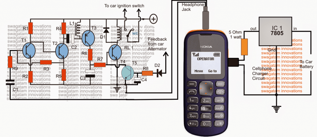
The design is basically a transistorized audio amplifier circuit, which is positioned for amplifying the assigned ringtone from the adjoining cell phone modem. The cellphone shown with the circuit stays permanently attached with the circuit and forms the integral part of the whole system.
The diagram shows a NOKIA 1280 cellphone as the modem, however any cheap cellphone may be employed for the purpose provided the cellphone includes the "assign tone" feature discretely for the particular selected numbers.
The number of the owner or the user is first stored and assigned with a suitable ringtone available within the cellphone modem so that the modem responds only to the owners phone and not to any other irrelevant numbers. The default ringtone of the modem is set to "empty" in order to mute all other unwanted calls.
When the owner calls the modem cellphone, the ringtone is detected by the circuit and amplified to a level sufficient for the relay to get energized. The relay stays energized for so long as the call remains connected.
Configuring the Relay Contacts
Since the relay contacts are configured or integrated with the ignition switch of the car, immediately triggers the ignition system of the vehicle starting the engine and the whole system.
A feed back from the activated alternator makes sure that the relay is instantly shut off irrespective of the call duration from the owner's cellphone.
The car ignition thus is able to start without the owner or the driver having to get inside the car and go through the manual operations. The car starts remotely through the owner's cell phone, a fail proof and a foolproof procedure yet as cheap as anybody can think of.
Parts List
- R1 = 22k
- R2 = 220 Ohms,
- R3 = 100K,
- R4,R6,R7 = 4K7
- R5 = 1K
- R8 = 33K
- R13 = 100 ohms,
- T1, T2, T4, T5 = BC547
- T3 = BC557,
- C1 = 0.22uF
- C2,C3, C4 = 100uF/25v
- D1, D2 = 1N4007
- L1 = 40 mH coil, example: a piezo buzzer coil will do.
- diode = 1N4007
- Relay = 12V/SPDT
- Modem = NOKIA 1280
The charger section is shown in the diagram, and needs to remain connected permanently with the attached cellphone modem.


Questions & Answers
This circuit is very sensitive that drives the relay during mobile charging.
Can you please reduce the sensitivity of the circuit to drive the relay during the ring only??
Did you include L1? Please also connect a 0.1uF capacitor parallel to L1…these two will take care of any spurious activation of the relay.
Dear Swagatam Majumdar
I have included L1 from the beginning.
When I connected a 0.1 uF parallel with L1 the circuit increased sensitivity and relay 1 energised as soon as I turn the power on.
I cant reduce the sensitivity , What can I do ?
Please help me.
thank you
Dear Sasa, I did not face such problems in my circuit so it would be difficult for me to troubleshoot your circuit. For me L1 completely solved the relay triggering problem which was occurring every time the charging was being initiated internally.
for reducing sensitivity you can try connecting the relay across T3 collector/ground and eliminate the entire T4 stage.
Dear Swagatam
I have connected the relay across T3 collector/ground and eliminated the entire T4 stage.
but the relay does not energized
can you please help me
thank you very much
Dear Sasa,
In my circuit I did not have any such problems, so it would be difficult for me to troubleshoot…have you used NOKIA 1280 or NOKIA 1200 for testing it? I tested the design with these phones as modems and it worked flawlessly
.Dear Swagatam,
I have you used NOKIA 1280.
The circuit energizes the relay as soon as I put the power on and deenergizse agin.
It also energizes the relay if I touch the input wire of the capacitor C1.
thank you
Dear Sasa,
There's certainly something not correct in your circuit, I have built so many prototypes so far and all have worked perfectly, touching the input wire should not disturb the circuit operations.
what did you use for L1?
What the L1 do when circuit is activated?
it'll prevent the circuit from false activations due to cell phone's internal RF disturbances.
What can I use for L1? Pls help
L1 can be a standard "buzzer coil", the one which are used for driving piezo electric transducers, or you can make it yourself by winding about 1000 turns of 32SWG wire over any ferrite material.
Where can I get Buzzer coil?
Can I use 'Inductor Choke Coil' in place of L1?
If yes then what value?
any coil around 40mH will do, or do you have a small spare relay, you can use its coil also for L1
How can the car be stopped wiz the phone call?
by calling the modem from the assigned user's cellphone.
But according to the diagram, the relay is supposed to only start the engine & to stop any engine there must be a connection between the ignition system & the vehicle's ground so am very confused about how it can stop in the above diagram, thanks.
the above circuit will not stop the car, as you rightly said it will only start the car….you will have to include a flip flop relay stage additionally which can be wired in series with the spark wire….this relay can be toggled for stopping the car.
kakooza connect the indicated relay wires parallel with the car ignition key switch terminals…make sure to take the help of a qualified auto technician for the installation…
How can Uadd a flip flop relay stage
it's shown here:
https://www.homemade-circuits.com/2012/01/how-to-build-gsm-based-cell-phone.html
Sir,I have connected everything accordingly, im also using nokia 1280 as the modem, before i call to the phone, it already has a voltage of 2.5V at the headphone jack…the problem i have is when i call to the phone, I can hear the ringing tone thru the piezo buzzer at L1, but my relay doesn't get energized…secondly, I have connected my relay to a DC 12V (8 pcs of 1.5V batteries) supply and used a 12V DC motor to replace my car engine…Is that ok????
RaJ, use a 12V 1 amp power supply for testing the circuit instead of battery, do not use any load with the relay initially until the relay operation is confirmed.
connect a LED with 1 K resistor parallel to the relay to confirm the operation, this will verify whether the relay transistor is conducting or not…
Sir, I have also given a 6V supply for circuit as I'm using a 5V relay,,,I can detect a voltage of 4.5V at the T4, but it doesnt seem to reach the diode or the relay..Pls advise me ..
test by connecting an LED across the relay coil
Thank u sir,,one more thing,, the plus sign in your circuit stands for how many volts Sir?? And should I use a 12V relay or 5V relay is good enough??
12V supply is recommended, through a 7812 regulator…use 12V relay for a 12V supply
Sir, last question, headphone jack has 3 wires, are the 2 headphone wires in your design the 2 positives or is it one negative and one positive???
One wire will join with the largest terminal, other wire can be connected to any one of the smaller terminals of the pin
connect the ground wire of the circuit with the largest terminal of the pin
Sir, my only problem is when I switched on the voltage supply for circuit, it automatically starts the system and relay works without me calling the phone,, I'm using Nokia 1280.. Pls advice me sir,, as I need to finish this project in 5 more days Sir…Tq Sir..
Rinosh, the relay will operate only if T4 conducts, and T4 will conduct only if T3 conducts, but T3 will never conduct without a music trigger input.
so check why and how these transistors in your case?
T3 might conduct without music input if C2 is faulty or it is connected wrongly
sir can u make the same circuit to controll(on ,off) a.c appliances
arun, you can use this circuit
https://www.homemade-circuits.com/2012/01/how-to-build-gsm-based-cell-phone.html
Foes this circuit only works with nokia phones or?? Because I.used Samsung phone and it didnt work. The first relay goes on clicking. And the second relay only works when the audio jack is touched. please explaim
hi Mrs swagatam am yet doing my project in my diploma in electrical engineering , and I chose one of your do to make it on my own but something is missing to me. what all I need is the write up of the “cellphone controlled car starter” I need your help.
Hi Zubairu, the circuit is elaborately explained in the above article, you can read it and create your own write up from the given details.
OK thank sire Mrs swag. I will do that, but one more question when the circuit is built, and in terms of operations if I operate the car that is when d car is started, what next will be the second, to off the car ?
it will trigger the ignition system for a second or two, and this needs to be a momentary action, once the engine is started the relay no longer needs to remain ON. The car can be stopped as it is done normally by turning off the gas to the engine….you can consult an automobile mechanic to learn the details and let me know if you need any modifications in the circuit
OK thank u sire Mrs swag. i will keep it up any information or modifications I will let u know.
pls Mrs swag how do I summarised the cellphone controlled car starter circuit diagrammatically in block
there’s one pre-amplifier stage at the input using T1/T2, T3 is the amplifier stage, T4 is relay driver stage and T5 is the feedback stage
thank sir Mrs swag regard your’s
hi mr swagatam, pls i need a reference on cellphone controlled car starter!
Sorry, i did not understand what you mean!
If called and the car has started example of cars like harrier ipsum etc. Then if I want to switch it off ,how do I go about it my master SWAGATAM, can making a second call switch it off with the above circuit.thanks
Hi Davis, This circuit is only for starting a car. Switching OFf can be simply done through the ignition switch.
Just make another circuit like this one for starting with a second phone and make and use a bistable multivibrator for switching off.
Hi Swagatam. Why not make the circuit as a tone detector that can understand or discriminate between tones so that it can be used as a multipurpose ie, on or off just using one phone and one circuit. It’ll be nice to have that circuit.