In this post I have explained how a single LM324 IC can be used to create an adjustable voltage regulator circuit with overload and over current protections.
Basic Working
A basic IC LM324 quad operational amplifier regulates an unregulated 28-volt input source to approximately ±0.02%, resulting in a 1 amp 0 to -20 V supply.
The quiescent current is below 10 mA, and the input voltage can fluctuate between 24 and 28 V. An overload indicator is provided by a light-emitting diode, and its level is determined by the resistance of resistor R8.
Due to the need for two separate voltage sources—one main and one reference—along with the related rectifiers, filter capacitors, and reference regulator circuitry, full-range, efficient power supplies are frequently large and costly.
However, a regulated power supply that delivers constant current 1 amp with an adjustable 0 to 20 volts with foldback current limiting and overload signaling only needs one unregulated source of around 26 volts dc and one ground-sensing LM324 quad operational amplifier.
Circuit Description
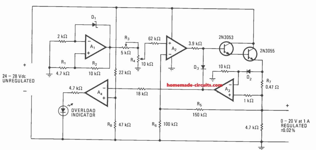
Regardless of load variations, this LM324 voltage regulator circuit is able to maintain line and load regulation within ±0.02%, even while the input voltage fluctuates between 24 and 28 v dc.
The regulator requires a maximum of 10 milliamperes of current while it is in a quiescent state.
The self-biased, constant-current amplifier indicated as Amplifier A1 generates a steady reference voltage.
The breakdown voltage Vz of the zener diode, D1, determines its reference voltage output, V1, which can be calculated using the following formula:
V1 = Vz[1 + (R1/R2)]
For the numbers displayed in the diagram, it is around 9.1 v.
After V1 is reduced to the desired level, we want feedback voltage V2, and this is then amplified by A2.
Subsequently, the Darlington output stage raises the output voltage to:
Vout = V2(R5 + R6)/R6
Variable resistor R3 sets the voltage at precisely 20 volts when R4 is at the highest possible voltage setting. R4 then adjusts the output voltage across its whole range.
The figures displayed indicate an output stage gain of 2.5.
While the load varies, amplifier A3 keeps an eye on the regulator's output current.
It does a comparison between the voltage across diode D2 and the extremely tiny resistance R7.
The output of A3 goes down each time the former is larger than the latter, biasing diode D3 forward and lowering the output voltage by cutting off the drive to the Darlington stage.
If the load keeps going up, the output of A3 drops to the point where amplifier A4 and a light-emitting diode may detect an overload problem.
If required, resistor R8's value can be altered to alter the circuit's overload tolerance.
The number of devices can be decreased from three to two by substituting the output transistors with a single power Darlington, such the 2N6050.
Parts List
- Resistors are 1/4 watt 5% CFR unless specified
- 2k, 22k, 18k, 47k, 100k, 150k, 3.9k, 1k = 1 each
- 4.7k = 3
- 0.47 ohms 2 watt = 1
- 5k preset = 1
- 10k pot = 1
- Semiconductors
- D1 zener diode = 9V 1/2 watt
- D2, D3 1N4148 = 2
- IC LM324 = 1
- Transistor 2N3053, 2N3055 = 1 each
- LED 20mA, 5mm = 1


Questions & Answers
I need an adjustable linear current regulator, the op-amp/MOSFET type and operated with a dropout near 0.1 V or lower. It can be based on LM358, but I’d like it to be fast, so TLV2461 might make sense, or TLV2462 if its channels are independant. (I’m guessing I could buy them online, but I’m confused about how the circuit is put together.) I can get IRLB3034 or IRLZ44N, I think.
It’s a low differential voltage low-power issue, and the rails aren’t perfectly stable, plus I want them to brightly drive 300mA 1W LEDs, 700mA 3W LEDs [maybe as 350mA × 2 regulators], & nominal 5W LEDs (not sure of current, but it’s likely similar to other 5W LEDs you know about), but turning them dark & then promptly on-steady but mainly only for very brief “on” periods. I considered TPS2552 & TPS2553, but both because of my intention of using flying leads and because of the soft on/off, it would be too slow turning them on & off; they need to always be completely dark or on-steady, not ramping, so I need help using the circuit my 1st paragraph mentioned.
Hey, I think the following circuit should be able to solve your problem. Let me know your opinion on this. For calculating R1, R2, please use the following calculator:

https://www.homemade-circuits.com/voltage-divider-calculator-software-potential-divider-calculator/
IRLB3034 is a MOSFET.
IRLB3034 has a resistance that adds to Rs.
Does TLV2462 drain the gate?
What does each TLV2462 pin connect to, for 2 different LEDs, each with an isolated ground and different Vs, perhaps different LED wattages?
Is there a way to determine the Max LED Current for the 5W by nondestructive measurement?
The mosfet resistance does not mess up the current math since the feedback taps right before the sense resistor.
For the tlv2462, it can handle gate draining natively because its push-pull output stage actively sinks and sources up to eighty milliamps to quickly charge and discharge the gate capacitance.
For the dual channels, channel 1 uses pin 3 for ref, pin 2 for sense, and pin 1 for gate, while channel 2 uses pin 5 for ref, pin 6 for sense, and pin 7 for gate, with power on pins 4 and 8, assuming a shared ground.
If you want to check the 5w led max current safely, just hook it to a bench supply in constant current mode starting lowest, then ramp it up slowly while watching the heat and voltage until it hits its limit.
Does R1 need to connect to a higher 80mA+ rail for saturating the MOSFET? (The LED doesn’t likely have a very high voltage.)
The voltage drops from the MOSFET & series Rs seem like they should easily add up, with only the 0.1V-higher voltage on the positive power Vs rail many times.
I don’t know the voltage or exact temperature either. I do plan to keep the LEDs heatsinked & protected from 60°C+ with a cutoff, but loads & resultant heating will vary, and I want to keep the LEDs [properly] operating when conditions allow.
Thanks.
R1 and R2 are just a voltage divider to set the reference so they don’t need a high current rail, but powering the op amp itself from a separate higher rail like 5v or 12v is actually necessary if your main led power rail is only 0.1v higher, because the mosfet needs 4.5v to 10v on its gate to fully turn on and stay under that tiny resistance, otherwise it will choke and fail the dropout target.
The math for the 0.1v drop still works out since the mosfet drops practically nothing at 1A and your sense resistor will only take 50mv to 80mv as long as the gate gets enough voltage from that higher op amp supply. You can check it while it runs by measuring the voltage straight between the mosfet gate and source pins to make sure it hits at least 4.5v.
I don’t know the design forward voltages for the LEDs, but I should be able to find matching rails if current is regulated, since, except for the 5W, for which I know neither, I know the design currents? Would I be better-off sharing the loads between S8050, SS8050, S8550, and/or SS8550 TO-92 BJTs instead of the MOSFETs?
Thanks.
No, switching to s8050 or ss8050 bjts would actually ruin your low dropout goal because standard to-92 bjts have a saturation voltage of half a volt or more at those higher currents, whereas your IRLB3034 mosfet drops practically nothing due to its two milliohm resistance. BJTs also need continuous base drive current and don’t share current well without extra balancing resistors, making them a much worse choice than the mosfet for this. As long as you know the target currents, you don’t necessarily need to know the exact forward voltages beforehand, just that your supply rail needs to be high enough to cover the led forward voltage plus your tiny sense voltage and the mosfet’s negligible drop.
The main led power rail is only around 0.1v higher, & the LEDs are <1A/ea. How do I power the op amp itself from the separate higher rail?
Thanks.
To do this you just connect the op amps positive supply PIN 8 to your separate higher rail like 5 or 12 volts and tie its ground PIN 4 to the main shared ground while leaving the low LED power rail connected strictly to the LED anode since the op amp itself is running on that higher voltage its output can swing way high enough to fully saturate the mosfet gate. Even though the LED rail has almost zero headroom, just make sure your reference resistor divider is tied to that same clean higher rail so the math stays stable and you can verify success by measuring the gate to source voltage to make sure it hits at least 4.5 volts while everything is on…..
What do you mean by “reference resistor divider is tied to that same clean higher rail?” What type of dirtyness is to be avoided in what way?
Which grounds & matching positive rails can be isolated? (Some of the available rails are sensitive/vulnerable to stray voltages from outside of their pairs. Using the dual-channel op-amps economically is good too.)
Will the circuit keep the current constant & unchanged by LED temperatures & resistor temperatures?
Please do not overthink, please give me the correct voltage figures, I will try to provide you with the correct values for the previous op amp based regulator…
Can the R1s be 10MΩ, the RSes be 1/2W 0.1 ÷ Max LED Current or less -set preset trimmers, & R2s 1/10W preset trimmers? What range should they be? Do all need to be adjusted to produce proper current-control over different LED values and VS values? How high can the R1s be, if not 10MΩ? (The heatsink temperatures will be <60°C.)
Which grounds can be separate, per circuit? Can the LED VSes be separate without a 2nd op-amp?
Can you make a diagram for the 2-LED circuit (different LED values for same 2-channel op-amp) with formulas & pins?
Yes, R1 can be 10M, but very high value is not always good because leakage current can affect the operation. The RS resistor should be selected according to the required LED current, and R2 preset can be used for adjustment. But all these values do not need to be adjusted for every LED, only when the LED voltage or supply voltage is changed a lot. I will check the exact practical range and update it. You can use separate grounds only if opamps are independent, single opamps.
How about with LM358 & IRFZ44N, ~15 to 20V VCC?
It will work.
If you use both the opamps then you will need a common ground.
Sir,
Thank you for being online.
Would there be a circuit to be put in between a 120vac 800w battery backup supply and a 120vac 450w air conditioner? Every time the compressor kicks in there is a 2000w, less than 1 sec spike that trips the battery backup.
Hello Neil,
You can either add a soft-start circuit in between, if that is ok with your compressor, or add a bank of super capacitors to handle the momentary surge in the load current.
hola inge..la fuente de 20 voltios y limite de 1 amp, se puede modificar para que la corriente sea variable? hay que modificar algo en A3? graciaw
Hello Ober, you can change the R7 value to change the max current capacity of the output, which cannot exceed 5 amps in the shown diagram, for higher amps you may have to also replace the 2N3055 with some other high power BJT.
To make the current variable, you can connect the two outer terminals of a 1k preset across the R7 resistor, and connect the A3 (+) input terminal with the wiper terminal of the preset via the existing 1k series resistor.
Hi, Sir.This is what i have been looking for to add to my hobby tools. R7 = 0.47ohms. Do i make it smaller in order to get a larger current?
Hi Johnny, yes that’s correct, make it smaller to increase the output current…
Good day, Mr. Swagatam. You truly are a man of your word. I did not expect to get a response so promptly since this is a very old post, but you did answer my question. This is the second time you did this and i appreciate it very much. Thank you for making time for us.
God bless.
Thank you so much Johnny for your kind words, it is much appreciated, and it’s always a great pleasure to help and reply my visitors on this blog. God bless you too!
Good evening Sir.
Thanks for the great work you are doing.
Sir, I need a circuit diagram for a digital voltmeter and ammeter module. That will not use programmable ics. But ics that are easy to find
Hi Ngang, I think you should try the following concept, however I am not sure whether the ICs are still available in the market or are obsolete.
https://www.homemade-circuits.com/how-to-make-digital-voltmeter-ammeter/
Swagatam bhai, I need your help. I have a Yamaha SRX600 for which I am trying to make a regulator/rectifier. its manufacturer suggests the following specification
Voltage Regulator/Rectifier:
Type Short Control,
model SH565 make Shindengen 14-15V
Capacity 12A withstand voltage 200V
Generator is VCD48/Nippon Denso 14.5V 11A at 5000 rpm
It is not available where I live. Perhaps this model is obsolete because this bike is 1986 model. Normal 2 phase and 3 phase RR units available locally do not work, recently I fried one.
It has 2 wires coming out of the stator, none of them is grounded. Both of these wires if connected directly gives current, alone they don’t conduct spark when touched the ground. Only when they are paired together makes it spark.
I tried one of the regulator circuit from your collection but it did work. So I thought I will ask you for your help.
looking forward to hearing from you
Irfan bhai,
Please check the voltage between the two connected wires and the ground. I guess it should be an AC.
If you find the voltage as per the desired level, you can then connect this voltage source to the first regulator circuit which is explained in the following article:
https://www.homemade-circuits.com/3-phase-motorcycle-voltage-regulator/
Let me know how it goes.