
Hi Friends, I am Swagatam. Most readers know me through homemade-circuits.com, a website I started in 2011 to share practical electronics knowledge with hobbyists, students, and working engineers.
Some people also know me by the name Swag, Swagat, Sagar…

I completed my electronics studies at DIPIETE in 1994 and since then I have spent decades working hands-on with electronic circuits, learning how they actually behave beyond textbooks, you only learn that by doing.
About homemade-circuits.com
I started homemade-circuits.com with a simple goal, to make electronics concepts easy to understand and genuinely useful for people who want to learn and build circuits themselves.
Before this site, I worked as an electronic circuit content writer at Brighthub. Then in the year 2013, I started the site homemade-circuits.com.

How This Site Is Different
On homemade-circuits, I personally read and reply to comments. Over the years, I have answered more than 50,000 circuit-related questions, helping readers troubleshoot problems and improve circuit designs, step by step.
Many circuits published here get refined through these discussions, becoming more reliable and practical over time.
A Bit More About Me
Outside electronics, I am an animal lover. I have rescued dogs, cats, and birds, and one long-term goal is to build a shelter for injured and abandoned animals, still working towards that.
Stay Connected
If you need help with any circuit on this website, post your question under the relevant article. I always try my best to provide clear and practical guidance based on experience.
Thank you for visiting homemade-circuits.com. I hope this site helps you learn, build, and troubleshoot electronic circuits with confidence.
Our Esteemed Engineers who helped this site to grow with their Valuable Contributions:
- R. Girish
- Abu Hafss
- Ali
- ERSA
- Robin Peter
- Selim Yavuz
- Ainsworth Lynch
- Vasilis K
- Syed Asim
- Henry Bowman
- SS Kopparthy
- Ajay Dusa
- Ankit Negi
- Navneet Sajwan
- Valerian Meyers (Val)
- Swagatam
- Matrix
Some important names could be missing here, if you think your name deserves to be here please inform us through a comment or through the contact page, we'll update it immediately.
Questions & Answers
I have a heating element out of an old dishwasher that I would like to heat rainwater with and to keep it at a constant 40 to 45 degree to prevent freezing. Is this possible and do you have a circuit I could build on hand. Thank you from a retired newbi.
Can you please post this question under a relevant “temperature controller” article, i will try to solve it for you…
Ok I will try that one for you.
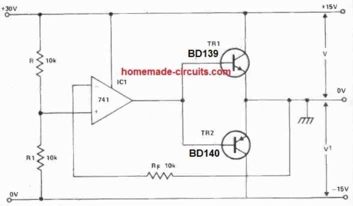
Hi, can you advise on a design for a solar powered dual power supply for op-amps, for example +-12v ?
Hi, you can try this:
Thanks, that was super quick !
I’ll get right to the point: is there a simple way to have LED’s not go ON/OFF but rather with a very short ramp-up and ramp-down, like incandescent light bulbs do? And this in the simplest/smallest way possible. So I assume with capacitors rather than with PWM. I would like to incorporate LED’s as direction indicators in model cars. Any suggestions would be highly appreciated. I already read a lot on the subject here but am looking for more directions and tips. Thank you in advance, Dirk
That looks possible, to provide a slow fading and rising effect to the LED using a transistor driver. So for this we can use an NPN transistor driving the LED at its collector, with its base getting the ON/OFF switching voltage through a resistor, and a capacitor connected between its base and ground executes the soft ON/OFF on the LED.
Let me know if you find this OK…
My god, you are fast! 👏🏼 I think I could use this information but as a novice I would probably struggle with finding the right values for the components. Maybe not for resistors but more for the capacitors and transistors, power supply etc. I’m literally the opposite of you regarding knowledge on electronics 😞
No problems…you can try the following set up for the proposed aapplication:
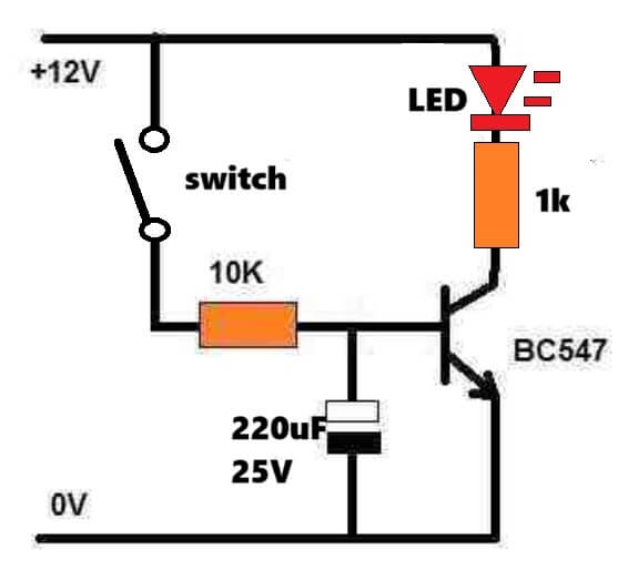
The LED resistor, ad transistor base resistor can be adjusted as per the LED current, same for the transistor, and 220uF can be changed to adjust the fading effect delay…
Thank you very, very much for your time and knowledge.
sir, I need a over load cut off relay which will cut off say above 500watts at 230v ac . However when the over load is removed or the power falls below 500watts it should connect automatically. This is to avoid excess usage of power by several rooms simultaneously which will damage the wiring at the same time and also to avoid manual intervention required like fuse, mcb and other conventional over load circuits.
Ravi, you can try the concept explained in the following article:
https://www.homemade-circuits.com/mains-ac-overload-protection-circuit/
Since you do not want the circuit to latch, you can remove the R6 resistor link from the circuit.
Also, the opto coupler can be any 4 pin standard opto coupler, it does not need to be an LED/LDR type opto.
Therefore the push button can be also removed, and P1 can be replaced with a 10k resistor.
Just make sure to connect a 1k series resistor with the collector of the opto coupler transistor, so that the base of the NPN BC547 transistor remains safe from any over current situation…
Sir i thank you for your quick responce. I think if relay latch is removed it may start chattering. once live line is disconnected led of opto coupler will not glow which may de energize tht relay and connecting the live line again. However I will try to mody the circuit to over come this problem. Thanks for the idea.
You are correct Ravindran, without latching, the relay would chatter at the cut-off ranges, so latching is a must. Or you can consider adding a delay network across base/emitter of the BC557 transistor…
Hello Swagatam 🙂
Please help me find a scematic how to build an Sequential Turn Signal Light for Cars – 12V ordinary lamps!
Like the running light on an old Ford Thunderbird -66 car or like an Mercury Cougar turn light.
Is it possible to build this circuit with Mosfet IRF 511 for lampbulbs. Not LED lamps.
I will be very grateful if you can guide me.
Greetings from Kurt in Sweden
Thanks Andersson,
I can surely help you, please let me know if you want the LEDs to illuminate one at a time while chasing, or illuminate the whole bar one by one and then once the whole bar is lit, shut the whole array and start again??
Hi,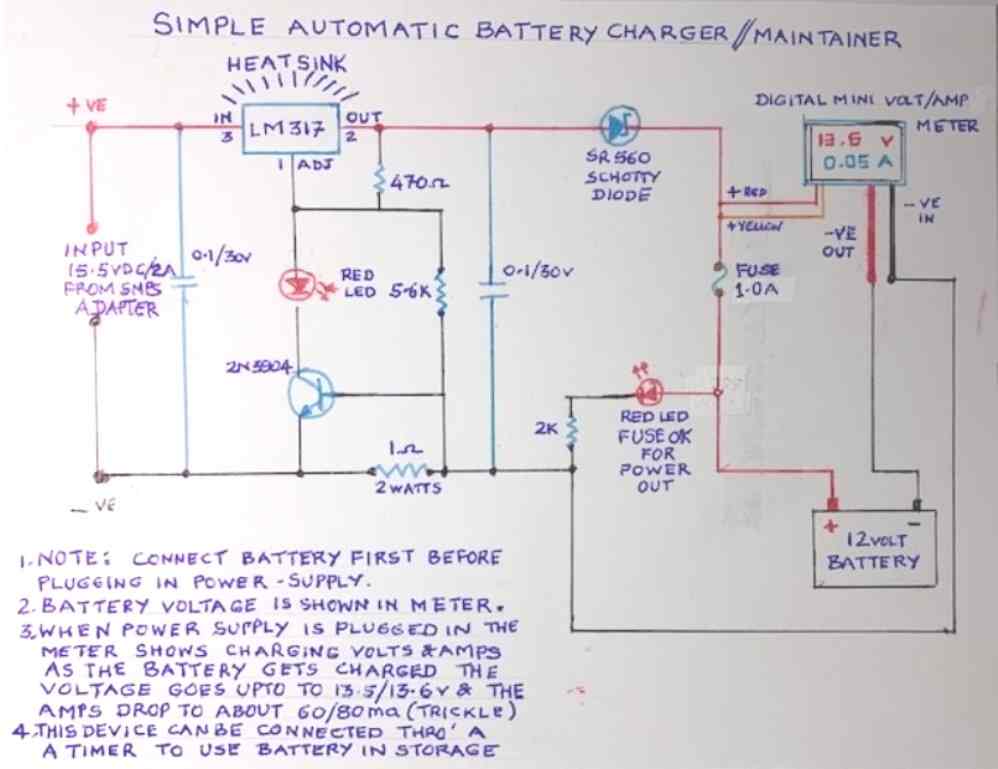 )
)
In my micro-controller based system, I want to add a battery with charging circuit to power the system as on-line UPS. I have studied your different battery charging circuits and want to use LM317 based battery charging circuit designed by Mr. V.
(
I want to detect the presence / absence of battery and the battery charging current.
My question is, How should I detect that battery is not present and if battery is connected what is the charging current ?
Hi, The best approach would be to put an analog ammeter in series with the positive line that goes to the battery positive…nothing else is required…the meter will show you the presence/absence and the exact current being drawn by the battery….
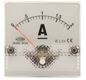
Instead of analog ammeter, I want to use my microcontroller to read the charging current & battery presence. The microcontroller have 10 bit internal ADC.
If I read the voltage across Shunt resistor, the ground supplied to my microcontroller & negative terminal of battery will be at different potential. Am I correct ?
So what will be the best way to achieve this ?
Yes, you are correct…in that case you can employ an opamp based design as explained in the following article, and then integrate its output with your microcontroller…
https://www.homemade-circuits.com/how-to-sense-current-using-op-amp-low-side-and-high-side-circuits-explained/
hi Swagatam
I’m so curious about you.
what’s your nationality?
in other words,where are from?
where were you born?
Hi Saeedreza, I am from India, Mumbai!
IWANT A FM BOOSTER CAN YOU SEND ME TO MY ADDRESS. IWILL PAY THE AMOUNT…PLEASE…..
You can build it by referring to the following circuit:
https://www.homemade-circuits.com/fm-radio-booster-circuit-with-adjustable-gain/
Hello
I would like to make a diagram in TTL electronics. My question is: how to connect OR, AND, NAND gates… to close an output relay controlled by a transistor. I have an input voltage which is at 0V at rest then goes to 5V and remains at 5V for a variable time (several minutes to several hours) then goes back down to 0V when the system is shut down. The relay should not close immediately but after a delay of approximately 5 to 10 seconds. It should only close on the falling edge from 5v to 0v but not on the rising edge from 0 to 5V. This is a pump control for PC watercooling.
Please help me because I know almost nothing about TTL electronics.
J’ai réalisé le montage mais cela ne marche pas. Le relais colle lorsque la tension d’entrée passe de 0V à 5V et décolle, après quelques secondes, lorsque la tension passe de 5V à 0V. J’ai besoin que le relais colle uniquement lorsque la tension d’entrée passe de 5V à 0V et non pas lorsqu’elle passe de 0V à 5V. C’est pour cela que je pensais utiliser une logique en TTL mais je ne sais pas comment l’utiliser.
OK, got it…So your requirement is like this:
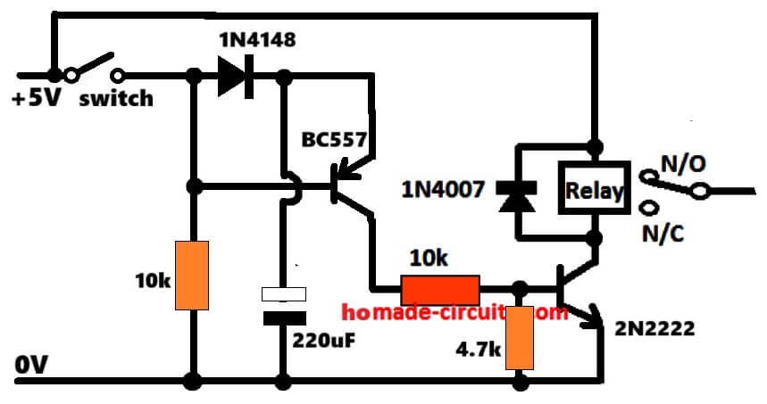
The relay must switch ON momentarily for 5 to 10 seconds then turn OFF, each time the power is turned off.
A TTL or CMOS might not be required for this, a simple BJT circuit should do the trick, as shown below….please make sure everything is wired excatly as shown in the following diagram:
Thank you for your very quick response.
I carried out the assembly and measured the voltages because the circuit does not work. The relay never sticks.
With the switch open, I noted:
– +5 V on the 2N2222 collector –> the relay does not stick which seems normal because the BC557 is not powered.
– 0.00V based on the collector and emitter of the BC557 and the base of the 2N2222
With the switch closed, I noted:
– +5 V on the base and transmitter of the BC557
– +0.4 V on the BC557 collector
– +0.15V based on 2N2222
– +5 V on the 2N2222 collector –> the relay does not stick
I opened the switch and waited 30 seconds to see if the relay closed. The relay does not close. I noted the voltages which are identical to the first case “open switch”, that is to say that the BC557 is not powered.
Here is the correct working of the circuit…..please verify your circuit as per this explanation, and let me know if you have problems understanding it…
When you switch ON the 5V, the BC557 cannot conduct because its base gets +5V, and being PNP it remains switched off, because PNP requires a ground supply….

but here the 220uF charges fully through the 1N4148 diode.
When you turn off the switch, the base of the BC557 now gets a ground supply through the “left” side 10k resistor.
Now BC557 turn ON, and the stored charrge inside the 220uF passes through it emitter to the base of the 2N2222 and the 2N2222 switches ON the relay.
So now the relay swithed ON and remains switcched ON until the 220uF fully discharges cannot supply any voltage to the 2N2222 base.
Rememebr the relay positive is connected directly to +5V and is never switched OFF:
Je vous remercie, j’ai bien compris vos explications.
Je vais vérifier à nouveau le circuit et les composants. Je vous tiens au courant.
Sure, no problem….if still you are unable to build this circuit, just let me know, I will give you the 4017 CMOS version of the circuit, with the same results…
Good morning
I drew a plan of the installation to make this clearer. But I don’t know how to send it to you it doesn’t work with copy/paste and I don’t know where to add an attachment.
I saw your diagram above, how did you do it?
Waiting for a solution to send you the plan.
The system does not work because the relay is permanently stuck and “I need the relay to stick only when the input voltage goes from 5V to 0V (downward edge) after a delay of 10s and not when it goes from 0V to 5V (rising edge)”.
Thank you for your patience
Good morning,
You can send your drawing to my email ID:
contact
@homemade-circuits.com
I simulated the circuit on a simulator, and it works exactly as you want it to be.
You can check the simulation results on the following simulator:
https://www.homemade-circuits.com/circuit-simulator/
Click on “File” and paste the following code inside “Import from Text”
Then you will see the circuit simulation running.
To test the results just toggle the circuit +5V switch, by clicking right on the switch ON/OFF…
$ 1 0.000005 89.03963197220334 85 15 53 5e-11
t 240 208 336 208 0 1 -4.922431788025675 0.0665203196536212 100 default
r 240 208 240 144 0 10000
r 240 208 240 272 0 2200
w 336 224 336 272 0
w 240 272 336 272 0
g 336 272 336 304 0 0
t 160 128 240 128 0 -1 -0.3628835547507189 -0.5052807499620625 100 default
r 160 128 160 272 0 10000
w 240 272 160 272 0
w 160 128 112 128 0
w 112 128 112 64 0
d 112 64 192 64 2 default
w 192 64 240 64 0
w 240 112 240 64 0
c 192 64 192 240 4 0.00009999999999999999 0.5112825541028354 0.001 0
w 192 240 160 272 0
s 112 128 32 128 0 1 false
R 32 128 -32 128 0 0 40 5 0 0 0.5
w 32 128 32 32 0
w 32 32 336 32 0
162 336 112 336 192 2 default-led 1 0 0 0.01
r 336 32 336 112 0 1000
I will send you the installation plan to your email. This is a pump power supply for water-cooling common to 2 PCs which is broken down into:
– to turn on 1 or 2xPc you must first turn on the pumps.
– A detector checks that water is flowing in the circuits and authorizes the powering of PCs which conventionally turn on with their A/M button.
– The PC(s) give 5V on their USB output and will allow the pumps to be stopped when the PCs are turned off. This is what the circuit we are talking about is for.
After redoing the assembly of your 2° circuit, which did not work, and understanding how it worked, I changed all the elements (transistors, resistors, diode,…) of the circuit and started the tests again to realize that the diode was defective. So your 2° circuit works perfectly and meets my expectations.
Thank you very much for your help.
If this circuit can be useful to anyone it can be used.
That sounds great Michel,
Thanks for updating the results.
Glad it is working now…
Is it forbidden to upload your circuits to YouTube?
Yes, it is forbidden, you cannot upload copyrighted work on youtube or anywhere else…
Thanks Swag, I may have asked you a million doubts, but still quick replies are your mode of helping someone. You may have aspired young electronic engineers (exclude me). It would be of great help for someone who wants quick answers for doubts they need to solve. Certain sections like “Home Electrical Circuits”, “Health related Projects”, “Inverter Circuits” and ” Indicator Circuits” etc. are some of the most helpful sections ever. And I am in a great debt to you for desulphating a battery with your magic circuit and the number of questions you answered in it. I hope this community may thrive and become bigger. And as for the lead-acid battery, it is revived. I must thank you extremely for this
Thank you Anto, for your kind words…it is much appreciated, glad my suggestions helped you to solve your circuit problems…
I want to build turn indicator flashing lights for my (pedal) cycle using one or two 3.7v lion cells for power. I have tried this with a 555 and lots of different LEDs but none of my attempts have been bright enough to be seen in traffic in the sunshine. I wondered whether it would be posssible to overload the LED for a very brief bright flash, using perhaps a capacitor, without killing the LED?
Can you suggest a circuit for this? Many thanks for any response. I am in UK.
A 555 flasher circuit can produce awesome amount of light with good quality high bright LEDs, however a standard 555 IC may not work properly with a 3.7V cell. So actually there’s no need of any external capacitors…..
So now you can try a BJT astable flasher instead and check the results:
https://www.homemade-circuits.com/how-to-make-any-light-strobe-light/
Thanks so much for giving your time and expertise. I will try out your strobe-light circuit and let you know what happens.
Happy 2026. I’m from Uruguay, a Latin American country. I cloned your site for my personal use, to learn using HTTRACK. I congratulate you on your work; I found solutions and circuits even for an old laptop that needed a 15-volt, 3-amp charger. I would recommend that you save your entire site as a .rar or .zip file on Archive.org, a US-based site that stores all kinds of data for free and forever, as long as it doesn’t contain passwords or viruses. It’s 100% free and permanent, and it was founded by someone who, through donations, has turned it into a library of Alexandria. There I found a circuit with a single transistor for a battery-free radio beacon for marine use. It’s powered by air currents. It’s a circuit from 1965 and is in Czech. I haven’t translated it yet, but when I do, I’ll upload it to Archive.org in both Spanish and English with the title: Battery-Free Radio Beacon, 1 Transistor. Well, thank you very much from Montevideo, Uruguay. Sincerely, Alex Rademaker. Electronics student. 60 years old, but always young at heart.
Thanks you so much Alex, for your kind words, and interesting suggestions… it is much appreciated.
I will definitely consider your suggestions…all the best to you.
Cheers, and a Happy 2026 to you too!
Hi, my name is Umilghaniyu, I’m student.I want you to help me with a circuit that works like this: a lamp that stays dim when there is no motion, and shines full bright when it detects motion. Please help me with the components I will use as well.
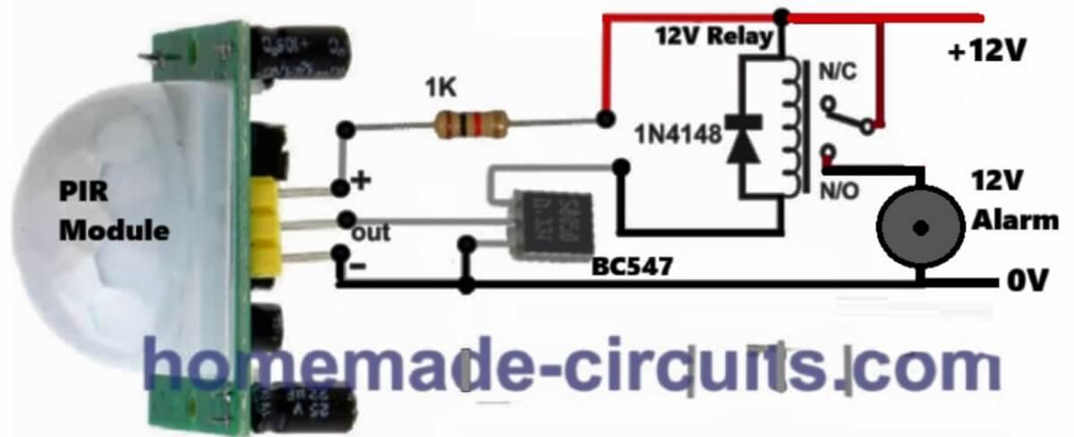
Hi, you can use the following PIR based circuit for your application and configure the relay contacts for making the lamp dim or bright…
Hi Swagatam. Thank you so much for offering up such wise and useful circuitry information. I’m looking for a power inverter circuit that is rated for 300W, 24VDC input, 120VAC/60hz pure sign wave output with short circuit protection and/or a current limiting output so that excess load on the output will not damage components but will shut down or clamp the output. I would also like to have the main power transistors be oversized so a heatsink is not necessary for them. Do you have a circuit already designed that does this. Thank you so much.
Thank you Nathan, that can be quite easily accomplished using a SG3525 IC.
Can you please tell me, whether your transformer is a 3-wire center tap or just two wire unit? I will try to figure out the design…
transformer would be two wire