The circuit explained here is basically a warning signal generator designed largely for automobile application. It triggers a warning signal in a situation when the turn indicator switch is not restored back to its neutral status. The circuit is especially useful for all those cars where the turn indicator system is not supported with an audible clicking sound.
In addition to this, the circuit creates a warning signal as soon as the ignition switch is turned off but car headlights continue to be in the 'on' position. The circuit is specifically designed for 12 volt negative earth cars.
Turn Indicator Warning
When the turn indicator is in the pulsating mode, the circuit sends out a nonstop four step intermittent tones in a random sequence. The functioning can be learned as I have explained below:
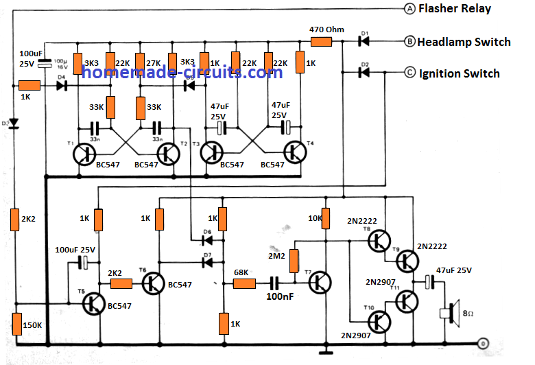
Point C obtains its supply voltage through the ignition switch. Point A is fed with several intermittent pulses from the turn signal relay contact which flashes the side indicator lights.
Each one of the astables produces a frequency determined by the linked T3/T4 RC stage, with a fairly reduced frequency. The second astable T1/T2 oscillates at a varying frequency with respect to the pilot voltage derived via D5 or D4. T5 and T6 produce the timer interval necessary for bypassing the pulsating periods at times when the warning light is not operational.
The alarm frequency is adequately boosted by transistors T7 … T11 for loading the loudspeaker.
Headlight Warning
This car warning circuit could similarly be applied like a 'switch off your headlamps' warning message indicator.
The involved operations may be learned as described below:
Switching the ignition switch "off" takes away supply from point C. Point B, on the other hand, remains energized through the light switch.
This results in both astables and the amplifier stages to continue being functional, apart from T5. This turns OFF the control signal from T6 resulting in its collector to increase to 12 volts and evoking the AND gate D6/D7 to feed the signal frequency over to the transistor amplifier stage.
A two-tone warning signal then begins operating. The terminals A, B and C, should be wired up with the flasher unit, the headlamp switch and the ignition key switch respectively, and you should not modify any of the car electrical substantially except the specified three connections as stated, along with the chassis ground connection.


Questions & Answers
Buenas noches ing Swagatam mis respetos, le doy las gracias de nuevo por solucionar mi caso y estoy muy agradecido por tan rapida solucion ojala todo se pudiera solucionar asi de rapido.
Disculpa usted por casulidad habla español, me gustaria hablar con usted si se puede y si tiene tiempo porque creo que es una persona muy ocupada aunque sea para saludarlo por Skype o facebook, usted me dira.Saludos y mucha suerte.
No problem joseph, I am always happy to help, however communicating verbally will be difficult because I don’t know Spanish, nevertheless you can always contact me through this commenting platform, and I’ll try my best to provide the necessary help!
Buenas noches ing Swagatam de nuevo las gracias por responderme, bueno no te preocupes por no saber español, yo tanpoco se ingles pero bueno estaremo de vez en cuando en comunicacion y cuidate de la pandemia que esta muy fuerte. Saludos.
Gracias Joseph, con nuestros esfuerzos y determinación combinados podremos derrotar a Covid-19 muy pronto, hasta entonces cuídate también.
Good afternoon, Swagatam, I have a small problem, I am 68 years old and I have a problem with hearing. the car overheats because the sensor gives the order to start but the engine is damaged and one does not notice it, well I would like to know if an electronic circuit can be made, indicating if it is working well turn on a led, or if it is locked turn on another led and so one realizes what state it is, I would appreciate it very much if you can help me with this case. Thanks anyway.
Hi Joseph, do you mean to say that you want the existing audible sensor output to be converted to an LED indicator output? Yes that can be easily done.
Good evening, Swagatam, I thank you for taking my case, the problem is that in order for the electric fan to start the sensor that is in the radiator, it gives you the order to work, well the fact is that when that happens, I do not feel it Due to my lack of hearing so far, no problem has happened to me with the electric fan and some component has not damaged me, but I want to prevent in the future, what I really want is something that tells me if it works well, turn on a colored LED And if the motor of the electric fan does not work because it is damaged at that moment, another LED of another color lights up, I really do not know much about it, so I need your help or advice to know what I can. Greetings. do
Thanks Joseph, now I have understood the problem, you want to make sure that the radiator fan is working fine through an LED indication. But that looks slightly tricky because it has to be something related to heat and cooling effect. There has to be something that would remain hot and prevent the LED from lighting up, and as soon as the fan is ON the device will cool down, illuminating the LED.
Let me know if this idea looks workable to you or not!
Good afternoon, Swagatam, I thank you again for taking my case, well if the idea is for me to light up a led on the dashboard to find out how the situation is in the electric fan if it turns or not, if the idea is how you explain it to me and good news can be done, anyway I thank you for your quick responses and there is no rush take your time as necessary. Greetings.
Hi Joseph, I think the second circuit from this article can be applied:
https://www.homemade-circuits.com/lm35-circuit/
However, we will have to attach a small resistive heater with the LM35. for example a 100 ohm 1 watt resistor connected across 12V supply. This will begin heating up the LM35 which will cause the RED LED to illuminate. As soon as the fan is switched ON, the heat will reduce and the RED LED will shut off and green LED will illuminate indicating that the fan is moving and is in a working condition.