• Skip to primary navigation
  • Skip to main content
  • Skip to primary sidebar

Homemade Circuit Projects

Get free circuit help 24/7

  • 1000+ Circuits
  • Privacy Policy
  • About Us
  • Contact
  • Disclaimer
  • Videos – Circuit Test Results
You are here: Home / Security and Alarm / 2 Tone Ringtone Generator Circuit

2 Tone Ringtone Generator Circuit

Last Updated on June 15, 2019 by Swagatam 4 Comments

The IC LS1240A from SGS Thompson is specifically designed for generating a 2 tone ringtone generator circuit. Thus the IC specifically becomes suitable for landline telephones for producing the ringtones when a call is received.

However with little modifications the IC can be easily utilized for normal applications, in circuits where a double tone alarm may be required.

Technical Specifications

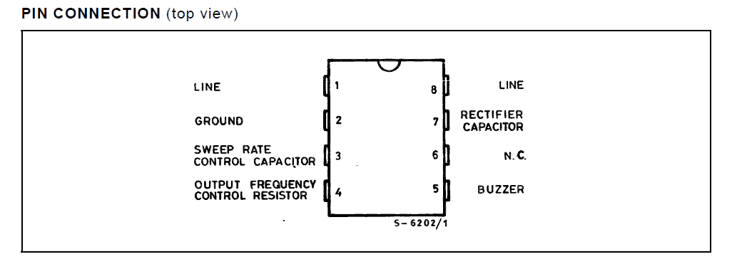
Basically the IC is a 8-pin DIL chip resembling the IC 555 and has the following specs:

  • Very low current consumption yet good audible response at the output.
  • Internal built-in rectifier stage for rectifying an AC input supply, a filter capacitor is also a built-in feature of the IC.
  • Hardly any external components required for setting up the circuit.
  • The tone of the output musical audio can be adjusted externally through a resistor.
  • If the IC os used inside a landline telephone then the supply to the IC is derived from the line voltage via a 1uF capacitor.
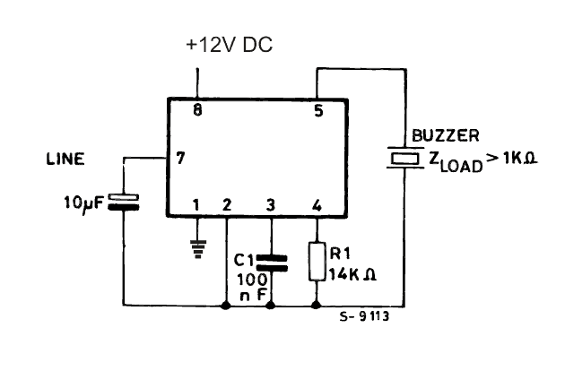
  • The IC is able to drive a piezo electric transducer directly without the need of inductors or amplifiers.
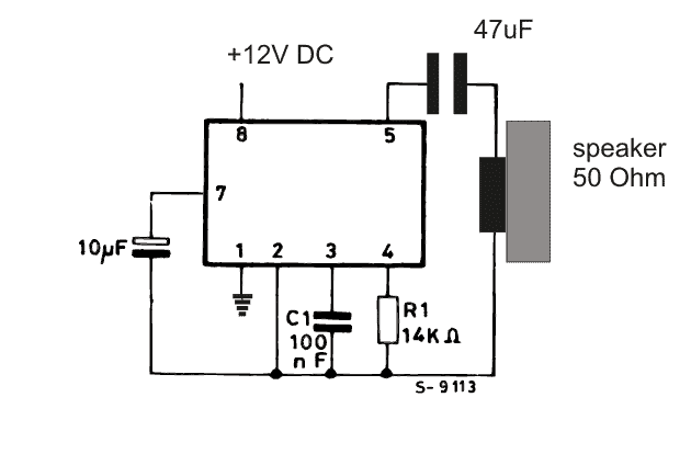
  • The IC is also capable of driving a small loudspeaker directly for generating the musical output.
  • However the speaker must be rated at minimum of 50 Ohms.
  • The following 2 tone ringtone generator circuit shows how to configure the IC LS1240 as a two tone musical signal generator circuit.

Pinout Details of the IC LS1240 dual tone generator IC

Circuit Diagram of two tone music generator using IC LS1240

Two Tone Generator using piezo element

Courtesy:


Previous: Transistor 2N3904 – Pinout and Specifications
Next: Timer based Water Level Controller Circuit

About Swagatam

I am an electronic engineer (dipIETE ), hobbyist, inventor, schematic/PCB designer, manufacturer. I am also the founder of the website: https://www.homemade-circuits.com/, where I love sharing my innovative circuit ideas and tutorials.
If you have any circuit related query, you may interact through comments, I'll be most happy to help!

You'll also like:

  • 1.  Touch Operated Code Lock Switch Circuit
  • 2.  Laser Beam Light Activated Remote Control Circuit
  • 3.  How to Make a GHz Microwave Radar Security Alarm Circuit
  • 4.  5 Simple Alarm Circuits for Protecting your Home/Office from Theft
  • 5.  Patient Drip Empty Warning Indicator Circuit
  • 6.  A Homemade Fence Charger, Energizer Circuit

Please Subscribe (Only if you are Genuinely Interested in our Newsletters)


Reader Interactions

Comments

    Your Comments are too Valuable! But please see that they are related to the above article, and are not off-topic! Cancel reply

    Your email address will not be published. Required fields are marked *

  1. Search Related Posts for Commenting

  2. Kit Jamieson says

    Dear Swagatam,
    I am trying to find a circuit with which to build an accurate stable two frequency AC signal generator.
    The two frequencies I require are 528Hz and 1/13th harmonic of 40.6Hz which I then need to push through an amplifier circuit to achieve a minimum of 200 ohms.
    The voltage input would ideally be 15volt DC, which I wish to switch via an existing frequency generator with a Photomos gate.
    This would hopefully give me a 50:50 528Hz/40.6Hz AC signal output to an amp. switched via the Photomos gate also opening and closing at 528Hz.
    The original circuit is accurate to 3 decimal places.
    Can you help, please?
    Thank you so much,

    Reply
    • Swagatam says

      Dear Kit, I am sorry, I have no idea how this can be implemented?

      Reply
  3. Anil Kumar.K says

    Dear Swagatham
    I assembled this circuit. There is no sound, from speaker/ ceramic transducer.
    My experiments :-
    1) I tried two LS1240A ICs removed from two landphones.
    2) I tried speaker ( 2x30ohms speakers in series.
    3) I used same piezo ceramic transducer (without inbuilt oscillator) from the landphone.
    4) I tested with 9vdc to 17vdc.
    5) I shorted pin 1 (LINE) to pin 2 (Negative).
    Why there is no output….? Does this circuit need AC voltage at pin1 and pin 8….? If yes what should be the minimum and maximum AC voltage range….?

    Regards

    Reply
    • Swag says

      Dear Annil,

      the IC has an internal rectifier circuit so it does not matter whether the input is an AC or DC, it should work with both.
      However the IC has only one negative pin at pin#1, no other point in the circuit is connected with the negative supply, so I hope you have connected this correctly.

      I think your IC may be faulty, you can further confirm the circuit by using a headphone instead of the speaker.

      Reply


  4. COMMENT BOX IS MOVED AT THE TOP


Primary Sidebar

Electronic Projects Categories

  • 3-Phase Power (15)
  • 324 IC Circuits (19)
  • 4017 IC Circuits (51)
  • 4060 IC Circuits (25)
  • 555 IC Circuits (92)
  • 741 IC Circuits (18)
  • Amplifiers (49)
  • Arduino Engineering Projects (82)
  • Audio Projects (83)
  • Battery Chargers (75)
  • Car and Motorcycle (87)
  • Datasheets (44)
  • Decorative Lighting (Diwali, Christmas) (31)
  • DIY LED Projects (81)
  • Electronic Components (96)
  • Electronic Devices and Circuit Theory (34)
  • Electronics Tutorial (99)
  • Fish Aquarium (5)
  • Free Energy (34)
  • Games (2)
  • GSM Projects (9)
  • Health Related (17)
  • Heater Controllers (23)
  • Home Electrical Circuits (98)
  • Incubator Related (6)
  • Industrial Electronics (25)
  • Infrared (IR) (39)
  • Inverter Circuits (94)
  • Laser Projects (10)
  • LM317/LM338 (21)
  • LM3915 IC (24)
  • Meters and Testers (52)
  • Mini Projects (152)
  • Motor Controller (64)
  • MPPT (7)
  • Oscillator Circuits (12)
  • PIR (Passive Infrared) (8)
  • Power Electronics (32)
  • Power Supply Circuits (64)
  • Radio Circuits (9)
  • Remote Control (46)
  • Security and Alarm (55)
  • Sensors and Detectors (115)
  • SG3525 IC (4)
  • Simple Circuits (72)
  • SMPS (30)
  • Solar Controllers (60)
  • Timer and Delay Relay (51)
  • TL494 IC (5)
  • Transformerless Power Supply (8)
  • Transmitter Circuits (36)
  • Ultrasonic Projects (12)
  • Water Level Controller (45)

Follow Homemade Circuits

Facebook
Twitter
YouTube
Instagram
My Facebook-Page
Quora

Feeds

Post RSS
Comment RSS

Circuit Calculators

  • AWG to Millimeter Converter
  • Battery Back up Time Calculator
  • Capacitance Reactance Calculator
  • IC 555 Astable Calculator
  • IC 555 Monostable Calculator
  • Inductance Calculator
  • LC Resonance Calculator
  • LM317, LM338, LM396 Calculator
  • Ohm’s Law Calculator
  • Phase Angle Phase Shift Calculator
  • Power Factor (PF) Calculator
  • Reactance Calculator
  • Small Signal Transistor(BJT) and Diode Quick Datasheet
  • Transistor Astable Calculator
  • Transistor base Resistor Calculator
  • Voltage Divider Calculator
  • Wire Current Calculator
  • Zener Diode Calculator

© 2021 · Swagatam Innovations

We use cookies to ensure that we give you the best experience on our website. If you continue to use this site we will assume that you are happy with it.Ok