In this post I have explained how to connect common 78XX voltage regulator ICs such as 7805, 7812, 7824 etc for getting fixed regulated output voltages at 5 V, 12 V, or 24 V outputs respectively. The input voltage must be at least 3 V higher than the desired output voltage. For example, if a 7805 IC is used for getting a regulated 5 V DC, then its input DC supply must be at least 5 + 3 = 8 V DC or higher. The maximum input DC must not exceed 35 V, otherwise the regulator IC can get damaged.
Importance of 78XX voltage regulator in circuits
A varying voltage can cause drastic consequences to a sensitive electronic circuit, for example a TTL, LS and HC series of ICs cannot tolerate more than 5 volts and can get immediately damaged.
A CMOS IC cannot stand more than 16 to 18 volts.
A relay if operated at voltages more than its rating can become hot and waste electricity unnecessarily.
There are several other issues which might be faced with electronic circuits if the applied is an unregulated one.
For solving the above issue, many high grade yet very simple to configure chips have been designed and are available cheaply and plentifully in our electronic markets.
The 78XX voltage regulator series for example, comes with most of the standard voltage ratings which can be used in conjunction with an ordinary power supply DC for obtaining high grade, clean voltage controlled outputs.
Technical specifications of the 78XX series IC
- Output voltage tolerances are around ±2% at Tj = 25˚C and ±4%
- Line regulation is around 0.01% of VOUT/V of ∆VIN at 1A load
- Internal circuitry is thermal and overload protected
- Internal short-circuit current limit protections are also included
- Output transistor safe area protection is also one of the features of these ICs
Identifying 7805/7812/7824 ICs Pinouts
A classic example can be seen in this article where a 7805 IC is used as a cell phone charger regulator.
Referring to the above circuit diagram
- These ICs have just three leads, making it very easy to understand and connect. The leads are assigned as input, ground and output respectively.
- Keeping the printed side toward you, the left side lead is the input, the center one is the ground and the right side lead is the output.
- The DC from any standard power supply is applied across the input and the ground leads of the IC, the positive goes to the input while the negative is connected to the ground.
- The output is acquired across the output and the ground pins of the IC, the positive being received from the "output" pin and the negative from the common ground line.
IC 7805, 7812, 7824 Pinout Specifications
Most of the common voltage regulator ICs beginning with the 78 prefix, such 7805, 7812, 7824 typically have identical pinout assignments as shown below:
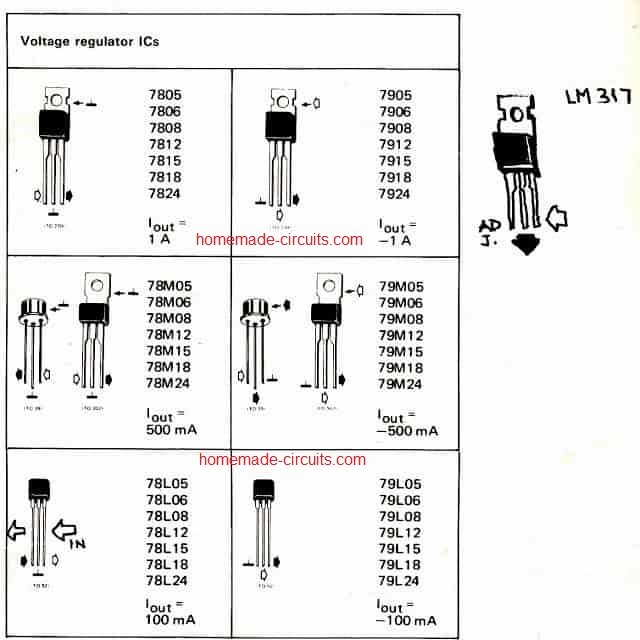
However, in the above chart, we can also see that except the 78LXX, the other variants have slightly different pinout specifications, and needs to be connected exactly as per the given details otherwise the IC may fail to work and produce unexpected outcomes.
The ICs beginning with 78XX are positive voltage regulators, meaning these will accept a positive input voltage across across their input/Gnd terminals and regulate the same across their output/Gnd terminals with the specified fixed voltage output.
Conversely, the 79XX ICs will accept a negative voltage and produce a negative fixed voltage across their relevant output terminals.
The package of the ICs also signify a vital information. The ICs with TO220 package are rated to handle and produce a maximum of 1 Amp current whereas the smaller 78LXX version are rated to handle only upto 100mA.
We all very well know regarding the building procedures a DC power supply circuit using a transformer, a bridge rectifier and a filter capacitor.
It just requires connecting four diodes in a bridge configuration and connect it to the secondary of the transformer, the capacitor goes to the output of the bridge terminals.
The output produced across the capacitor is approximately equal to the rated voltage of the transformer, rather a few volts higher than the transformer spec.
However the voltage obtained from the above simple configuration is never regulated and stabilized, meaning the output from it will never be constant and will vary with the varying input mains voltage levels, which we know is never constant.
How to Connect 7805, 7812, 7824 in an Electronic Circuit
In order to regulate an existing supply to a fixed level, we normally use these 78XX ICs, and these can be very easily connected with any supply source in the following shown manner:
Application Circuit
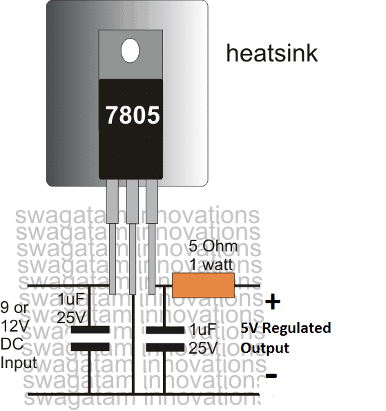
ICs 7812 and 7824 can be also connected exactly in the above shown manner, the only difference being the input/output voltage specifications which will vary as per the IC's ratings.
For example a 7812 will require an input above 13V and will produce a fixed 12V at its output.
Similarly a 7824 will require a input of not less than 26V, and will offer an output voltage fixed at 24V, and so on.
What does the Capacitors do?
We can some capacitors attached across the input and output terminals of the ICs, these are just included to rectify any residual DC spikes and ripples that may exist in the supply line.
According to the datasheet of the IC, the input capacitor is required only if the input source is at a significant distance away from the IC, may be at over a meter away. The output capacitor may be included if you want an improved transient regulation, meaning protection from noise spikes.
The value of these capacitors is not critical any value between 1 uF and 100 uF can be used for rectifying higher frequency ripples, whereas smaller capacitors in the range of 0.1 uF to 0.47 uF can also be attached in parallel to control any possible high frequency entry along the supply rails.
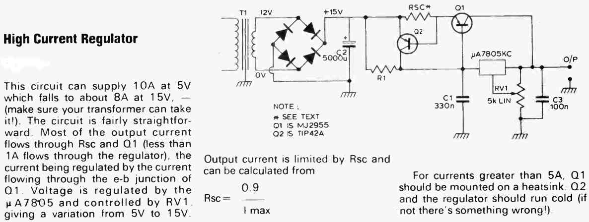
How to Get High Current from 7805 IC (up to 10 Amps)
A 7805 IC is designed to deliver 5 V at 1 Amp maximum current. So if you want to get more than 1 amp from this IC it may be impossible to achieve this, directly from the IC.
However, the following transistorized circuit not only upgrades the IC 7805 specifications to generates higher current up to 10 Amp current but also allows the user to get a voltage as high as 15 V from the 7805 IC.
The following diagram suggests the entire procedure for achieving high current over 10 amps from the IC 7805 and a variable output voltage from 5 V to 15 V.
High Current from 7805 and 7812 IC with Short Circuit Protection
Here's another circuit which can convert an ordinary 7805, or 7812 IC into a high current delivering circuit. The design presented also has a current control feature which ensures that the output transistor is always safeguarded from short circuit or high current over loads.
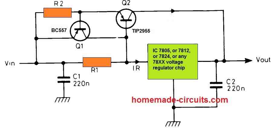
The circuit functions in the following way:
When the voltage drop across R1 exceeds 0.6 V, Q2 begins conducting and it bypasses the voltage regulator IC to provide the full high current from input supply to the output terminals.
Q2 works like a current limiter stage. If the current through Q1 tries to exceed over the maximum tolerable range, the voltage drop across R2 also exceeds 0.6 V turning ON Q2.
Q2 collector shorts circuits the Q1 base with the positive supply inhibiting its conduction and thus switching it OFF. In this way the current is controlled strictly to the desired maximum range.
R1 and R2 can be calculated using the following formulas:
R1 = 0.6 / 0.5 = 1.2 ohms 1/2 watt
R2 = 0.6 / maximum current limit



Questions & Answers
DEAR I WAS USE ENCODER INSIDE REGULATOR IC DAMAGE IC 78M05GRV739 OR 78M05GRY739 WICH IC CAN REPLACE PLEASE SUGEST
Hi, I looked for the details of that IC online but could not find any results.
Could you please tell me the specifications of those ICs, i will try to figure it out for you…
Hi Swagatam;
My circuit parts flow diagram; 1- transformer output DC voltage 21 V with 2200 mF C. 2-a) 7812 b)7805 and 7812 feeds 2 fans with 0.15 A. However fans do not work together at the same time but alternating period. There is slightly heating on 7812 and there is no capacitor at the 7812 output since there is an 2200 mF on the transformer output. Please advise if a capacitor is necessary at the 7812 output or not? Best Regards
Hi Suat,
If the 7812 is not situated too far away from the transformer and the 2200uF capacitor then there’s no need of any extra capacitor at the output of the IC. However there’s no harm in connecting one since adding capacitors at the output of an regulator IC is never a bad thing. A 100uF would be great if you have one otherwise you can ignore it.
Hi Swagatam;
I have a circuit and in the circuit there are pic16f684 and pic16f877a whose source voltages are same as DC 5 V. One will feed 2 BT136s and other will feed 2 relays. My questions are;
1- I should use 2 regulators as 7805 or only one is enough.
2- Please advise if possible to use 2 triacs as a switch at the same in one pic circuit. (because I am able to read AC 220 volt at the BT136 output but that output not able to run AC 220 V and 0.15A fan)
Best Regards
Hi Suat,
You can use a single 7805 for powering both the PIC circuits. I am assuming that the current consumption of the two ICs along with the relays is not over 300 mA.
Two parallel triacs shouldn’t be required, one should be quite enough. If your triac is not powering the load, this could be due to either very low gate current below 5 mA or the triac itself is faulty or maybe the triac pins are not configured correctly.
Hi Swagatam;
I have been using 7805 for the pic16f877a and one of the pins of 16f877a will trigger the base of a npn transistor to switch the 5 volt relay. So voltage to base will be 5 Volts too. Please advise that the ideal value of the resistor should be at the base. Regards
Hi Suat, the value of the resistor is not critical for a normal relay whose coil resistance is between 200 ohms to 400 ohms. You can simply use a 10K resistor at the base of the driver transistor. However, if you are interested to have the ideal value or the precise value, then you can refer to the following article for the formula:
Transistor Relay Driver Circuit with Formula and Calculations
Thanks a lot Swagatam;
I checked the article and I got the matter however to my experiments 10K is good as base resistor at most circuits however in the 5 V PIC programming the resistors applied over 2K to the base I had always problems I really do not know why but as to your article I think about 1k5 will be better and best to test it I think- Best Regards
No problem Suat, glad the problem is solved….the resistor value is also directly dependent on the Hfe value of the transistor
How many volts capacitors should I use if I will have it paralleled to a 7824 with 26-28vdc input?
Thanks.
Single common capacitors across the input and the output pinouts will be sufficient.
O.K. Great! Thanks for a such a speedy response.
Anil
Dear Swagatam,
I am a Mechanical Engineer and not quite familiar with electronics circuit. However I am a certified Trainer in Solar PV systems and I conduct training courses in Design and Installation of such systems. In order to demonstrate to the students (who are from varied disciplines ranging from ITI to Engineering graduates and at times commerce and Arts graduates as well) to connect an appliance such as 5 Watts DC bulb directly to a solar panel just to see if it lights up. It did but the next moment the bulb fused. So I need a regulator which can work with 18 to 21 V DC x about 4 Amps current rating. I was thinking to use IC 7812 but I am not aware of full external circuit. Can you help me in providing a suitable circuit ? Thanks – Anil Garde
Dear Anil,
you can use the second circuit from this article:
https://www.homemade-circuits.com/how-to-make-current-controlled-12-volt/
replace the LM317 with LM338, connect the solar panel directly across C1, ignore the transformer and the bridge rectifier, they are not required.
Make sure to connect the panel with correct polarity…
…7812 will not give 4 amp current, so it can’t be used
The circuit above is not correct as a 5V regulator cos the load voltage will vary depend on the IR drop across the 5ohm resistor. You need to leave the 5ohm out if you need a stiff 5V output.
The shown application is meant for charging a cellphone, that’s why the 5 ohm resistor is included, the actual design can be be witnessed below:
https://www.homemade-circuits.com/how-to-make-simple-dc-to-dc-cell-phone/
for any other application the 5 ohm must be removed.
Hello sir
Can we use 7812 to take negative 12voltage from -24 volt
Hi Prahalad, sorry I am not very sure how to achieve it using a 7812 IC…
Hello sir
I want to convert 130v1amp DC in to 12v8amp DC please help me
Hello Umair,
you will need a buck converter circuit for this…you can refer to this article
https://www.homemade-circuits.com/2016/07/designing-solar-inverter-tutorial.html
Hello Mr. Swagatam I always read up right post. Please can u send me 10 to 20. 1watt led in series on 220v ac circuit.
Thanks in advance
amarjithappy@yahoo.com
Hello Amarjit, you can try the following universal concept
https://www.homemade-circuits.com/2016/07/scr-shunt-for-protecting-capacitive-led.html
you can connect the LeDs in series at the output of the circuit, and use a zener diode having value equal to the total forward drop of the series LEDs.
Dear Swagtham,
I want to use 0.5 watt 4.5 dc volt LED on 220/240 olt AC , please , give me circuit idea.
Thanks
Dear Raman, you can try the following circuit
https://www.homemade-circuits.com/2011/12/cheap-yet-useful-transformerless-power.html
replace Z1 with 5V 1 watt zener diode and replace the 50 ohm resistor with 10 ohm 1 watt resistor
I want the circuit diagram of internal circuit of ic7805 and ic7812
check datasheet
Hello, i have a 7812 voltage regulator. Can i used it on 9v batterry? What is more suitable 7812 or 7805?!
what is your requirement? 9V with 7812 will give you 9V output and with 7805 it will give you 5V
Hi sir. I have a 19v dc 6a source and want to convert it into a 12v battery charger. How can i do that using lm7812 ? I have a couple of 1N4001 diodes and couple of zener diodes, caps resistors. Any advice for a circuitry?
Hi Jason,
you can do it exactly in the manner shown in the first diagram of the following article:
https://www.homemade-circuits.com/2013/04/12v-5-amp-fixed-voltage-regulator-ic.html
Hello sir, need a circuit diagram that convert from D.C (12V 1A) to D.C(5V 20mA ) by using a voltage reglutor 7805.
hello james, you can refer to this article:
https://www.homemade-circuits.com/2012/03/how-to-make-simple-dc-to-dc-cell-phone.html
Hello sir U have any sample circuits of fixed voltage regulator using 7805?
Hello Shamriz, why do you need it to be 20mA.?..it can be be 1amp, that may not be an issue for your load.
Hello sir, need a circuit diagram that convert from A.C(240-110) to D.C(5,9,12,24) volt without using transformer..,.thanks
hello smart, you can try this:
https://www.homemade-circuits.com/2014/02/220v-smps-cell-phone-charger-circuit.html
hi nice to read your article,everything is ok but only i couldn't any article about how to check the component with multimeter(analog/digital) especially the 78/79xx voltage regulator.And highly appreciation to you thanks you
hi thanks very much….these ICs cannot be checked with a multimeter….in fact no IC in this world can be checked using a multimeter, that's just not feasible.