In the following post I have explained a pure sine wave inverter circuit using the IC 556 which forms the main sine wave processor device in the circuit.
How it Works
The presented design actually produces a modified sine wave output, but the waveform is highly processed and constitutes an exact equivalent of a sinusoidal waveform.
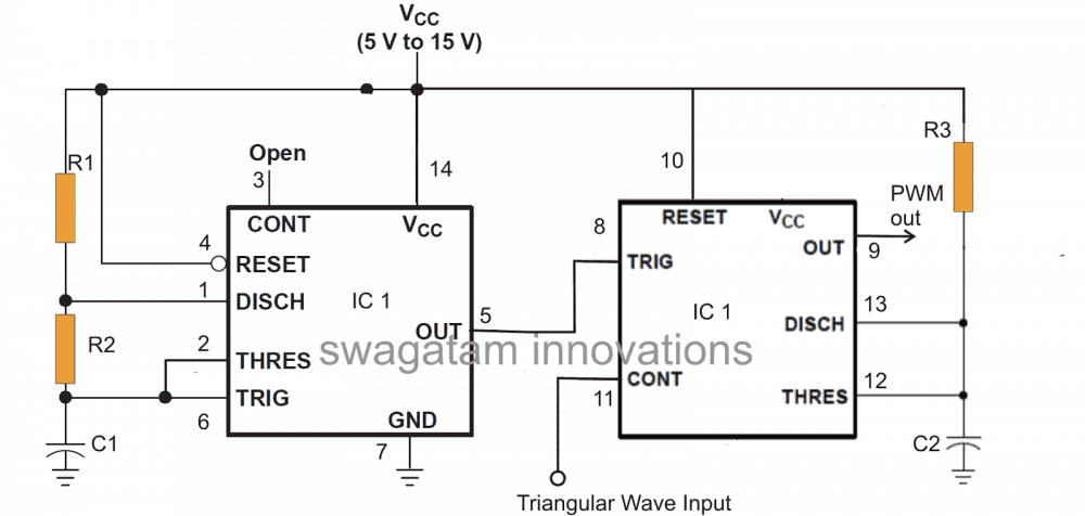
A single IC 556 forms the heart of the circuit and is responsible for manufacturing the required PWM controlled modified sine output waveform.
One half of the IC on the left is configured as a 200Hz frequency generator, this frequency is used for providing the required square wave clocks to the preceding monostable which is formed by wiring up the other half of the 556 IC.
The clocks are received from pin#5 and applied to pin#8 of the IC. The right hand side section of the IC does the actual processing of the above square wave by comparing it to the triangular waves applied at its pin#11.
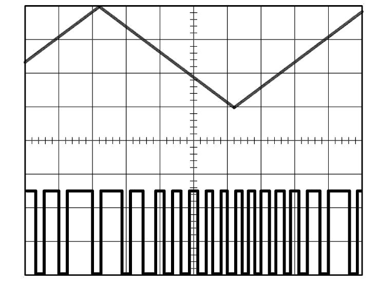
The result is an output at pin#9 which is a PWM, varying in accordance with the amplitude of the triangular waveform.
Ideally the triangular waves can be replaced with a sine waveform, however since triangular waves are easier to generate, and also appropriately replaces the sine counterpart, its been employed here.
R1, R2, C1 should be appropriately selected so that pin#5 produces a 50% duty cycle, 200 Hz frequency.
The 200 Hz is not critical here, however it becomes critical for the IC 4017 stage and that's why it's been selected to that value.
The modified sine wave PWM generated by the IC556 is next applied to the switching stage comprising the IC 4017 and the relevant output mosfet devices. Let's see how it's done.
Parts List
IC1 = 556
R1,R2,C1 = select to generate 50% duty cycle
R3 = 1K
C2 = 10pF.
The output stage
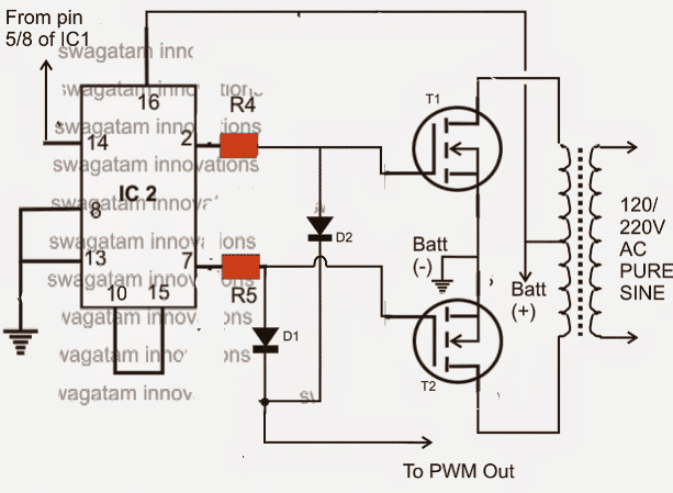
The diagram given below shows the output stage configuration where the IC 4017 takes the center stage. Basically its function is to switch the driver transistors alternately so that the connected mosfets also conduct in tandem for inducing the required mains AC output into the transformer.
The IC receives the clock pulses from the above explained 556 circuit (pin#5/8) and its outputs sequence across the connected transistors alternately as discussed above.
Until here the circuit behaves like an ordinary square wave inverter, however the introduction of D1/D2 with the pin#9 of the 556 transforms the circuit into a full fledged pure sine wave inverter.
As can be seen, the common cathodes of D1/D2 are integrated with the processed PWM pulses from the above 556 stage, this forces D/D2 to conduct only during the negative pulses from the generated PWM blocks.
It simply means that when D1/D2 are forward biased, T1 and T2 are inhibited from conducting since their gates become grounded through D1/D2 into pin#9 of the IC 556, which make the mosfets respond exactly to the PWM pattern.
The above process generates an output across the transformer secondary that's perfectly chopped and processed and equivalent to a sine waveform.
Parts List
IC2 = 4017
all resistors are 1K
D1,D2 = 1N4148
T1,T2 = IRF540n
Transformer should be also appropriately rated as per the requirement.
The Triangular Wave Generator Circuit
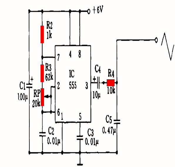
The entire modified sine PWM waveform construction and implementation is dependent on the fed triangular waves at pin#11 of the IC556, therefore a triangle wave generator circuit becomes crucial and imperative.
However there are many types circuits that will provide you with the required waveform inputs, the following is one of them which incorporates yet another IC555 and is pretty simple to configure.
The output from the below given circuit must be fed to pin#11 of the IC556 for enabling the proposed sine wave inverter functioning.
DESIGNED BY "SWAGATAM"
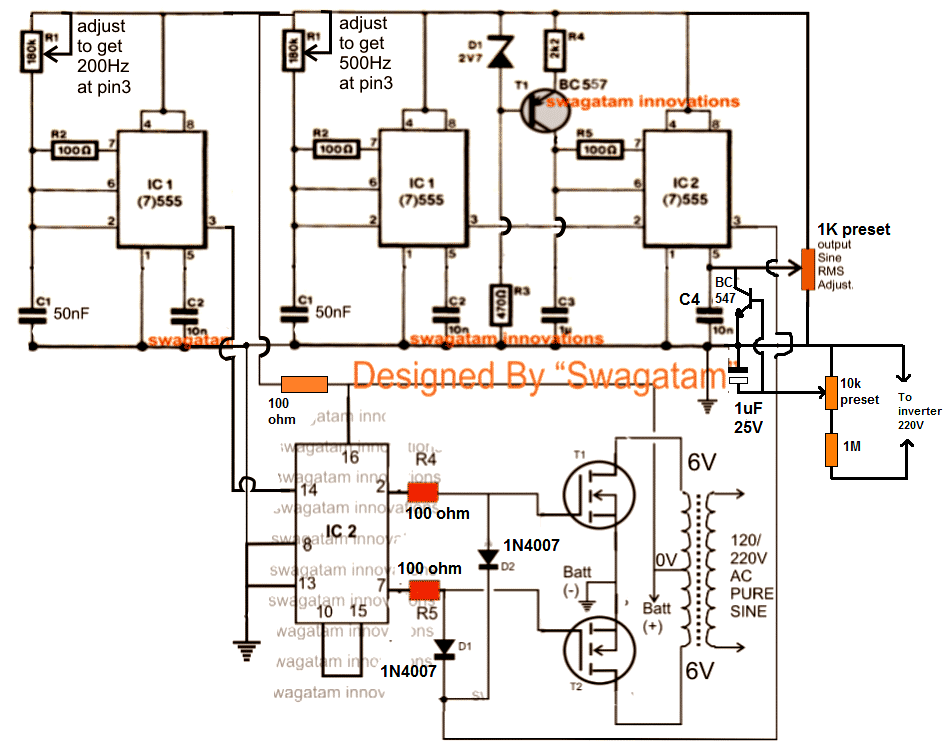
A simpler alternative to the above design is shown below, the configuration would produce same results as explained above:


Questions & Answers
sir
thanks.
good day.
can i know that few your circuit pcb required, how can i get if so price please.
even if gerber file available I will make from my local
please suggest me.
regards.
Gopal raju
9535168189
Thank you Gopal, for your interest in PCBs, however, unfortunately i no longer manufacture PCBs, so I may not be able to provide any help regarding PCB designs.
Good day Mr Swag. Pls my question may not be related to this topic but will like you to direct me to the appropriate tread.
Please sir I need a circuit that will charge multiple 3.7v lion battery with auto cut off from a 5v source. Mean while from the circuit I want to connect a 3v DC bulb to it, so I will like you to include 3v cut off for the circuit from the battery if the bulbs have discharge the battery to a minimum of 3v, since the battery can be charged upto 4.2v.
Thank you for quick response in advance.
Hi Godspower,
you can try the last concept from the following article. You can replace the MOSFET with a TIP127 transistor, and replace the 2N6284 transistor with a TIP122. ZY can be a 3 V zener and ZX can be a 4.2V zener diode, and battery will be 3.7 V Li Ion. Make sure the input current is not higher than 50% of the battrey Ah rating:
https://www.homemade-circuits.com/battery-deep-discharge-protection-circuit/
Good afternoon sir hmm sir I build this circuit and alsudden the transformer start smoking and the 555ic1 get burn and it keeps blowing my 555timer I use 47nf instead of 50nf pls sir help me please
It started when I use 12v/7h battery
Hello David, you must build the circuit stage-wise and confirm the working of all stages step by step, and only then integrate them together for the final results.
If you connect then all together then you might run into problems.
You might also require an oscilloscope to check the PWM waveform.
So what would be the importance of the 10k preset
Both are used for setting up the output voltage
Pls sir what is the importance of the bc547, 1uf/25v capacitor and the 10k preset connected with the 1resistor and why was a 6v-0-6v transformer choosen
I made an inverter circuit with the NE556 IC, 6Hz~286Hz~, works from 12Vcc.
I also made the output transformer for a PEMF device.
It is a 40VA plate transformer
Nimel, the BC547 is used to auto control the RMS voltage output of the inverter….6-0-6V transformer is dependent on the PWM level…you can use other transformers like 9-0-9V also and adjust the PWM accordingly through the right side 1k preset.
In complete many components value not mentioned
Good day Engr. Please, I need circuit diagram of non-center tap inverter..
Sunshine, please search for “full bridge inverter” in the search box
Hello Mr. Swagatam Sir… I am a complete novice at this SPWM scenario. I have been reading and studying your circuits for a very long time… now..
So I discovered this website.. wherein you show and describe some very interesting circuits. So I tried to build up your rendition of the 3 … (7)555 timers and the 4017 combination.
So I started with the first timer – which is to be set at.. 200 Hz. Firstly after making up a breadboard build up… I never could get a 50% duty cycle waveform out. Instead I got… a spike pulse… negative going.. In your description I read that it must be a 50% duty cycle. So… I then decided to read the net… and found a datasheet… in which it described a 50% duty cycle waveform to be created… BUT your R2… 100 ohm.. is actually connected in the incorrect place. It should be connected directly from the +ve line… down to.. pin7 of the 555. This then gives a perfect 50% duty cycle…
SO I carried on… I then built up the second timer… obtained the waveforms.. but could not get a stable waveform of 200 Hz, and 500 Hz… So Mr. Swagatam Sir… I employed my FLOWCODE 8 program… and a simple PIC12F675.. 8 pin chip.. and wrote and timed a loop in which I succeeded in getting a dead accurate – 200 Hz and 500 Hz square waveform..
I then used.. a mosfet transistor with 2… 10K resistors per fet..(2N 7000).. to make up a level convertor… so that the PIC output could be level shifted to 12 volts of the +ve line. All this works perfectly… now… I would like to send you what I have done.. You may also download the FLOWCODE 8 program from the UK servers.. and use it for free for a month.. If you would like to purchase it.. please contact me first – I have an option which could help.. (NOTHING ILLEGAL IS INTENDED)…
So now the Mr. Swagatam.. Sir.. I carried on.. I built up the 3rd timer chip… with the idea of trying to get it to give me the triangle waveform – I suppose on pin3 of that chip.!!
BUT alas Sir… here I am completely stumped…!!!.. does a triangle waveform.. come out of pin3…?? the position of the 100 ohm resistor, on pin7 of the timer chip… is that correct.. Is the value of the capacitor that is being charged by constant current charger… comprising.. BC557,D1,R3,R4,C3..is it 1ufd..??.. and does there come a 500 Hz square wave pulse of 50% into that timer…?? or is it merely a spike pulse… on pin2..???.. I do not know what is sposed to be happeneing in that circuit.. Does pin3 output … show a 500 Hz.. triangle waveform.. or is it.. a slow … properly formed.. ramped up / ramped down… triangle waveform..?? I just do not know what I must expect.. The position of R5 in the circuit… where must it be… ??? where it is drawn.. or in another position to produce a 50% output..??? I really do not know what I must expect…
Please Mr. Swagatam… can you show me the waveforms which must appear on pin3 of that timer… ?? and also at what frequency… why do you select 500 Hz… I thought 200 Hz… should be enough.. I do not know…?? please can you help me… I so wish to get this project working…
I really would appreciate an email to help me with my stupidity… I tried to get help locally but it seems I am on my own…
Oh yes.. I am a pensioner… and 70 years old… and I live in South Africa… we are at war now with the CORONA VIRUS… Oh my goodness Sir… !!
Hope to read a reply… possibly from you…
My very Kindest Regards
Spencer…
Hello Mr. Swagatam .. Sir..!! – I will try again… so I built up the “middle IC” … with those components.. and I set it to ‘work’.. at 500 Hz… (500 Hz… is the correct frequency..???? – YES..??? ).. and I see that for most of the time… the output pulse is high..(at pin3)… with about a 5 usec width… negative going pulse… which is fed into pin 2… (which will trigger the right side 555 IC…)..
Thank you Sir… I will also add at least the 1K pot to pin5 of that IC… so that I can vary it for changing the voltage on pin5..(CV).. and see what happens…
I would ask… Sir.. you (and others).. to test FLOWCODE… I am not an agent… I am a pensioner.. I do not know C-code.. that is why I am ‘mad’ about FLOWCODE.. it helps me manufacture … the most amazing microprocessor projects.. with absolute ease… be surprised…!!!!..
Thanks again.. for responding so quickly.. I appreciate…!!..
Kindest Regards
ole Spens …
Yes the 500 Hz is approximately correct but around 300 Hz will be better since lesser frequency will create lesser heating in the iron core transformer. This frequency decides the number of pillars the output PWM will have.
Sorry I have no idea about flow codes so it won’t be possible for me to verify your codes.
Hello Spencer, the center IC 555 diagram in the above article is correct. The 100 ohm is placed to generate square wave at 99% duty cycle, so the triangle waves are properly generated. The triangle wave are generated at pin6 of right side IC 555. This happens when C3 at pin7 of this 555 IC is charged/discharged alternately by the 99% duty cycle square wave from the middle IC pin2. This triangle wave is compared by the voltage level at pin5 of the right side 555 IC, and the resultant PWM created at its pin3 is used for chopping the MOSFET gates and for achieving the desired output RMS.
I think PIC would be an overkill for this simple project which could be implemented with cheap IC 555s, although I truly appreciate your interest and effort in developing the PIC codes, it is not easy.
And yes the extreme left side IC is not configured for 50% frequency, and must be modified as per your suggestions
good day sir, i have add voltage regulator to the cct and as i adjust the 10k preset the out voltage is varying 220v to 235v but there was a serious electric shock on the both side of the battery that is negative and positive terminal of the battery.
Secondly i would like u to tell me where to put indicator to show that the battery has shut down due to low voltage, you have told me how to shut down already which i have done.
Yes the circuit is not isolated so the entire circuit will have electric shock. To avoid this you can use a small transformer power supply. The 1M will now become 1K. The transformer 220V will go to inverter 220V, the 0-12V output will need to rectified and filtered and then applied to the resistive network
for low batt indication you can include the following circuit
https://www.homemade-circuits.com/low-battery-indicator-circuit-using-two/
Sir Good day, is the modified sine wave circuit above applicable to H bridge / Full bridge? i would like to try this build. i have a transformer 33A with single 12.5v no CT / 220v . i want to use my spare x14 IRF3205.
thanks
BrianR
Hi Brian, yes the output could be used with a H bridge built with P channel, N channel MOSFET….4 N channel cannot be used
Thanks sir the information has solve my problem.
sir, whenever i test the output of the inverter without load , my meter is usually damage and i tries to apply capacitor across the output the meter was not damage but there was noisy of trafo which i am not satisfy with although the noice dissapear as i apply load.
secondly sir, if i put on tv or fan the light blink with 500va, 8v=0v=8v, 220v trafo Help me out sir
Hi dele,
what is the output voltage you see without load? Please check out the last diagram, and add the voltage regulator circuit as shown, and adjust the output at 230V using the 10K preset
Good afternoon sir, please I need your assistance I’m building an inverter, which I presume to be sin wave because I’m using the principal of spwm which I read in one of your blog where you said passing two triangular wave (fast and slow) form through a comparator the output waveform form wil be a spwm, this I have achieved, my next step which I will do today is passing this spwm together with the one coming from the sg3524 and I intend building a 24v inverter which I’m using transformer of 14v now my question is this is there any way of using a voltage doubler so that I can charge my battery using this same transformer
Faith, you will need 28V to charge a 24V battery, and you can get it through a boost converter circuit and it should be well calculated and very efficient.
Ok sir do u have boost circuit in any of your blog, again I have some waveform from my oscilloscope which I get when passing an spwm together with the waveform from sg3524 through a transistor please can u give a mail were to send it so that you assess it to see if it ok to work with
Please sir I don’t understand what you mean by” If you are using external an SPWM then your SG3524 PWM control must remain fixed at a maximum possible level” I have send the image thanks
Best regards
I got both fast and slow from 555timer sir please the 3rd and 4th is gotten as a result of both waveform from sg3524 and lm358 and is the waveform going to the gate of the mosfet which among the two is better I will forward the circuit now
Please do exactly what I say below:
Remove the SPWM from the mosfet.
adjust the sg3524 duty cycle so that it produces maximum voltage square at the MOSFEt gates.
Remove the IC 555 slow triangle wave input to the LM358, instead get the slow triangle wave from the Ct terminal of the IC SG3524.
After this check the waveform at the output of the LM358, if you find it perfect, then connect it with the transistor buffer of the MOSFET. You must use a transistor buffer before the MOSFET
Faith, I saw the pics, the SPWM looks OK, did you get the slow triangle from SG3524 RC network? Please show the schematic so that I can understand better!
The SPWM is not a part of the SG3524 IC therefore it is externally applied.
Hi good evening sir please I want to generate a triangular wave with 555timer please do have any circuit of such please I need help
Hi Faith, you can use an IC 555 astable circuit, where the junction between the resistor and the capacitor will give you the required triangle waves
Thanks I have already gotten what I want
Ok sir I will do that immediately i get home but which pin of the sg3524 will I get the slow triangular waveform and yes I use transistor buffer it is at the output of the transistor I got the 3rd and 4th waveform
Pin#5 is Ct.
First check the waveform at this pin to confirm it is 50 Hz triangle wave.
Sir I hv don what you ask me to do but waveform is not good at all so what I did is that I modify the circuit i.e the 555timer and I got a better spwm which I Will send to you, sir I notice that at the output of the buffer the waveform coming out is spwm is this right? Again what frequency I’m my suppose to get at the output of the buffer I will send you the output waveform from the buffer also
Please refer to the following article:
https://www.homemade-circuits.com/how-to-generate-sinewave-pwm/
Your SPWM should be in this form.
Sg35254
Ok sir that means only pin 4 and pin8 will be taken to ground
for which IC?
pls sir i have construct this cct to carry my load for the past two weeks now but i discovered that trafo is getting hot easily while mosfet tempereture is ok
The transformer can mostly become hot if the DC side winding rating is much lower than the mosfet drain voltage
……and i have tried to regulate the supply voltage to 10v, only ic2 is not respond
Good day sir,
with 12v\7ah battery my cct is working fine but whenever i connect it to 12v\100ah battery ic2 is gust blowing. Pls help me out sir
Hi Dele, connect the IC side circuit through a 100 or 220 ohm resistor, also connect a 1000F capacitor across the positive/ground line of the IC section, and see if that helps or not?
i have done the cct and it work perfectly, the frequency and voltage at output of trafo is 50hz and 220v respectively. No issue of noisy trafo any more.
May God bless u and ur entire family.
That sounds wonderful dele, appreciate your feedback very much!!