In this article I have explained an alternator power booster circuit which was unveiled by one of the keen followers of this blog, Mr Michael Mbamobi. I have explained more about the details.
Technical Specifications
There is this circuit I want to show you. I want to show you the circuit through Homemade Circuit or Brighthub.
I didn't see how I can upload picture there. Please direct me I can sent this through Homemade Circuit. Anyway I uploaded the picture here! see the circuit and find out what these our Nigerian Guys are up to. I only hear about this type of device here in Nigeria.
I bought it and disassembled it. With your ability as Engr. Swagatam Majumdar, you can build a better device that can perform this same thing without depending on their own construction.
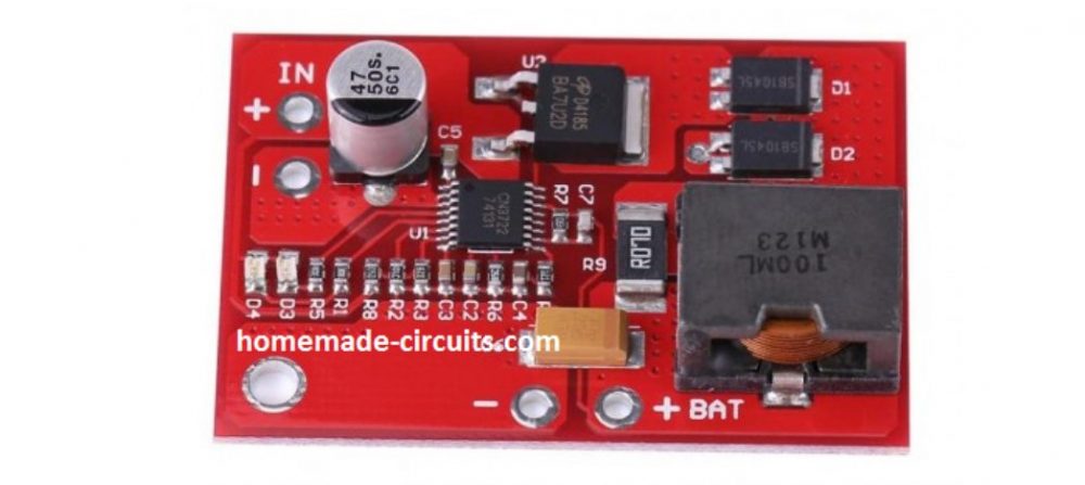
The folks call this an alternator power booster! It enables small gensets support loads bigger than their coils and feel alright with it without yearning!
I disassembled it carefully because D1, R1, R2, C2 and Q1 are obscured inside a glue like paste.
AC IN is from a small 650VA Generating set which is normally incapable of powering the connected loads.
The diode polarity and the value is not certain but this is its place in the circuit. It got broken while dismantling the glued circuit.
Q1 couldn't be traced either because the print was scraped of by the manufacture.Only its pin#1 and pin#3 responded to the DMM, it read zero like a dead diode, pin#2 does not read with any other pin at all. Pin#4 which is the tab is also unconnected.....just cannot figure out the device or its specs.
The diode D1 is blue in color, small glass type.
Solving the Circuit Request
Dear Michael,
It looks like an AC voltage booster circuit to me. Q1 is probably a power triac, the diode might be a diac DB-3, I am assuming this since it's small glass type and blue in color.
I would be addressing this circuit in my blog very soon....kindly stay tuned for the updates in my blog.
Thanks and Regards.
Circuit Explanation
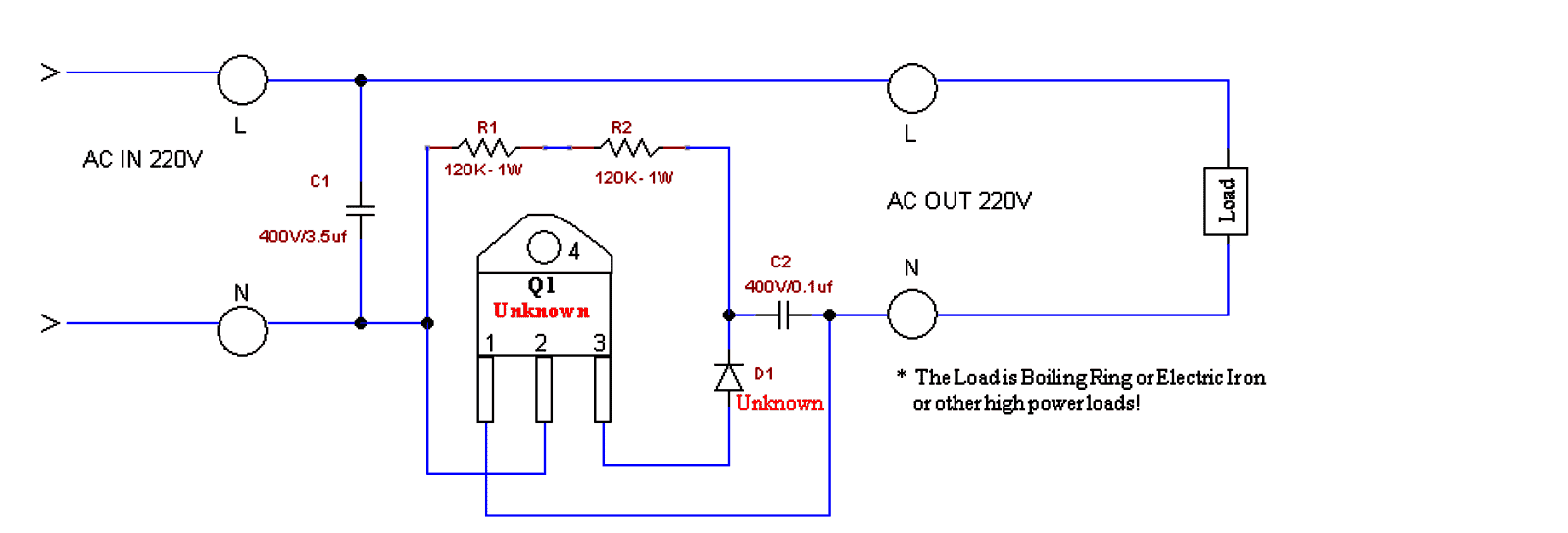
This circuit is a simple AC voltage booster designed for supplying boosted voltage to high-power resistive loads like electric irons or boiling rings. Here's how it works:
Working Principle:
Capacitive Voltage Divider (C1)
The capacitor C1 (3.5µF, 400V) works like a reactive voltage dropper to provide a phase-shifted voltage for triggering the TRIAC (Q1).
It limits the current flowing into the gate of the TRIAC.
Gate Drive for the TRIAC (Q1)
Resistors R1 and R2 (120K, 1W each) form a voltage divider network which ensures a controlled gate drive for Q1.
The combination of D1 (Unknown, but likely a Diac) and C2 (0.1µF, 400V) creates a triggering delay, which allows phase control of the AC waveform.
Switching Action of TRIAC (Q1)
The TRIAC remains off until the breakover (firing) voltage of D1 (could be a Diac like for example a DB3) is reached.
When this happens then the D1 conducts, which sends a sharp pulse to the gate of Q1, turning it on.
The TRIAC then conducts ON, allowing the AC power to reach the load.
Voltage Boosting Mechanism
The phase angle of TRIAC conduction is controlled, which modifies the effective RMS voltage applied to the load.
By partially delaying the triac conduction, the circuit makes it possible to increase the peak voltage for the load.
The increase of the voltage across the load is achieved by extending the conduction duration of the AC cycle.
Main Features:
It Increases output voltage above input voltage (may not bee a true step-up transformer action but rather a phase-controlled voltage boost type).
It will Work effectively with resistive loads (boiling rings, irons, etc.).
This concept Uses phase angle control to regulate output power.
Capacitor C1 is a crucial component which helps to boost the voltage by acting as a reactive impedance.
Limitations:
This design is Not suitable for powering inductive loads (motors, transformers).
Here, the Voltage boost depends on the load resistance and the phase angle.
It Can create harmonics and waveform distortion in the AC supply line of the grid.
Mains Voltage Booster using Two Capacitors and Two Diodes
The above concept can also be implemented with the following circuit which is simpler than the above and is also a lot cheaper.
The capacitor ratings may be modified and experimented with as per the load, and individual preferences.
However this circuit can be used only for heater applications such as irons, heaters, geysers, ovens, toasters, blowers, dryers, hot air gun etc.
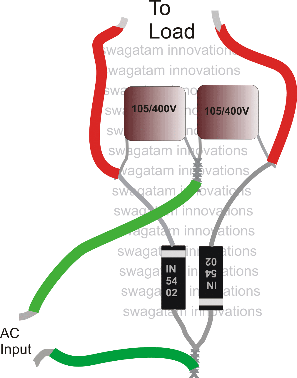
Please use 1N5408 diodes instead of 1N5402, mistakenly shown in the above diagram.

Questions & Answers
Good day our mentor, I will need some ideas on the dc motor to roll wind generator and give me some voltage I can make use of as a project. Then I have some pictures to send that can help for better narration for me, I don’t know how the pictures can get across to you.
Hello Adebanji,
Can you please post your question under the following article, we can further discuss it there:
https://www.homemade-circuits.com/simplest-windmill-generator-circuit/
hello sir , the number of triac pls
Waliyu,
It can be any 16 amp 600V triac
Hi Swagatam, pls need ur ideas on wind turbine generator, can I use dc motor to run it?
Hi Adebanji, yes you can use DC motor as the generator, it is perfectly suitable for windmill applications.
I have an racing mini alternator that outputs 18VAC, is it possible to boost the output to approx.. 35VAC then to convert to DC current for charging a 24V battery system?
No need to boost the AC, you can boost the DC created from 18V AC. After rectification and filtration, the 18V AC will become 18 * 1.41 = 25.38V which is still lower than 28V required for charging the 24V battery.
So you can construct a boost converter using the information provided in the following article, for converting the 25V to 28V DC:
https://www.homemade-circuits.com/how-to-make-simple-boost-converter-circuits/
Hello Engineer M. Swagatam
I assembled the Small generator Alternator Power Boosting Circuit successfully as you demystified it missing parts and circuit diagram to be and it works.
It does not multiply voltage. It is still 220VAC in 220VAC out.
I used A pressing Iron of over 1600Watts to test assembled device and it powered the load using my 650W gasoline Gen.
What I want to know now is How to increase the Wattage Capacity of the device.
Would I need to double or Triple e.t.c the TRIAC and or Capacitor and or increase the Resistors Resistance and or Wattage etc.?
Please reply.
Thank you Sir.
Thank you Dare, for updating the results, it sounds great!
To increase the power, you can try increasing the 3.5uF value capacitor to a higher level, and increase the current handling capacity of the triac also, rest everything can be as is…
Tank you for the Prompt Reply. Can I just Double the Triac thereby connect it Pins in Parallel?
I don’t think that will work, you will have to use a single high power triac, such as the BTA41/600 or similar.
Sir. Can booster circuit power AC motor of 750watts from supply of 500watts?
Hello Umar, sorry, that’s impossible on this planet no matter which circuit you use.
Please do you have a booster for the air conditioner
Sorry, I do not have a booster circuit for air conditioner…
OK sir, but can this Ac booster helps in reducing the current been drawn from the prepaid meter
No, this booster is not a power saver device, it is simply to boost a low voltage AC mains into a higher level DC voltage.
Sir, can this circuit power DC motor of same capacity both voltage and power.
Hello King, yes it can power a DC motor, just add a 100uF/1000V capacitor across the motor wires.
Thanks for the response sir, pls I want the fan be controlled by variable resistor so I can decide the speed I like, in this regard I will love have a circuit that has variable resistor sir.
Thanks for the support.
Adebanji, in the previous voltage regulator diagram which I shared, just replace the zener diode with 10k potentiometer, which can be then used to control the motor speed
Good afternoon sir,
Pls there is another project I am working on now I believe later I can come back on the previous project called voltage booster.
Now I designed a project to control the speed of one radiator fan with 30volt dc and as we all know the actual voltage for the fan is 12v dc, so all transistor used when i control the speed are used to have high temperature and blow up.
Pls what can I do? Can you help get another cct for the project?
Hello Adebanji,
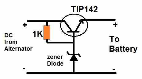
If your fan is 12V then you can stepdown the 30 V to 12V using a transistor regulator circuit, as shown below:
For the zener diode you can use a 13V zener to get around 12V at the output
Dear swagatam,
I have tried your own project in fact I spent time on it but the result I expect I didn’t get it at all.
I use pressing Iron it didn’t work I also used 6a4 diode: 400v 6a , I moved further to use 10a10 diode but its same result.
Pls sir what can I do?
Also you promised to go through the first circuit maybe I should wait for you till you be ready to work on it sir. I remain yours, Thanks.
Hi Adebanji,
Which capacitor did you use in the second circuit? The capacitors are the main elements for boosting the voltage. For your 1400 watt load the capacitors must be rated at least at around 100uF 400V or 630V, and they must be non-polar.
You can initially try using 1uF/400V capacitors and test the heating on your 25 watt soldering iron, you will find the iron becoming red hot due to the boosted voltage.
I really really love you sir. Thank
Kudos ? to our able engineer ? swagatam, I have worked on both circuit but the second one performed well even over performed, I appreciate your effort and concern particularly your response to the questions raised, thanks so much sir. Please ? I need to ask this question, pls like you advised that I can use it
with 1400watts heater, pls what and what can i use? Like the value of components to use. Like value for diode and capacitors. Thanks.
Thank you so much Adebanji, I am glad you could get the desired results from the second circuit.
You can definitely use it with a 1400 watt heater by appropriately upgrading the capacitor and the diode values.
For the diodes you can use 6A4 diodes and for the capacitors you can try 100uF/400V each, they must be non-polar type for best results.
However, please note that if your input power is same as 1400 watts or less then this circuit will not work, in fact no booster circuit will work in that situation.
I have not get feed back from you sir since I made the comment.
Sorry Adebanji, here’s the answer to your comment.
Yes you can use the second circuit for your 1400 watt heater, but you will have to increase the uF values of the capacitors and the power rating of the diodes accordingly to handle the 1400 watt power.
Well done sir, I want to ask if I design this second cct can it be used to power heater, 1400w pressing iron etc, with the explained connections?
Sir,now in the market of nigers the same power booster device (first circuit) has been upgraded to 10000w. Also it’s just performing as they say…… Pl sir why can’t you do something to solve this mystery. It’s a fact that it works well. Further it’s supporting deep freezer and all appliances.
please I need a simple electrical circuit to boost up 30v ac to 240v ac for my electronics appliances at home.
I’m suffering from a very bad low voltage in my area.
pls include the details of the electronic components used and if possible pictorial diagram along side with the circuit diagram.
thanks
what’s the current rating you are supposed to connect?. If higher the current rating it’s very much impossible……! on using 2 nd circuit you lag current.
The current capacity can be increased by appropriately increasing the value of the capacitors and the current rating of the diodes.
You can try the second circuit from the following article to fulfill your requirement. If you are new to electronics then you must first learn all the basics, and only then attempt this circuit.
https://www.homemade-circuits.com/modified-sine-wave-inverter-circuit-2/
Is there any Write up for this project???
What voltage can this produce as output???
What are the pure components used for this project, should incase we want to develop more on it???
Unfortunately there’s no write up for the first circuit. I can provide more details about the second circuit if required.
Regards.sir. With the circuit power booster can we connect lighting loads. Have you developed any thing like this sir. If so pl update me.
Hi Raja, I have tested the last circuit with my soldering iron and it became red hot within a minute. So if it works with a soldering iron then it should work with lights also, provided the light is an incandescent type.
How to make booster for generator
Hi i am a final year, student of electrical and electronic engineering department, my project topic is Ac to Ac based power booster range from 500watt, to 1500watt.
AC to AC power booster can be built only through transformers.
And a 500 watt to 1500 watt power can never happen because power can never be boosted. Either current or voltage can be boosted.