The main technical function of the proposed voltage regulator is voltage stabilization. It is capable of stabilizing an input voltage ranging from 0 to 600 Vdc to an output voltage ranging from 100 to 560 Vdc, with a maximum current of 800 mAdc and maximum power dissipation of 100 W. The unit also exhibits good stability, with a stability of less than 0.1% after 15 minutes of constant input voltage, and a rejection of input ripple greater than 60 dB. By Atul Shah
Often relegated to the status of a neglected or poorly studied 'add-on component' due to lack of interest, the power supply of an electronic circuit can be a source of many disappointments. The following article reminds us of some fundamental points and proposes the designing of a versatile 600 Vdc high voltage regulator module.
The main characteristics of a power supply are the required 'voltage' and 'power', internal stability under variable load, drift over time, and noise rejection.
Power supply
The voltage and current data are quickly fixed according to the demand of the circuit. The internal impedance, on which load stability, time stability, and noise rejection depend, is often a characteristic suffered by the circuit design.
For example, a 30W class AB2 stereo tube amplifier can easily see its current vary between 100mA and 400mA. The high voltage, rectified and filtered by a "choke" coil, will see its voltage drop by several tens of volts, especially if rectified using a valve.
This means that the power supply collapses at the moment when your amplifier needs it the most! The internal resistance of a power supply represents a major key, especially as the voltage is higher.
Any passionate amateur has already experienced its effects, such as "motor boating," an oscillation that results in a slow pulsation that sounds like a boat motor noise in the speakers.
This instability is mainly caused by the power supply's internal resistance being too high.
Note also that this phenomenon is influenced by too much feedback and circuits that go too "low" in frequency.
Our study Regularly confronted with the problems described above, we have developed a high-voltage stabilizer module based on the circuit that we use in many of our projects.
With small dimensions (80 x 40 mm), it fits into most designs. Furthermore, it allows for the elimination of the cumbersome filtering choke. It can be used for the universal stabilization of any voltage between 100Vdc and 600Vdc.
Circuit Description
The 600V regulator circuit module is inserted between the ballast capacitor and the load as shown below.
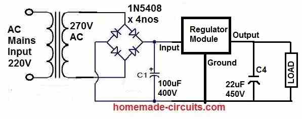
Rectification and electrolytic capacitors are external. Only four connections are required: the input and its return, the output, and its return. The two returns are connected to the floating ground of the module.
The voltage stabilization is achieved at the collector of Q1. The 10.7 V present at the two zener diode terminals biases the emitter of the PNP transistor to 10V, and a stable current of 1mA flows through resistor R2 of 10kΩ. This same current develops a stable voltage across resistors R3, R4, and P1 at the collector.
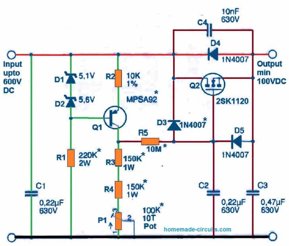
This voltage is filtered by the R5-C2 filter and biases the gate of the MOS transistor/Q2. The output voltage is taken from the "source" of Q2.
Note that the Vce voltage of Q1 can vary considerably. In fact, the input voltage is not filtered and can have a ripple of several tens of volts. Additionally, this voltage varies according to the vagaries of the sector and the variations in the output load current.
The voltages indicated on the diagram are those expected for an input voltage of 380V to 450V and a stable output voltage between 300V and 400V.
As the module accepts many other values, here are some indications to define certain components. The values of D1, D2, and R2 are invariable. The capacitor values are not critical as long as the same orders of magnitude and service voltages are respected.
Components marked with an asterisk can be changed according to needs. First of all, to ensure proper stabilization, it is imperative to maintain an input voltage that is about 20 volts higher than the output voltage. R1 must impose a current of 2mA to 3mA in the zener diodes.
Resistors R3, R4, and potentiometer P1 are calculated to develop the desired voltage based on the 1mA current that flows through them.
The PNP/Q1 transistor is an MPSA92 that supports 300V.
It can be replaced by a 2N5401 if Vce does not exceed 150 V. The R5-C2 filter allows for a 70 dB rejection of the ripple at 100 Hz, but the high voltage takes about twenty seconds to settle. By replacing R5 with a value of 1 MSS, the voltage settles immediately and the ripple rejection is still 50 dB.
It should be noted that with a typical choke, the attenuation of residual ripple is about 20 dB. Additionally, the choke adds a resistance of several tens of ohms to the internal resistance of the power supply.
Finally, the chosen transistor Q2 is a 2SK1120 from Toshiba. We chose this one because our BUZ305 became unavailable.
The 2SK1120's TO-247 package has two advantages:
- The length of the leads is 20 mm (15 mm for the BUZ305)
- The top surface and the mounting hole are insulated, eliminating the need for an insulating sleeve.
However, it is possible to replace it with a 2SK1489 with a maximum power dissipation of 200 W.
The regulator circuit module operates from an input voltage of around a hundred volts that can be raised to a maximum of 600 Vdc. It must deliver a minimum current of 20 mA and can easily reach 1 A, provided that the MOSFET's dissipation limits are respected.
Heatsink Specifications
The heat sink also has a thermal resistance with respect to ambient air, which can be reduced to very low values by using a fan. These thermal resistances must be taken into account as they cause a shift in the graph towards lower values.
Practical example: suppose the ballast transistor consumes 30 W, is insulated by a 0.85°C/W spacer, and is mounted on a 1°C/W heat sink. The heat sink removes the heat, and the temperature rise will be 30°C, plus the 25°C ambient temperature, totaling 55°C.
The transistor temperature will be even higher, by 25.5°C (30 x 0.85), due to the thermal resistance of the spacer, making it 80.5°C. This is still within the safe range, as the maximum allowable dissipation at 85°C is still 80 W.
Different mechanical mounting configurations have been provided. The first is mounting on an aluminum block of 40 x 80 x 6 mm with a spacer for integration into a closed chassis. If the aluminum block is screwed onto the chassis or an external heat sink, the module can dissipate up to 40 watts, which is more than enough for most audio applications.
The second possibility is external mounting. For this purpose, the module is placed on an aluminum base of 84 x 70 x 5 mm, fixed to the chassis, and protected by a transformer cover of type E184. The allowable dissipation is also around 40 watts.
The third option involves mounting the transistor without a spacer. The electrical insulation will be between the aluminum block at the input HT potential and the heat sink.
The thermal interface is located between the 40 x 80 mm aluminum block, which has an area of 32 cm², and the heat sink.
The thermal resistance of the insulation will be around 0.08°C/W. With a fan-assisted heat sink, it is possible to dissipate 120 watts, which is mainly applicable for laboratory power supplies.
Use & Technical Specifications
This 600V high voltage circuit module integrates all the essential elements for stabilization and can be mounted far from the voltage source and its use.
All tests have been carried out with 50 cm leads between the ballast capacitor and the module, as well as between the module and the loads, without any instability problems. The module's own internal resistance is around 5 Ω at constant input voltage.
However, this resistance is influenced by the transformer's power. For our test, we use a 110 VA transformer, a bridge rectifier, and a 100 pF buffer capacitor. The internal resistance of the entire setup is then established at 13 Ω.
When integrating the module into a design, it is advisable, in the first instance, to protect the module with a quick fuse and a hundred ohms resistor to ensure that the output current is limited to an acceptable value.
With such a low internal resistance, any short circuit in the output line will be fatal to the ballast. The stability of the output voltage is measured by varying the input voltage. A variation of 330 Vdc to 400 Vdc at the buffer capacitor, equivalent to a ±10% mains variation, produces a 2 Vdc output variation.
After stabilization for ten minutes with a constant input voltage, the output voltage remains within a range of 0.1%.
The rejection rate is the ratio between the input ripple voltage and the output voltage. For a current consumption of 200 mA, the input ripple voltage is 6 Vac, and the output ripple is 2 mVac, resulting in a ratio of 3000 or 70 dB.
The table of technical specifications shown below reflects the various possibilities in voltages and currents. We must not forget that the values of the voltages, currents, and powers are intimately linked by the relation:
(Vin - Vout) x I = P.
| Technical Characteristics | Specifications |
|---|---|
| Maximum Input Voltage (*) | 600 Vdc |
| Output Voltage (`) | 100 - 560 Vdc |
| Current (*) | 0 - 800 mAdc |
| Maximum Power Dissipation (*) | 100 W |
| Stability for Uin +/- 5% | 41-0.5% |
| Stability for constant Uin | <0.1% after 15 min |
| Ripple Rejection (*) | >60 dB |
| Residual Ripple (I=250 mAdc) | <3 mVac |
| Static Internal Resistance | <10 Ω |
| Internal Impedance | >100 Hz <10 Ω |
| Dimensions (LxWxH) | 80 x 40 x 40 mm |
| Weight | 100 g |



Questions & Answers
muito bom o seu circuito vou utlizalo como fonte em meus amplificadores valvulados.muito obrigado e parabens por seu trabalho.
You are most welcome! Glad you found it useful! Let me know if you have any further questions or doubts!
bonjour mr swagatam je realisé un circuit qui permet de transformé une tension 220Vac a une tension 127Vcc 1A est ce que vous pouvez m’aidé pour le realisé merci d’avance
Hello Mr. Swagatam, I want to create a circuit that converts 220V AC to 127V DC at 1A. Can you help me with its design? Thank you in advance.
Hello Charaf,
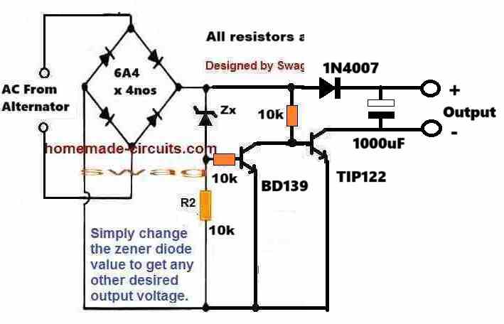
You can try the following concept:
Just make sure to include a 22uF/400V PPC capacitor in series with the input mains supply.
And replace the BJTs with MJE13005 or equivalent, and use a 150V 1 watt for the zener diode. The resistors must be 2 watt rated.
And also note that this circuit is not isolated from mains AC, so be extremely careful while handling it.
Have a 918W 310V DC motor as generator, I want this to make a 80V constant DC output to charge my bike battery with max amp it produces. since generator cannot provide constant 310 at the time of start so i need variable input from 100-280-310 but need 80V constant output, can i use this circuit to make so?
Hi. Greetings.
I am building a linear rectifier from 120V AC mains input, and after rectifying, the DC output is going up to around 160V DC because of the filter capacitors.
Now, I want to reduce that output voltage down to 100V DC, with 1.5 amps max current, and also I want the output voltage to stay stable, without big fluctuations.
Can someone help or guide me how to do this?
Thanks a lot.
Hi, definitely you can achieve it using an SMPS circuit, if you want it to be without any heat dissipation:
https://www.homemade-circuits.com/smps-transformer-calculator-2/
If some heat dissipation is OK, then you can try the following simple circuit, please replace the transistor with an MJE13005:
I would rather recommend the second design from the following article, because it is a tested circuit:
https://www.homemade-circuits.com/0-300v-variable-voltage-current/
can it handle 5-10amp since my generator is 918 watt and if dropped to 80V then amp can be roughly 10+. is it fine to handle such? you mentioned 100mA max in output.
Current output can be increased by modifying the R2 value in the previous circuit, and also by changing the MOSFET accordingly.
R2 = 0.6 / Max Current Output
However, stepping down 310V to 80V with a linear regulator would cause huge dissipation and heat generation by the MOSFET.
In that case I would recommend using a buck converter circuit instead.
Yes, buck will be my 2nd project however this time I’m planning to use LM2596 buck to replace your transistor feedback since there need 10.4 v as per your design, hopefully it will work. I’m just concern on the amp output. am using 40T321 IGBT even higher than that, lets see.. do you mind if I get your mail address, i need to be connected with you, mine is kazinuraalahi@gmail.com
There’s no feedback transistor in my previously linked diagram. The BC547 is used as a current controller, to limit the output current to the load.
I am not sure how the LM2596 buck converter can be used in this circuit to minimize dissipation, it cannot be used according to me.
A buck converter designed to handle 350V – 80V must be connected directly to the input 300V DC source for ensuring maximum output efficiency.
You can feel free to discuss the issue here, I will try my best to solve it for you…
Hi- I’m sorry, i was talking on the earlier design not this. anyways, would you please discuss how this circuit can stable the output to 80V dc with 10A current regardless the input between 100-310V, I’m really confused. 547 is not capable in handling such current. i just simulated earlier circuit, at the output giving 250-270V dc and the P1 V/R not functioning any. I’ll simulate this also lets see..
The BC547 does not handle the current directly. When current exceeds the set limit, the BC547 conducts and short circuits the MOSFET gate/source to stabilize the output.
The circuit is tested practically by me and it works perfectly. Please do not simulate, instead understand the functioning, and build it practically…. because as you can see your simulation is giving wrong results.
I will try to design the buck converter for the 300V to 80V DC, and let you know.
well thank you so much. ill wait for that buck converter. As i understood from the given circuit- it is driving gate voltage with voltage divider using 500K pot which will vary depending on input voltage meaning if input varies then gate voltage will vary and output will vary accordingly thus providing a variable voltage in output, not fixed. I need fixed output 80V, hope it makes you understand the scenario.
In the previous circuit the output can be fixed by simply adding a 85V zener diode between MOSFET gate and ground,, but the MOSFET will heat up a lot at over 100V input. The MOSFET can be safeguarded by adding adequate heatsink to it…if that is OK then you can try the previous circuit…
thank you so much for your time. ill be in touch with you, see you.
Sure, no problem!
Hi- in my circuit if it gives output as much it gets in gate voltage. Meaning if gate voltage is 8 it gives 8, if 80 it gives 80 using linier voltage. Now I need a simple circuit which will provide stable 80v from 12v, please help. I tried to use pwm of booster circuit from market but MOSFET gets super hot and damaged.
Hi, If the circuit is not regulating the input voltage then I think your MOSFET could be malfunctioning, or there may be some other fault in the circuit.

PWM cannot be used for getting a constant DC output, because then the output peak voltage will be always equal to the input voltage peak.
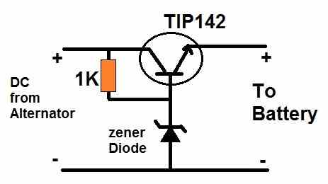
You can try the following simple design, the transistor must be relaced with a MJE13005 transistor.
The zener diode value must be 1V higher than the desired output voltage across the emitter and ground:
thank you, let me try with this.
OK, no problem!
Hi- i have a problem, input from 40-140V variable ac to 82V constant regulated DC. can you please help in providing some circuit to solve this.
Please specify the required maximum current output also, I will try to figure it out…
Hi-10A max. Basically need one buck converter with input range 40-140V DC and output 82V please.
OK, I have explained the entire procedure in the following article. You just have to recalculate the inductor value by replacing the parameters in the given equations:
https://www.homemade-circuits.com/calculating-inductor-value-in-smps/
For the transistors, just make sure all are rated at above 150V, and the TIP127 is replaced with a 200V 20 amp power transistor
Hi- BC546, C E voltage 50 max, how can it handle 140V DC input to provide 6V using Zener to 555, am confused. output can get from inductor other end and high voltage filter needed. this astable timer used as PWM?
Yes, that’s why I suggested you to change all the BJTs and make sure they are rated at above 150V. Instead of 6V zener you an use a 12V zener.
I did not understand what you meant by “high voltage filter needed”
The 555 is used as a PWM astable with duty cycle control.
Hello Swagatam.
Thank you for the presentation of this configurable circuit and the functional description.
There are similar suggestions, but I haven’t seen it like this before. Simple and yet very effective.
As a radio amateur I was looking for an anode voltage stabilization for the preamplifier of a 630m tube power amplifier. The simulation in LTSpice for 250V/60mA with IRF820 and 2N5401 looks excellent.
Thank you very much!
Olaf, DL4SA
Thank you Olaf, glad you found the above post useful.
I hope it works for you.
If you have any issues with the circuit, please let me know.
What similar ic cd4035 pwm 3 phase
Sorry, there’s no equivalent for this IC.