The train sound simulator circuit is an electronic circuit that generates a realistic sound that mimics the sound of a train moving on tracks. The circuit is designed to be integrated into a model train set or layout to add to the overall realism of the scene. The sound is produced using a combination of oscillators, amplifiers, and filters, and is controlled by a series of counters and timers. The circuit can be adjusted to produce different train sounds, such as a steam engine or a diesel locomotive, by varying the frequency and amplitude of the generated sounds.
The role of this train sound simulator is to imitate the characteristic sound of wagon axles passing over rail joints. This will satisfy all model railway enthusiasts.
Most railway tracks are made up of a series of "rails" that can reach several hundred meters in length, connected to each other by rail joints. To allow for the expansion of the rails, a gap of a few millimeters is provided at the joint.
When the axles pass over these rail joints, a periodic and very characteristic noise is heard that accompanies the passage of the train. Depending on the type of rolling stock, the periodic structure of the emitted noise differs.
The proposed setup generates this same noise by distinguishing between passenger cars with bogies and "freight" rolling stock with axles.
Power supply
The power supply requires little comment. It follows the classic chain from the transformer to the output of the 7809 regulator, via the bridge rectifier. C1 provides initial filtering.
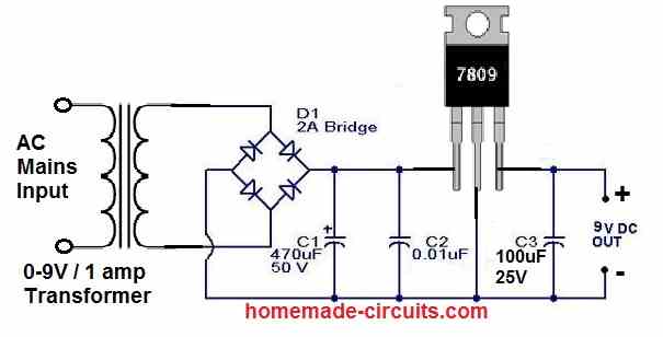
The voltage, stabilized at 9V by the regulator, benefits from additional filtering provided by C2, while decoupling is ensured by C3.
Time base
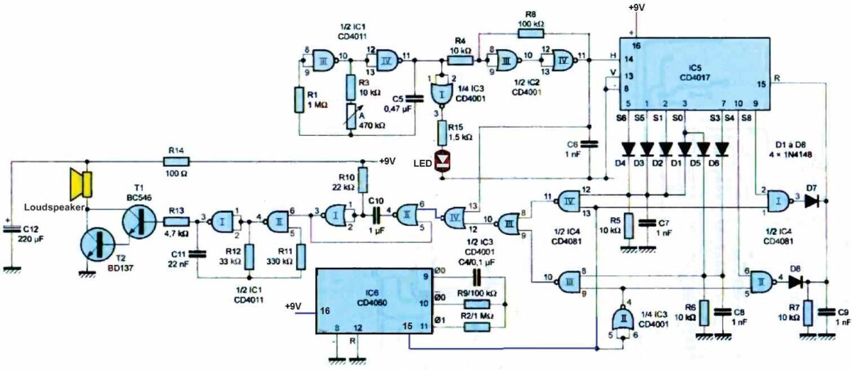
The NAND gates (III) and (IV) of 1C1 form an astable oscillator that delivers a square wave signal whose period depends on the angular position of the slider of the adjustable A.
This can vary from a few milliseconds to nearly 200 ms, and it constitutes the time base of the noisemaker. The LED L, by its blinking at the same rate, indicates the operation of the oscillator.
The NOR gates (III) and (IV) of IC2, with the peripheral resistors R4 and R8, act as a Schmitt trigger to give the rising and falling edges of the signal a more vertical shape, thanks to an acceleration of the switching speed of the oscillator gates.
Periodic noise structure
The reference circuit IC5 is a decimal counter advancing one step at the rhythm of the rising edges present on its "Clock" input (pin 14).
The "high" state then moves from output Sn to output Sn+1. As for the used Sn outputs, two groups of diodes with common cathodes can be distinguished:
- the group D1, D2, D3 and D4 which correspond respectively to outputs SO, S1, S5 and S6
- the group D5 and D6 corresponding to outputs SO and S3. A relational similarity can be noted between these groupings and the succession of axles of different types of trailer equipment:
- passenger cars for the first group
- "freight" wagons for the second.
Alternative selection of groups
IC6 is a counter with fourteen binary stages connected in cascade. Its internal time base "t" is determined by the values of R9 and C4. It is approximately 22 ms in the present case.
On each Qn output, a square wave signal is obtained whose period T is calculated using the relationship Tn = t x 2^n.
Thus, on the 010 output, the period of the square wave signal delivered is approximately 22 s. On this output, an uninterrupted alternation of "high states" and "low states" of the same duration is recorded.
The 010 output is connected to one of the two inputs of gates AND (I) and (IV) of IC4. It is also connected, but after inversion by the NOR gate (II) of IC3, to one of the two inputs of gates AND (II) and (III) of IC4.
The following operating principle results from these connections:
For a duration of 11 s, the output of gate AND (IV) of IC4 presents on its output the logical level present on the cathodes of the diodes in the first group (SO, Si, S5 and S6 of IC5).
When counter IC5 reaches position S8, it is reset to zero and continues its cycle. During this time, the output of gate AND (III) of IC4 remains in the "low" state.
During the next 11 s, the output of gate AND (III) of IC4 presents the logical level of the cathodes of the diodes in the second group (SO and S3).
In this case, it is position S4 of counter IC5 that ensures its reset to zero. The output of gate AND (IV) of IC4 remains in the "low" state.
This alternating cycle continues endlessly. Table A summarizes this operation.
Generation of noise
For each positive pulse from flip-flop IC2, the NAND oscillator (I) and (II) of IC1 comes into action. It delivers on its output a square wave signal characterized by a period of approximately 1.5 ms, which corresponds to a frequency of 625 Hz.
This is a so-called musical frequency. It is particularly audible. Since its duration is short, the corresponding noise is very "dry".
The Darlington formed by transistors T1 and T2 provides the necessary amplification. The loudspeaker winding is inserted into the circuit of the common collectors of the transistors.
Between two consecutive noises, capacitor C12 charges through R14. It discharges when the noise is turned off to give it an extra power boost without altering the power supply potential of the circuit.
Circuit Diagram
Implementation
There are no special remarks regarding the implementation of this train sound simulator circuit board.
Once the components are in place and after a final check of the correct orientation of the polarized elements, testing can be carried out directly.
The only possible adjustment is to act on the adjustable slider. By turning it clockwise, the period of the base time decreases. This simulates an increased speed of the railway convoy.
Conclusion:
The train sound simulator circuit generates a periodic noise that simulates the sound of a train passing by.
The circuit consists of several components, including a counter, oscillators, transistors, capacitors, and a speaker. The counter counts clock pulses and activates the oscillators to produce a square wave with a frequency of 625 Hz.
The square wave is amplified by a Darlington pair of transistors and fed into the speaker to generate the train sound.
A capacitor charges and discharges between the noise pulses to add a power boost to the sound. The only adjustment necessary is to adjust the adjustable resistor to vary the train's speed.

Questions & Answers
I like this train sound simulator. But I see a discrepancy in the schematic.
The CD4081 is a quad 2-input AND gate.
But referring to the schematic notation “1/2 IC4 CD4081” in two places …
… the gates are drawn as NAND instead of AND.
So should those four gates be drawn as AND (CD4081) ?
Or are they truly NAND gates, as drawn (CD4011) ?
Hi, thanks for pointing out the mistake, and indeed looks like a drawing error. Those 4081 gate symbols shouldn’t be having the small round heads in the front, which were probably mistakenly put, please ignore the symbol, and consider only the labeling.