• Skip to main content
  • Skip to primary sidebar

Homemade Circuit Projects

Need circuit help? Post them in the comments! I've answered over 50,000!

Blog | Categories | About | Hire Me | Contact | Calculators-online
You are here: Home / Inverter Circuits / 2 Cool 50 Watt Inverter Circuits for Students and Hobbyists

2 Cool 50 Watt Inverter Circuits for Students and Hobbyists

Last Updated on January 19, 2025 by Swagatam 170 Comments

A 50 watt inverter circuit might look quite trivial, but it can serve some useful purposes to you. When outdoors, this small power house can be used for operating small electronic gadgets, soldering iron, table top radios, incandescent lights, fans etc.

Table of Contents
  • Design#1: How it Works
    • Parts Required
    • Testing and Setting Up the Circuit
    • Design#2: 50 Watt Mosfet Inverter Circuit
    • Parts List
      • Video showing the Testing process of the 50 watt inverter circuit:

Let’s learn 2 homemade 50 watt inverter circuit designs, beginning with a brief description regarding the circuit diagram and its functioning:

Design#1: How it Works

The first 50 W circuit may be understood with the following points:

Referring to the figure below, transistors T1 and T2 along with the other R1, R2, R3 R4, C1 and C2 together form a simple astable multivibrator (AMV) circuit.
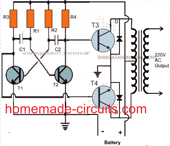
50 Watt Inverter Circuit Diagram using BJTs

A transistor multivibrator circuit basically is composed of two symmetrical half stages, here its formed by the left and the right hand side transistor stages which conduct in tandem or in simple words the left and the right stages conduct alternately in a kind of a perpetual “motion”, generating a continuous flip flop action.

The above action is responsible of creating the required oscillations for our inverter circuit. The frequency of the oscillation is directly proportional to the values of the capacitors or/and the resistors at the base of each transistor.

Lowering the values of the capacitors increases the frequency while increasing the values of the resistors decreases the frequency and vice versa. Here the values are chosen so as to produce a stable frequency of 50 Hz.

Readers, who wish to alter the frequency to 60 Hz, may easily do it by just changing the capacitor values appropriately.

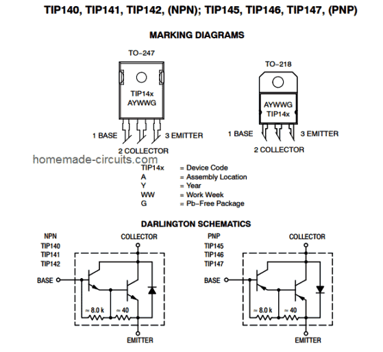
Transistors T3 and T4 are placed at the two output arms of the AMV circuit. These are high gain; high current Darlington paired transistors, used as the output devices for the present configuration.

The frequency from the AMV is fed to the base of T3 and T4 alternately which in turn switch the transformer secondary winding, dumping the entire battery power in the transformer winding.

This results in a fast magnetic induction switching across the transformer windings, resulting the required the mains voltage at the output of the transformer.

Parts Required

 You will require the following components for making this 50 watt homemade inverter circuit:

ComponentValue
R1, R2100K
R3, R4330 Ohms
R5, R6470 Ohms, 2 Watt
R7, R822 Ohms, 5 Watt
C1, C20.22 uF, Ceramic Disc
D1, D21N5402 or 1N5408
T1, T28050
T3, T4TIP142
TIP142 pinout specifications

General purpose PCB = cut into the desired size, approximately 5 by 4 inches should suffice.

Battery: 12 volts, Current not less than 10 AH.

Transformer = 9 – 0 – 9 volts, 5 Amps, Output winding may be 220 V or 120 volts as per your country specifications

Sundries: Metallic box, fuse holder, connecting cords, sockets etc

Testing and Setting Up the Circuit

 After you finish making the above explained simple inverter circuit, you may do the testing of the unit in the following manner:

Initially do not connect the transformer or battery to the circuit.

Using a small DC power supply power the circuit.
If everything is done rightly, the circuit should start oscillating at the rated frequency of 50 Hz.

You can check this by connecting the prods of a frequency meter across T3’s or T4’s collector and the ground. The positive of the prod should go to the collector of the transistor.

If you don’t own a frequency meter, never mind, you do a rough checking by connecting a headphone pin across the above explained terminals of the circuit. If you hear a loud humming sound, will prove that your circuit is generating the required frequency output.

Now it’s time to integrate the battery and the transformer to the above circuit.

Connect everything as shown in the figure.

Connect a 40 watt incandescent lamp at the output of the transformer. And switch ON the battery to the circuit.

The bulb will immediately come ON brightly…..your homemade 50 watt inverter is ready and may be used as desired by for powering many small appliances whenever required.

Design#2: 50 Watt Mosfet Inverter Circuit

The circuit explained above involved power transistors now let's see how the same concept may be utilized with mosfets making the configuration much easier and straightforward, yet more robust and powerful.

Rest of the stages are pretty much the same, in the earlier circuit we saw the involvement of  a transistor based astable multivibrator for the generation of the required 50 Hz oscillations, here too we have incorporated a transitor operated AMV.

The earlier circuit had a couple of 2N3055 transistors at the output and as we all know driving power transistors efficiently requires proportionate amount of base drive, relative to the load current, because transistors depend on current drive rather than voltage drive, in contrast to mosfets.

Meaning, as the proposed load becomes higher, the base resistance of the relevant output transistor also gets dimensioned accordingly for enabling optimal amount of current to the base of the transistors,

Due to this obligation, in the previous design a additional driver stage had to be incorporated for facilitating better drive current to the 2N3055 transistors.

However when it comes to mosfets, this necessity becomes completely insignificant.

As can be seen in the given diagram, the AMV stage is instantly preceded by the relevant gates of the mosfets, because mosfets have very high input resistance, which means the AMV transistors wouldn't be unnecessarily loaded and therefore the frequency from the AMVwouldn't be distorted due to the integration of the power devices.

The mosfets are alternately switched, which in turn switches the battery voltage/current inside the secondary winding of the transformer.

The output of the transformer gets saturated delivering the expected 220V to the connected loads.
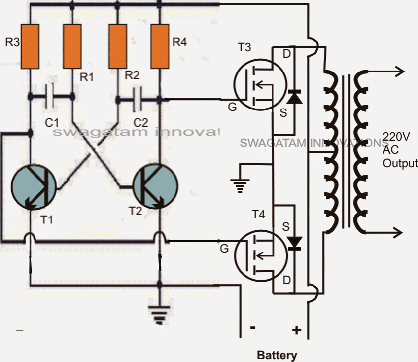
50 Watt Inverter Circuit Diagram using MOSFETs

Parts List

ComponentValue
R1, R227K
R3, R4220 Ohms
C1, C20.47uF/100V, metallized
T1, T2BC547
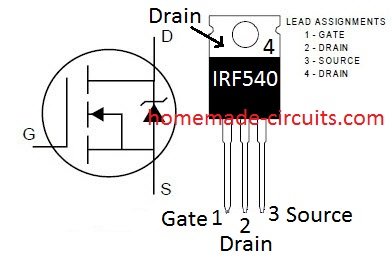
T3, T4Any 30V, 10A N-channel MOSFET or a couple of IRF540
Diodes1N5402 or any 3A rectifier diode


MOSFET IRF540 pinout details

Transformer = 9-0-9V, 8 amp
Battery = 12V,10AH

Video showing the Testing process of the 50 watt inverter circuit:


You'll also like:

  • IC 556 Pure Sine Wave Inverter Circuit
  • inverter batterychargerchangeoverrelaycircuit2 Easy Automatic Inverter/Mains AC Changeover Circuits
  • Automatic Inverter Fan Switch ON while Charging and Inverting Modes
  • 6How to Make a Simple 200 VA, Homemade Power Inverter Circuit – Square Wave Concept

Filed Under: Inverter Circuits Tagged With: Circuits, Cool, Hobbyists, Inverter, Students, Watt

About Swagatam

I am an electronics engineer and doing practical hands-on work from more than 15 years now. Building real circuits, testing them and also making PCB layouts by myself. I really love doing all these things like inventing something new, designing electronics and also helping other people like hobby guys who want to make their own cool circuits at home.

And that is the main reason why I started this website homemade-circuits.com, to share different types of circuit ideas..

If you are having any kind of doubt or question related to circuits then just write down your question in the comment box below, I am like always checking, so I guarantee I will reply you for sure!


Previous Post: « Make a Battery Charger in 15 Minutes
Next Post: Simple PIR LED Lamp Circuit »

Reader Interactions

Questions & Answers

Total Posts: 170
Newest Oldest
way
August 13, 2026 • 1 week ago #211884

hi swag. can you add capacitor to secondary winding to improve sine wave with no problems.

Reply
SwagatamAdmin
August 13, 2026 • 1 week ago #211891

Hi Way, yes that’s very much possible…

Reply
way
August 9, 2026 • 2 weeks ago #211612

hi swag proteus sim produced sinewave o/p 153 volts rms across 1500 ohm load and 53 amps drawn from battery.calculated o/p power at 15watt.would darlington pairs work better

Reply
SwagatamAdmin
August 9, 2026 • 2 weeks ago #211638

Way, Yes, you will actually need two TIP35 in parallel for each channel with 2N2222 replaced with a TIP122.
Better to go with a MOSFET IRZ44N on each channel with adequate heatsinks…

Reply
way
July 30, 2026 • 3 weeks ago #210995

hi swag. what power transistor could i use to increase 50 watt inverter to 100 watt.
alsowhat the best way to test power output of inverter?

Reply
SwagatamAdmin
July 31, 2026 • 3 weeks ago #211046

Hi Way, if you want to use power BJTs for 100 watt, then you will have to replace the output BJTs with Darlington combination of 2N2222 and TIP35…

Reply
way
July 30, 2026 • 3 weeks ago #210962

hi swag
is thier an alternative to the 8050 transistors in the 50 watt inverter circuits?

Reply
SwagatamAdmin
July 30, 2026 • 3 weeks ago #210969

Hey Way,
you can try 2N2222 or BD139 in place of 8050.

Reply
Asikpo Okon
October 8, 2025 • 11 months ago #187903

hello sir, I built the second circuit above, using 50n06 MOSFET , c1815 and ferite transformer but no output at the primary side of the transformer what could have cause it
thanks for responding

Reply
SwagatamAdmin
October 9, 2025 • 11 months ago #187938

Hello Okon, please first check whether your transistor astable circuit is working or not? Disconnect the MOSFETs, and connect an oscilloscope across both the BJTs collector/emitter (one by one) and check the waveform. Make sure it is square wave.
If it is OK, then make a MOSFET tester jig and check if the MOSFETs are good or not, as explained in the following article:
https://www.homemade-circuits.com/how-to-check-mosfet-using-digital/

Reply
john
June 21, 2022 • 4 years ago #128251

re the mosfet inverter. diodes should be fast recovery and the output needs a filter. this has nothing; not even a capacitor and the output will be nasty

Reply
SwagatamAdmin
June 21, 2022 • 4 years ago #128255

The diodes does not need to be fast recovery since the inverters are 50 or 60 Hz rated. You can put a capacitor at the output, no big deal.

Reply
Don Pascual
September 4, 2020 • 6 years ago #81994

I am so happy to find this today. I have been looking for many years for a way to charge cordless phones directly from a DC source and up until now I have found it is not impossible to do without a energy wasting design of 12V to 120V and 120V to 6V inverter and adapter in line. Now since a cordless phone battery will not charge unless the 6 or 9V DC signal from the included AC adapter is pulsing, this means it is not as simply to e.g. look at the output of the transformer as “6V DC” and then simply provide a DC source from a battery (filtered supplies don’t work as it must be a pulsing DC).
Questions:
1) Can I grab a pulsing 6VDC or 9VDC (depending on supply power) by using only one output transistor and tapping onto that output, without the transformer?
2) Have you ever run into a 1:1 or a 1:2 transformer for sale (affordable) that could be used here where the power supplying the phone could be isolated? I know that I could use 2 transformers 6V to 120V and 120V back to 6V but I’m wanting to use the circuit that will be continuously running and powered from a small battery and wish to conserve energy as much as possible.
3) How much of a load would you anticipate that this circuit would draw “unloaded” with a) direct connected with no transformer or b) through a double step up/down transformer setup or c) if I can find a 1:1 or 1:2 wound transformer

Reply
SwagatamAdmin
September 5, 2020 • 6 years ago #82002

Glad you are enjoying the articles.
1) Yes you can grab a pulsing supply, by attaching the intended load between the supply and the drain of one of the MOSFETs.
2) You can easily buy 1:1 transformer from any online store, it is readily available. However, the frequency of the circuit will need to be properly matched with the number of primary turns of the trafo.
3) The idle current consumption of the circuit will a) depend on the resistor at the drain of the other MOSFET. b)/c) will be significantly high compared to without a transformer.

Reply
Mike
May 21, 2020 • 6 years ago #78877

I am building the simpler of the two circuits. Am very new to this sort of thing and have a very simple question before I check out the circuit –
Two of the leads, namely those from the emitters of all 4 transistors are shown as going to ground. I have always understood that ground is the same as the negative lead. Should they be connected to the -ve lead form the 12V battery (I note that the lead from the 8050 transistors does in fact connect with the -ve lead before the ground symbol is shown, but the lead from the two Darlington transistors is not shown so). If this is not the case, where should the connections go?
As a matter of interest, if this is the case, why is it shown the way it is – is this just a convention?

Reply
SwagatamAdmin
May 21, 2020 • 6 years ago #78883

Yes the transistor emitters will go to the negative of the battery, which is the common line for the whole circuit. The negative sign on the battery indicates that it is the opposite of the positive. If you connect the voltmeter oppositely or with wrong polarity across the battery terminals, the meter will show the voltage in negative, and this explains why we have (-) sign on the battery negative terminal.

Reply
Marcelo
September 25, 2019 • 7 years ago #70473

Good morning estimable Swag,
I need a simple inverter to work with 12V / 12Ah battery. I got a small, 12v to 12v12 satellite dish receiver, but I don’t know how many amps (any practical suggestions to know?). Could you get some 60W working with the IRF540?
Thanks

Reply
SwagatamAdmin
September 25, 2019 • 7 years ago #70483

Hi Marcelo,
if the satellite dish receiver is 12V DC then an inverter will not be needed, you can directly power it from the battery, or may be I didn’t understand your requirement correctly.
Anyway for a simple inverter you can try any of the designs I have explained below:

https://www.homemade-circuits.com/7-simple-inverter-circuits/

Reply
Marcelo
September 25, 2019 • 7 years ago #70505

The transformer is from an old receiver.

Reply
SwagatamAdmin
September 26, 2019 • 7 years ago #70514

Please provide its specs.

Reply
Marcelo
November 21, 2019 • 7 years ago #72293

12v-0-12v/2A

Reply
SwagatamAdmin
November 21, 2019 • 7 years ago #72305

You can power the satellite receiver directly from the 12v battery

Reply
amor
January 31, 2019 • 8 years ago #65255

Hi Sir Swag, what i have with me is a 12-0-12, 0-220ac 7amps trafo, its a bit heavy, i want to make a simple inverter
that can power up a fan, a cfl lights, and a led bulb, using a single 12v 7-9ah battery. what do you suggest Sir?
i’m finish with your “20 watt fluorescent tube circuit” thanks to you Sir, but i want more lights with a simple inverter that you can suggest that can also last couple of hours with a single 12v battery. thanks!

Reply
SwagatamAdmin
January 31, 2019 • 8 years ago #65264

Hi Amor, for this you can use an IC 4047 based inverter as given here:

https://www.homemade-circuits.com/2013/06/modifying-4047-ic-inverter-into-sine.html

But using a single 7Ah battery to run so many equipment can drain the battery quickly, and also shorten the life span of the battery!

Reply
youngking
January 23, 2019 • 8 years ago #65130

Good morning sir, pls sir i build this circuit on a bread board yet it didn’t work , the R3 and R4 get bit warm each time i connect the battery . i use 9volt battery the one micro phone normaly use , although i didn’t see the capacitor you mention there in the market , therefore i use 474j capacitor .
i also use head phone to check the frequency yet nothing happen, although i didn’t have frequency meter. pls what could be the fault because i build this accroding ur diagarm

Reply
SwagatamAdmin
January 23, 2019 • 8 years ago #65134

youngking, as you can see it is a very basic circuit, so it has to work and moreover it is a tested design. I would recommend you to first build a basic astable circuit with LEDs as shown in the first diagram from this article and then apply it or the inverter function:

https://www.homemade-circuits.com/2012/01/how-to-make-any-light-strobe-light.html

don’t use VR1, use 100K for the base resistors initially

Reply
youngking
January 7, 2019 • 8 years ago #64893

good day sir , sir this second circuit that uses mosfet , the capacitor you mention as 0.47uf/100v metalized . 474j/100v was wirtten on it but they told me it is the one you mention in your diagram pls clear my doubt i ‘m confuse.

Reply
SwagatamAdmin
January 8, 2019 • 8 years ago #64897

the capacitor which your shopkeeper has suggested is OK, and will work without issues

Reply
youngking
December 24, 2018 • 8 years ago #64705

thank you for clearing by doubt

Reply
youngking
December 20, 2018 • 8 years ago #64651

you said that the battery should be 7 ah does it mean that higher ah will not work. what if i use 12-0-12 transformer with higher amper will it still go

Reply
SwagatamAdmin
December 21, 2018 • 8 years ago #64659

any desired battery with any Ah rating can be used, but the transformer and the mosfets will also need to be upgraded accordingly.

Reply
youngking
December 20, 2018 • 8 years ago #64650

sir is about the first circuit that uses transistor, accroding to what you said.The earlier circuit had a couple of 2N3055 transistors at the output and as we all know driving power transistors efficiently requires proportionate amount of base drive, relative to the load current, because transistors depend on current drive rather than voltage drive, in contrast to mosfets.

Meaning, as the proposed load becomes higher, the base resistance of the relevant output transistor also gets dimensioned accordingly for enabling optimal amount of current to the base of the transistors,

Due to this obligation, in the previous design a additional driver stage had to be incorporated for facilitating better drive current to the 2N3055 transistors. does it mean that one have to employ bc557 as a driver. if i’m wrong pls can you explain what you mean because i’m don’t get. thanks

Reply
SwagatamAdmin
December 21, 2018 • 8 years ago #64655

Youngking, what you are saying is absolutely correct, but in the first diagram I have removed the driver stage to keep the design as simple as possible., since the title of the article says “it’s for students”.

As far as current is concerned, the power transistors here are replaced with Darlington TIP142 transistors which are high current high gain BJTs, and therefore these are already enhanced to generate high current with minimal base currents, so that eliminates the need of an extra driver stage.

Reply
Loki
January 28, 2018 • 9 years ago #58037

Can i use two different mosfet one is 37 amp other is 50 amp

Reply
SwagatamAdmin
January 28, 2018 • 9 years ago #58043

yes you can!

Reply
Lm324n
January 20, 2018 • 9 years ago #57813

Can i use 12k resistor and 2.2 uf cap for getting 50hz frequency

Reply
SwagatamAdmin
January 20, 2018 • 9 years ago #57830

you will have to confirm the results practically with some experimentation

Reply
Lm324n
January 20, 2018 • 9 years ago #57810

Can i use ferrite transformer instead of iron transformer?
The circuit is working perfect thanku

Reply
SwagatamAdmin
January 20, 2018 • 9 years ago #57828

ferrite trafo will require high frequency, and high frequency cannot be used for driving home appliances so it cannot be possible, unless you apply additional complex stages

Reply
Lm324n
January 19, 2018 • 9 years ago #57794

Sir why there is no resistor on the gate of the mosfet because there are resistor for mosfet in your ‘Single Transformer Inverter/Charger/Changeover Circuit.’

Reply
SwagatamAdmin
January 19, 2018 • 9 years ago #57798

because we already have them in the form of R3/R4…so it’s not required

Reply
Lm324n
January 17, 2018 • 9 years ago #57749

Can i use 13001 transistor instead of bc 547?. and what about the efficiency

Reply
SwagatamAdmin
January 18, 2018 • 9 years ago #57758

it will work but it is unnecessarily huge for the application…

Reply
Lm324n
January 12, 2018 • 9 years ago #57588

Sir can i use 70t036h smd mosfet it has 30v and 60 ampere capability

Reply
SwagatamAdmin
January 12, 2018 • 9 years ago #57590

yes you an use it…

Reply
Aabhishek Sharma
November 21, 2017 • 9 years ago #56019

Hi sir, I have a similar design but different circuit, today after replacing the transformer and remaking the circuit with new parts, when I tested the output it should 225v but by replacing multimeter test probes sides, it showed 269v, why this difference in voltage showing after replacing multimeter probes side on output.

Reply
SwagatamAdmin
November 22, 2017 • 9 years ago #56022

Hi Aabhishek,
I think your meter is malfunctioning, I would advise you to buy a good quality, costlier multimeter and check it with it. and I hope you are using the AC range of the meter.

Reply
Aabhishek Sharma
November 22, 2017 • 9 years ago #56029

Yes sir of course I’m using AC range, I know how to use it, ok thanks for advice I try to check this using different multimeter of Google quality. I pray to God that inverter is good just multimeter is malfunction.
Thanks.

Reply
SwagatamAdmin
November 22, 2017 • 9 years ago #56033

Hi Aabhishek, inverter cannot be wrong, because it cannot produce two voltages together…it is the meter which is giving wrong results.

Reply
manash Athparia
October 6, 2017 • 9 years ago #54583

I made this inverter circuit but thee voltage drops too much when load is connected.

Reply
manash Athparia
October 7, 2017 • 9 years ago #54601

I have used 12-0-12 8A transformer and 12v 7ah battery.

Reply
SwagatamAdmin
October 7, 2017 • 9 years ago #54603

check current by inserting a DC ammeter between the battery positive and inverter positive, and make sure the battery is fully charged at 14V.

the current reading will tell you whether the trafo is actually accepting the required amount of battery current or not. also check the voltage across the gate of each mosfet with reference to ground, it must be around 6V DC.

Reply
SwagatamAdmin
October 7, 2017 • 9 years ago #54604

By the way the trafo should be 9-0-9V as mentioned in the article.

Reply
SwagatamAdmin
October 7, 2017 • 9 years ago #54598

the output power will be as per the wattage of the transformer and the battery, upgrade these two to get higher wattage capacity at the output

Reply
way
August 9, 2026 • 2 weeks ago #211581

hiSwag
have put o/p of multvibrator through square to sine wave convert filter circuit to mosfets.o/p on primary was a sqarewave with nicely rounded tops and bottoms would that be suitable for most or alll A C apliances.

Reply
SwagatamAdmin
August 9, 2026 • 2 weeks ago #211584

Hi Way, that won’t work. The MOSFET gates must receive a PWM sine waveform or an SPWM waveform, an analogue sine wave at the gates will not work…

Reply
Aman thakur
April 4, 2017 • 9 years ago #49559

Sir I have 9 0 9 transformer two irf 630 mosfet four 2n3055 four tip127 transistor can i made inverter with these and how

Reply
SwagatamAdmin
April 4, 2017 • 9 years ago #49580

Aman, yes you can use an inverter with these parts, but the trafo must be rated at minimum 5 amps, and you will also need a 12V/7 AH battery for the operations.

Reply
Aman thakur
April 4, 2017 • 9 years ago #49558

Sir please give me circuit digram of your above inverter

Reply
Surianarayanan Alagar
March 28, 2017 • 9 years ago #49355

respected sir,
i need one help, i draw the your circuit from proteus softwre and how to check output from your circuit

Reply
SwagatamAdmin
March 28, 2017 • 9 years ago #49382

Hi suria, sorry I won't able to help you in this regard since I do not personally use or rely on softwares for simulation…

Reply
Abhishek Sharma
December 30, 2016 • 10 years ago #47661

Hi sribasu,
The battery wattage , mosfet and transformer ampere rating decides the output wattage of inverter.

Reply
Sribasu
December 29, 2016 • 10 years ago #47652

I already developed such MOSFET based square wave inverters. But they ate capable of driving at most 5 watts CFL. Is there a way to improve the oitput wattage of these inverters? Which component in this circuit actially drives the wattage rating of this inverter?

Reply
SwagatamAdmin
December 30, 2016 • 10 years ago #47659

the mosfet and transformer wattage are primarily responsible for the power delivery, not forgetting the battery AH which ensures that the load is able to run at the rated maximum power without dropping the voltage.

Reply
Abhishek Sharma
December 29, 2016 • 10 years ago #47640

On the post which I have commented on.

Reply
Abhishek Sharma
December 28, 2016 • 10 years ago #47626

Hi sir can I use zener 4148 diode as safety diode and can I then operate inverter as online UPS (not using computer using for inverter purpose)

Reply
SwagatamAdmin
December 31, 2016 • 10 years ago #47677

which circuit, the above 50 watt inverter on this page??…1N4148 cannot be used, you must use a 3 amp diode as mentioned in the article.

Reply
Abhishek Sharma
December 30, 2016 • 10 years ago #47669

I'm saying about this circut. Please reply fast.

Reply
SwagatamAdmin
December 29, 2016 • 10 years ago #47634

which circuit are you inferring to??

Reply
Spike
October 17, 2016 • 10 years ago #45629

Can u pls provide me a simple 50Hz square wave to sine wave converter circuit..

Reply
SwagatamAdmin
October 18, 2016 • 10 years ago #45647

you can check out this

https://www.homemade-circuits.com/2013/04/how-to-modify-square-wave-inverter-into.html

Reply
Aditi
October 17, 2016 • 10 years ago #45626

As I can seen from your circuit this a astable multivibrator with MOSFET …can you tell us what's the use of MOSFET in this circuit ??? Please explain in detail …

Reply
SwagatamAdmin
October 17, 2016 • 10 years ago #45631

it converts the low current astable pulses into high current induction inside the connected trafo winding

Reply
Unknown
October 16, 2016 • 10 years ago #45601

hai swagatam sir,
if we are using 2 CFL bulb by this Inverter circuit with 12v 10AH battery then till how much the bulb will glow.

Reply
Aditi
October 16, 2016 • 10 years ago #45593

I have 12-0-12 , 3A transformer and I'm interested in only to glow a 10W blub ..and I have only 5Volt 1.5A supply ..can I make a inverter with those specifications????
And what's the role of transformer current rating for example I have 3 A transformer .. does that mean It will work only above 3 A battery supply or something else please explain it .. thanks in advance

Reply
SwagatamAdmin
October 17, 2016 • 10 years ago #45607

the 3A is the maximum current producing or handling limit of the transformer, it has nothing with the battery current, rather it is related to the load current which must not exceed 2A.

Reply
Ashy Abhi
October 16, 2016 • 10 years ago #45584

Will this circuit work when I apply 5V and 1.5A battery and my transformer is 12-0-12 , 3A ..I want to glow only 10W blub ..will it work ????

Reply
SwagatamAdmin
October 17, 2016 • 10 years ago #45605

No it won't, the battery and the trafo rating must be similar.

Reply
Ashy Abhi
October 16, 2016 • 10 years ago #45582

Hey I want to make 10W inverter so what will be the battery and transformer ratings for this ???
Btw I have 12-0-12 3A transformer so please tell me suitable battery for this to glow only 10W blub

Reply
SwagatamAdmin
October 17, 2016 • 10 years ago #45604

with a 12V /3a trafo you can use a 12V / 7AH battery

Reply
Ashy Abhi
October 15, 2016 • 10 years ago #45567

I'm beginner please tell me what's is the meaning of 9-0-9 and 12-0-12 please explain this in detail

Reply
SwagatamAdmin
October 16, 2016 • 10 years ago #45580

that's 3 wire outputs from the transformer primary winding, when 220V is applied from the other side…these 3 wires on the other side will produce 9V-and-9V between the central 0V wire and the outer two wires, hence it's termed as 9-0-9, or similarly 12-0-12 when it's 12V

Reply
Aminu Yahaya Ibrahim
September 22, 2016 • 10 years ago #44873

Sir it wasn't in your blogs, and I search for it now, but I couldn't see it.

Sir could you help me with one charging circuit that has battery full cut off feature.

If my transfo rated 20A, and the outertaps are 7.2 convine together to get 14.4, when the battery AH is 200 what circuit is suitable for this project?

thanks for your kind help.

Reply
SwagatamAdmin
September 23, 2016 • 10 years ago #44890

Aminu, you can try the second circuit from the following link

https://www.homemade-circuits.com/2011/12/how-to-make-simple-low-battery-voltage.html

Reply
Aminu Yahaya Ibrahim
September 22, 2016 • 10 years ago #44854

Thanks very much Sir.
My next queations are on the charging circuit and the componets like diodes and relays currents.
Assume I want to use 200ah battery, what value of the diodes and relays is needed when the tranfo is 20A.
Also, I can see in most of the charging circuit, the charging resistors is 10watt bigger, so an I go ahead with it or it needs to be change to biggest like 15watts to above.

thank you Sir.

Reply
SwagatamAdmin
September 22, 2016 • 10 years ago #44866

Aminu, for 200 AH battery the diodes and relay contacts will need to be rated at 30 to 40amps

which charginh resistor are you referring to, please provide the link

Reply
Aminu Yahaya Ibrahim
September 20, 2016 • 10 years ago #44800

Good day Sir,
Sir based on this post, I have an Idea of using 7.2-0-7.2 transformer, removed from 350va ups. So if I use the outertap of tranfo i.e 7.2+7.2 It will give 14.4v which can charge 12v battery with bigger AH. But, I dont have any skill on how to buit it like the one on this post, and what charging circuit is suitable for the tranfo and the battery.

Always, your help is highly appreciated.
Thanks a lot.

Reply
SwagatamAdmin
September 21, 2016 • 10 years ago #44810

Good day Aminu,

For lead acid battery the recommended charging current should be 1/10th of its AH rating.
the type of charger will depend on your choice, it could be automatic, or manual as you prefer.

I have posted battery charger circuit designs, you can refer to those for more help

https://www.homemade-circuits.com/search/label/Battery%20Charger

Reply
SwagatamAdmin
September 19, 2016 • 10 years ago #44772

12 x 5 = 60 watt in ideal condition, but practically it could be only 40 watts

Reply
Abhishek Sharma
September 19, 2016 • 10 years ago #44758

Sir, can you please tell me that how many watts the circuit can deliver if I use mosfet 3205 and a 12-0-12 5amp transformer and I am using a 12v 7.6ah battery.2 And how much watts will be delivered if I use mosfet irfz44n with the same battery and transformer. I am not using any diodes in my circuit. The circuit can deliver 40watts. If I am using irf 540n

Reply
SwagatamAdmin
September 19, 2016 • 10 years ago #44750

Hi Abhishek, the oscillator is only for generating the frequency, it has no role in the power delivery of the inverter, neither will it get affected by the battery type or its current as long as its operating voltage is not exceeded

only the transformer and the battery determine for the actual power output capacity…the fets must be rated to handle this power so that they don't burn out

Reply
Abhishek Sharma
September 18, 2016 • 10 years ago #44742

Hi sir, as sunil solanki asked " solankiApril 18, 2013 at 11:32 AM
Sir,
i want to know that, the load capacity of inverte depend on which component in inverter circuit. Please tell" and you answered " transformer rating, mosfet rating and battery rating" so I want to ask that what about the transistors used in oscillator circuit? Will they remain same and in good condition on applying a tubular battery like mains inverter used for home ? And if I am not using safety dioddes

Reply
Elanchezhian Ponnusamy
August 19, 2016 • 10 years ago #43740

Dear sir,
i want circuit design for flyback microinverter 230AC single phase

Reply
SwagatamAdmin
August 20, 2016 • 10 years ago #43768

Dear Elan, please provide more info regarding its specs…

Reply
ARAVINDH BALASUNDARAM
March 14, 2016 • 10 years ago #39652

Sir i am Prem. Sir can i connect a 12volt 2amps solar panel instead of a 12volt 10Ah battery.
Will it work…

Reply
SwagatamAdmin
March 14, 2016 • 10 years ago #39667

Aravindh, 2 amp is quite low, and will produce not more than 20 watts at the output.

Reply
Sribasu
March 6, 2016 • 10 years ago #39405

Hi Swagatam,
Thanks for this useful circuit. I have a 7Ah battery and a 12-0-12 4A Step Down transformer. I want to use the transformer in reverse, just like how you did. Could you please tell me what are the adjustments required in the circuit, in order to make it work with the above 2 parts?
And what will be the output power of this circuit? Is it 12×4=48 Watts or lesser?

Reply
Sribasu
March 6, 2016 • 10 years ago #39416

Great! Thanks for the information.

Reply
SwagatamAdmin
March 6, 2016 • 10 years ago #39414

Hi Sribasu, you won't have to change anything, and may use the same design with your battery and the mentioned transformer.
However the transformer should be ideally 9-0-9V for a 12V battery, in order to be able to generate around 260V initially with a fully charged battery…

with a 12V trafo, the initial voltage could be around 220V and drop to 190V as the battery discharges.

the output max wattage will be 48 watt in ideal situations, and if your trafo is true 4 amps rated otherwise you shouldn't expect more than 30 watts from the system.

Reply
View Older Comments

Need Help? Please Leave a Comment! We value your input—Kindly keep it relevant to the above topic! Cancel reply

Your email address will not be published. Required fields are marked *

Primary Sidebar


Categories

  • Arduino Projects (95)
  • Audio and Amplifier Projects (134)
  • Automation Projects (18)
  • Automobile Electronics (104)
  • Battery Charger Circuits (90)
  • Datasheets and Components (109)
  • Electronics Theory (150)
  • Energy from Magnets and Earth (41)
  • Games and Sports Projects (11)
  • Grid and 3-Phase (20)
  • Health related Projects (27)
  • Home Electrical Circuits (13)
  • Indicator Circuits (16)
  • Inverter Circuits (100)
  • Lamps and Lights (163)
  • Meters and Testers (72)
  • Mini Projects (28)
  • Motor Controller (68)
  • Oscillator Circuits (30)
  • Pets and Pests (15)
  • Power Supply Circuits (91)
  • Remote Control Circuits (50)
  • Security and Alarm (65)
  • Sensors and Detectors (107)
  • SMPS and Converters (46)
  • Solar Controller Circuits (62)
  • Temperature Controllers (44)
  • Timer and Delay Relay (50)
  • Voltage Control and Protection (44)
  • Water Controller (37)
  • Wireless Circuits (31)


Circuit Simulator

circuit simulator image


Subscribe to get New Circuits in your Email


Other Links

  • Privacy Policy
  • Cookie Policy
  • Disclaimer
  • Copyright
  • Videos
  • Sitemap

People also Search

555 Circuits | 741 Circuits | LM324 Circuits | LM338 Circuits | 4017 Circuits | Ultrasonic Projects | SMPS Projects | Christmas Projects | MOSFETs | Radio Circuits | Laser Circuits | PIR Projects |


Recent Comments

  • Swagatam on Electronic Circuit Projects, Tutorials, and Practical Engineering Solutions
  • Swagatam on Electronic Circuit Projects, Tutorials, and Practical Engineering Solutions
  • Swagatam on 4 Simple Battery Desulfator Circuits Explored
  • Swagatam on 4 Simple Battery Desulfator Circuits Explored
  • Swagatam on PIR Controlled Solar Garden Light Circuit

Social Profiles

  • Twitter
  • YouTube
  • Instagram
  • Pinterest
  • My Facebook-Page
  • Stack Exchange
  • Linkedin

© 2026 · Swagatam Innovations