A 50 watt inverter circuit might look quite trivial, but it can serve some useful purposes to you. When outdoors, this small power house can be used for operating small electronic gadgets, soldering iron, table top radios, incandescent lights, fans etc.
Let’s learn 2 homemade 50 watt inverter circuit designs, beginning with a brief description regarding the circuit diagram and its functioning:
Design#1: How it Works
The first 50 W circuit may be understood with the following points:
Referring to the figure below, transistors T1 and T2 along with the other R1, R2, R3 R4, C1 and C2 together form a simple astable multivibrator (AMV) circuit.
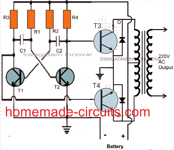
A transistor multivibrator circuit basically is composed of two symmetrical half stages, here its formed by the left and the right hand side transistor stages which conduct in tandem or in simple words the left and the right stages conduct alternately in a kind of a perpetual “motion”, generating a continuous flip flop action.
The above action is responsible of creating the required oscillations for our inverter circuit. The frequency of the oscillation is directly proportional to the values of the capacitors or/and the resistors at the base of each transistor.
Lowering the values of the capacitors increases the frequency while increasing the values of the resistors decreases the frequency and vice versa. Here the values are chosen so as to produce a stable frequency of 50 Hz.
Readers, who wish to alter the frequency to 60 Hz, may easily do it by just changing the capacitor values appropriately.
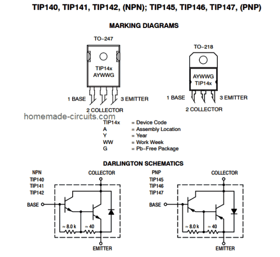
Transistors T3 and T4 are placed at the two output arms of the AMV circuit. These are high gain; high current Darlington paired transistors, used as the output devices for the present configuration.
The frequency from the AMV is fed to the base of T3 and T4 alternately which in turn switch the transformer secondary winding, dumping the entire battery power in the transformer winding.
This results in a fast magnetic induction switching across the transformer windings, resulting the required the mains voltage at the output of the transformer.
Parts Required
You will require the following components for making this 50 watt homemade inverter circuit:
| Component | Value |
|---|---|
| R1, R2 | 100K |
| R3, R4 | 330 Ohms |
| R5, R6 | 470 Ohms, 2 Watt |
| R7, R8 | 22 Ohms, 5 Watt |
| C1, C2 | 0.22 uF, Ceramic Disc |
| D1, D2 | 1N5402 or 1N5408 |
| T1, T2 | 8050 |
| T3, T4 | TIP142 |
General purpose PCB = cut into the desired size, approximately 5 by 4 inches should suffice.
Battery: 12 volts, Current not less than 10 AH.
Transformer = 9 – 0 – 9 volts, 5 Amps, Output winding may be 220 V or 120 volts as per your country specifications
Sundries: Metallic box, fuse holder, connecting cords, sockets etc
Testing and Setting Up the Circuit
After you finish making the above explained simple inverter circuit, you may do the testing of the unit in the following manner:
Initially do not connect the transformer or battery to the circuit.
Using a small DC power supply power the circuit.
If everything is done rightly, the circuit should start oscillating at the rated frequency of 50 Hz.
You can check this by connecting the prods of a frequency meter across T3’s or T4’s collector and the ground. The positive of the prod should go to the collector of the transistor.
If you don’t own a frequency meter, never mind, you do a rough checking by connecting a headphone pin across the above explained terminals of the circuit. If you hear a loud humming sound, will prove that your circuit is generating the required frequency output.
Now it’s time to integrate the battery and the transformer to the above circuit.
Connect everything as shown in the figure.
Connect a 40 watt incandescent lamp at the output of the transformer. And switch ON the battery to the circuit.
The bulb will immediately come ON brightly…..your homemade 50 watt inverter is ready and may be used as desired by for powering many small appliances whenever required.
Design#2: 50 Watt Mosfet Inverter Circuit
The circuit explained above involved power transistors now let's see how the same concept may be utilized with mosfets making the configuration much easier and straightforward, yet more robust and powerful.
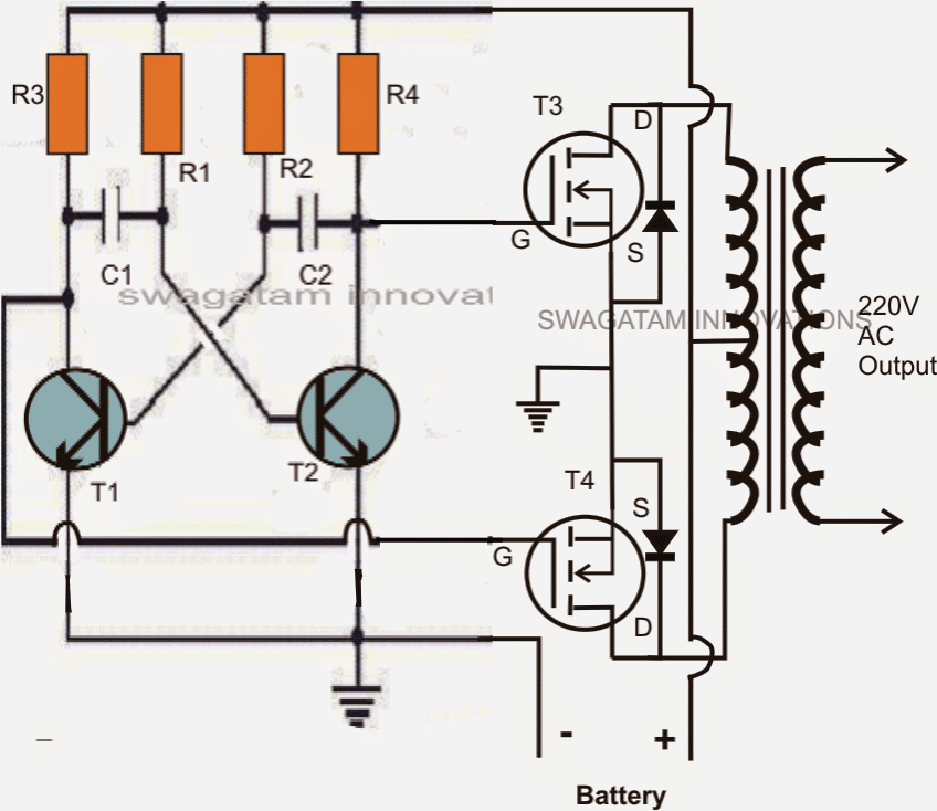
Rest of the stages are pretty much the same, in the earlier circuit we saw the involvement of a transistor based astable multivibrator for the generation of the required 50 Hz oscillations, here too we have incorporated a transitor operated AMV.
The earlier circuit had a couple of 2N3055 transistors at the output and as we all know driving power transistors efficiently requires proportionate amount of base drive, relative to the load current, because transistors depend on current drive rather than voltage drive, in contrast to mosfets.
Meaning, as the proposed load becomes higher, the base resistance of the relevant output transistor also gets dimensioned accordingly for enabling optimal amount of current to the base of the transistors,
Due to this obligation, in the previous design a additional driver stage had to be incorporated for facilitating better drive current to the 2N3055 transistors.
However when it comes to mosfets, this necessity becomes completely insignificant.
As can be seen in the given diagram, the AMV stage is instantly preceded by the relevant gates of the mosfets, because mosfets have very high input resistance, which means the AMV transistors wouldn't be unnecessarily loaded and therefore the frequency from the AMVwouldn't be distorted due to the integration of the power devices.
The mosfets are alternately switched, which in turn switches the battery voltage/current inside the secondary winding of the transformer.
The output of the transformer gets saturated delivering the expected 220V to the connected loads.
Parts List
| Component | Value |
|---|---|
| R1, R2 | 27K |
| R3, R4 | 220 Ohms |
| C1, C2 | 0.47uF/100V, metallized |
| T1, T2 | BC547 |
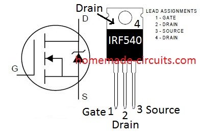
| T3, T4 | Any 30V, 10A N-channel MOSFET or a couple of IRF540 |
| Diodes | 1N5402 or any 3A rectifier diode |
Transformer = 9-0-9V, 8 amp
Battery = 12V,10AH
Video showing the Testing process of the 50 watt inverter circuit:



Questions & Answers
Sir,
Actually this is the time to Upgrade this particular circuit with above mention features to make it NEW and secondly, searching for this features individually on the blog is wastage of time, if found, the connections should be logically correct and this is very time consuming…what do you say ???
Regards,
You can added more number of mosfets by directly connecting their gates, drains and sources parallel with the existing mosfets, just make sure that each mosfet has it's own separate resistors similar to R5/R6, drains and sources can be directly joined in parallel…the resistor ends can be joined with transistor collectors as done with the existing mosfets.
All mosfet numbers should be exactly identical
yes you can do it.
you can try any closely rated trafo…
Hello Sadi,
Just type "smart automatic charger" in the above search box, you will find your circuit there.
Hi Sadi,
You can use 12-0-12V trafo, but you will need a fully charged battery upto 14V for acquiring the required 230V output from it.
use a 12V/5amp transformer and a 12V 10AH battery for getting higher current outputs
That's cool Sadi,
Yes it will work, please refer to this post:
https://www.homemade-circuits.com/2013/04/how-to-modify-square-wave-inverter-into.html
Hello Sadi,
I think the mosfets might have got damaged due to the absence of flyback diodes across D and S of the mosfets, I'll update the diagram, please add it in your circuit accordingly.
Yes Sadi, I know that but since I am not able to figure out any other potential issue in the design,so I am assuming it to be the possible cause of your mosfet damage.
Also connect 1K resistors across collector/emitter of T1/T2, that might help control transients.
Hello Sadi,
That's great news.
For resistive loads such as bulbs, the frequency isn't important, even for CFLs this won't be a problem.
If your PCB layout is correct as per the diagram then it would definitely work
Helo Sadi,
I am not able to identify any potential threat that might be causing damage to the mosfets, however during transition periods there may be a chance of the mosfets conducting simultaneously for a split second, although quite unlikely it's better to tackle it also.
put zener diodes in series with the emitters of the BC547 transistors, anode to ground and cathode to emitter. zener value can be anything between 3 and 9v.
Don't worry about the transistor biasing voltage because here it would be continuously changing from positive to negative vice versa due to the oscillating nature of the circuit…..assuming that you have built the AMV correctly.
Hello Sadi,
Yes heatsink is necessary if the devices are getting hot, use a size which keeps the mosfets reasonably cool.
i desing the ckt but its not working….. wht i do sir…….????
hi sir
this srinivas
ihave a doubt can i use irf3205 mosfet with circuit and ihave a 600 va computer ups transformer is 12-0-12
please suggest me
thank & regards
Hi Srinivas,
Yes you can use the mosfet with the mentioned transformer.
thanks for the answer!!!
what modifications will I make to obtain 200 watt ?
500 watts ?
sine wave?
the above circuit will give 200watt easily, for sine wave again you will have to employ a 555 IC and diode network at the gates of the mosfets.
hi swagatam,
Well i stated you that i am making an inverter.
my actual goal of making an inverter, which can actually able to power big devices like tv or computer of 300 watts from low power consuming devices like 12 volt adapters. i know is bit of impossible idea?
but i thought that first we need to connect an 14 volt strictly regulated current and voltage adapter to the mains. And we will connect the output to the battery of 12 volt for charging and after charging we will take up an 800VA inverter and connect it to the battery, leaving the mains adapter switched on as it is. Simultaneously we will switch the inverter on and give out the load. it will usually draws current from adapter only. but if the load increases, the battery act as an supplier. as i stated that battery should be charged first and then should be connected to the inverter. and this is something adding a wire in between the mains and the load. can you tell me if there is any possibility of this design?
I read an common inverter design, there is always a backup like system where mains are either connected directly to the load or they are backed up by an battery if there is mains failure.
can we also replace battery with ultra or super caps following my design?
please please reply.
advance thankx
Hi Shadab,
What you are assuming is incorrect and therefore will not work, 300 watts means 300/12 = 25amps, you will need an adapter capable of providing 25amps for relieving the battery from the load…..
hi sir. Shall i use npn transistor (2n3904) in oscillation stage with reverse polarity.
you can use it in the correct polarity, matching with the shown BC547 poarity
Hi! This is samar i want to ask you about this circuit that can i use mylar or electrolyrtic capacitor instead of metallized and the second thing is that can i take 30 watts load from 12-0-12, 3amp transformer rating. thanks in advance. waiting for your kind reply.
Hi, yes mylar or electrolytic caps can be used, if the trafo is truly rated at 3 amps then 30 amps can be expected from it.
Hello! i want to ask you about a inverter circuit i made an inverter
circuit by follow this circuit diagram but when i connected 12-0-12, 1
ampere transformer it cant converting to 220volt and transformer is
heated can plz tell me about the problem and i got 12,12 volt from
mosfet transitor can you plz explain?
hello if your transformer is getting hot, it means either the transformer is faulty or the inverter is not oscillating.
First make sure the junction of R4/R5 is generating the required 50 Hz frequency, confirm this by keeping the transformer disconnected…
if this is OK, it would indicate a possible fault in the transformer
hi sir i am a new comer here i want to know that r1 r2 has 27 kohm values each?
also for r3 r4 r5 r6?
ur respnse will be highly appreciated.
thank you
Hi Prateek, it's given in the parts list below the diagram, yes R1/R2 = 27K ohms
rest are 470 ohms
Hello,
Is it requred to use 12-0-12v transformer or it could be with only two wires?
And also why is used 3 wires primar?
Thank you in advance.
BR
Hi, yes a center tap trafo is necessary here since the circuit uses a push pull type of topology, two wire trafo will not work here.
the primary center tap is used to connect with the battery
for a 12V batt the trafo primary must be rated at 9-0-9V, that is, slightly lower than the battery voltage
Hi sir, I want to ask you a question regarding the IC CD4047. My question is that, what number of mosfets can the IC Cd4047 drive? i.e. What is the maximum output power(WATTS) I can get if I use Cd4047 inverter circuit? Waiting for your reply sir.
Hi Purna, you can use any desired number of mosfets with this IC or any similar IC and get any desired power output from the inverter transformer.
the transformer and the battery decide the power (wattage), not the IC, the IC is only for the initiating the mosfets as per the set frequency.
Thanks for the help sir. Can you please suggest an IC number as I want to build a circuit that can drive loads upto 1000watt. I am going to use IRF 3205 mosfets.
4047 IC is the ideal IC to start with, other ICs are relatively complex to configure
Thank you very much for your help sir.
Plz send me
Pure sinewave inverter design for grid synchronization for home inverter with 500watt
hello sir.i have a problem with an inverter and would love u to help me out. i built a square wave inverter with ic cd4047 i use irf3205 fets at d output.i used four irf3205 two on each side.couldnt get a 12v-0-12v transformer so i used a 16v-0-16v transformer rated around 4amp i power d inverter with a 12v 75ah car battery.my problem now is am geting above 250v ac and anytime i connect a 60-100watt filament bulb it may not glow or when it glows it dim and the voltage drops to around 100v ac.pls help tanks
Hello Mayokun,
first of all the transformer voltage should be always lower than the battery voltage…for a 12V, it could be around 9-0-9V, secondly a 4 amp trafo as in your case will be able to produce:
4 x 12 = 36 watt in most ideal conditions…so expecting a 100 watt is no good
use a 9-0-9 or a 12-0-12V trafo rated at at least 10 to 15 amps for illuminating a 100 watt brightly
thanks alot for the reply.one more question,why is it that such transformer of the same wattage that i use powers the cpu and monitor in a ups and usaid mine even cnt power a 100watt bulb. secondly pls can u post the modified sine wave of the above circut.thanks again
CPUs and monitors are designed to work with low voltages also, since these have SMPS which are assigned to work even at as low as 100V.
the modified design can be seen here:
https://www.homemade-circuits.com/2013/04/how-to-modify-square-wave-inverter-into.html
thanks for the help.really greatful.sori another question to go.pls if i want to upgrade to aroun 350watt of the aboove circuit what are the modifications to make.thanks again
just upgrade the trafo, that's all
thank you alot greatful
Thank you so much sir
sir
am Arun.
could you plz show me an image of 0.47uF/100V metallized capacitor?
I went to retailer and asked for 474J 100V capacitor,but he did'nt heard understand for what am asking for!
hope you may help me
arun, you can use any standard ceramic 0.47uF capacitor, the given specification is not critical.
you can use other values also for C1/C2 such as 0.1uF which is five times less than 047uF, but that would mean you will need to increase the 27k values five times more, that's equal to around 140K
Sir
What should I do with the Earth indicated points on the above circuit???
the earth is just the battery negative, nothing more.